
K-WANG
+086-15305925923
Service expert in industrial control field!


Product
Article
NameDescriptionContent
Adequate Inventory, Timely Service
pursuit of excellence


Ship control system
Equipment control system
Power monitoring system
Current position:
新闻动态
newS
Brand
ABB Bailey* network90 Loop Interface/Bus Interface(LIM/BIM)
ABB Bailey* network90 Loop Interface/Bus Interface(LIM/BIM)
ABB Bailey* network90 Loop Interface/Bus Interface(LIM/BIM)
WARNING notices as used in this manual apply to hazards or unsafe practices which could result in severe personal injury
CAUTION notices apply to hazards or unsafe practices which could result in minor personal injury or property damage.
or death.
NOTES highlight procedures and contain information which assists the operator in understanding the information con.
tained in this manual.
WARNING
INSTRUCTION MANUALS
DO NOT INSTALL, MAINTAIN OR OPERATE THIS EQUIPMENT WITHOUT READING, UNDERSTANDING AND FOLLOW.
ING THE PROPER Babcock & Wilcox, Bailey Controls INSTRUCTIONS AND MANUALS, OTHERWISE INJURY OR
DAMAGE MAY RESULT.
RADIO FREQUENCY INTERFERENCE
BE EXERCISED WITH REGARD TO THE USE OF PORTABLE COMMUNICATIONS EQUIPMENT IN'THE AREA AROUND
MOST ELECTRONIC EQUIPMENT IS INFLUENCED BY RADIO FREQUENCY INTERFERENCE (RFI). CAUTION SHOULD
EQUIPMENT CAUTIONING AGAINST THE USE OF PORTABLE COMMUNICATIONS EQUIPMENT.
SUCH EQUIPMENT. PRUDENT PRACTICE DICTATES THAT SIGNS SHOULD BE POSTED IN THE VICINITY OF THE
POSSIBLE PROCESS UPSETS
MAY UPSET THE PROCESS BEING CONTROLLED. SOME PROCESS UPSETS MAY CAUSE INJURY OR DAMAGE.
MENT CONTROLLED BY THIS PRODUCT.ADJUSTING OR REMOVING THIS PRODUCT WHILE IT IS IN THE SYSTEM
MAINTENANCE MUST BE PERFORMED ONLY BY QUALIFIED PERSONNEL AND ONLY AFTER SECURING EQUIP.
AVERTISSEMENT
MANUELS D'OPERATION
NE PAS METTRE EN PLACE, REPARER OU FAIRE FONTIONNER CE MATERIEL SANS AVIOR LU, COMPRIS ET SUIVI
LES INSTRUCTIONS REGLIMENTAIRES DE Babcock & Wilcox, Bailey Controls TOUTE NEGLIGENCE A CET EGARD
PURRAIT ETRE UNE CAUSE D'ACCIDENT OU DE DEFAILLANCE DU MATERIEL
PERTURBATIONS DE LA FREQUENCE RADIOPHONIQUE
LA PLUPART DES EQUIPEMENTS ELECTRONIQUES SONT SINSIBLES AUX PERTURBATIONS DE LA FREQUENCE
PORTATIF, LA PRUDENCE EXIGE QUE LES PRECAUTIONS A PREDRE DANS CE CAS SOIENT SIGNALEES AUX
RADIO. DES PRECAUTIONS DEVRONT ETRE PRISES LORS DE L'UTILISATION DE MATERIEL DE COMMUNICATION
ENDROITS VOULOUS DANS VOTRE USINE.
PERTES PROCEDE RENVERSEMENTS
L'ENTRETIEN DOIT ETRE ASSURE PAR UN PERSONNEL QUALIFIE ET EN CONSIDERATION DE L'ASPECT
SECURITAIRE DES EQUIPEMENTS CONTROLES PAR CE PRODUIT. L'ADJUSTEMENT ET/OU L'EXTRACTION DE CE
PRODUIT LORSQUI'IL EST INSERE A UN SYSTEME ACTIF PEUT OCCASIOINNER DES A-COUPS AU PROCEDE CON-
BLESSURES,
TROLE. SUR CERTAINS PROCEDES, CES A-COUPS PEUVENT EGALEMENT OCCASIONNER DES DOMMAGES OU
NOTICE
The information contained in this document is subject to change without notice.
Bailey Controls Company, its affiliates, employees, and agents, and the authors of and contributors to this publica-
and fitness for a particular purpose), for the accuracy, currency, completeness, andior reliability of the information
tion specifically disclaim all liabilities and warranties, express and implied (including warranties of merchantability
ment selected in whole or part with the user of/or in reliance upon information contained herein. Selection of materials
contained herein and/or for the fitness for any particular use and/or for the performance of any material and/or equip-
and/or equipment is at the sole risk of the user of this publication.
This document contains proprietary information which is protected by copyright. All rights are reserved. No part of
this document may be photocopied or reproduced without the prior written consent of Bailey Controls Company.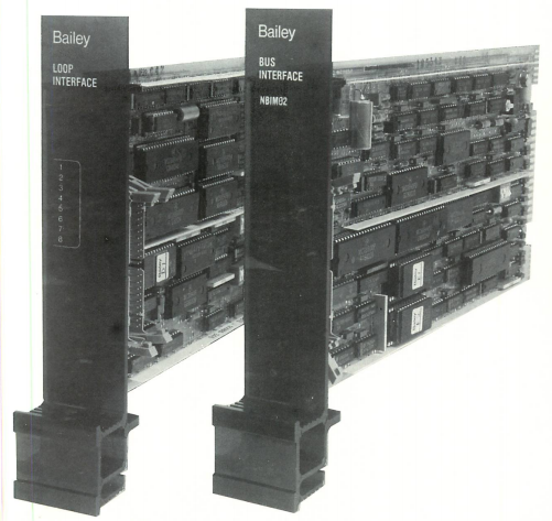
General
Installation - gives step-by.step procedures for
preparing the LIM/BIM'pair for installation in
The Loop and Bus Interface Modules(LIM/BIM) pro-
the PCU.
vide the principal communication interface between
NETWORK 90 Process Control Units and the Plant
Operation - provides the user with normal,
Communication Loop (PCL). Information is passed
everyday operating instructions.
over the Loop to other nodes. A node can be a Pro-
cess Control Unit (PCU),Management Command
Troubleshooting - explains possible error
System (MCS), Operator Interface Unit (OIU),Plant
situations and correctivemeasures; also
Loop Gateway(PPG) or Computer Interface Unit (CIU).
includes service/replacement information.
A maximum of 63 nodes, in any combination, can be
on the Loop.
How to Use this Manual
The basic function of the BIM is to gather data
from modules and transfer it to the LIM. The basic
Read the introductory material first. Then, proceed to
function of the LIM is to examine the data and
the Theory of Operation section to get a fundamen-
transmit it to the assigned destination on the Loop.
tal understanding of how the modules work. Next,
Detailed theory of LIM/BIM operation is covered in the
read the Installation section. This should be read
Theory of Operation section of this document.
thoroughly, and all preparatory steps performed,
before putting the modules into operation. After
This document is divided into the following
installing the modules, read the Operation section to
sections:
find out what to look for in the normal and abnormal
operating modes. Refer to the Troubleshooting sec.
tion if any abnormal situations occur after putting the
Theory of Operation - provides an in-depth view
modules into operation.
of how the LIM/BIM pair work.
Glossary
Common Database
Data shared by LIM/BIM pairs on the Plant Loop.
Exception Report
Information update generated when a point change is greater than a speci-
fied significant amount.
Frame
Valid string of bytes on the Plant Loop.
Node
Any drop on the Loop; can be a Management Command System, Operator
Interface Unit, Computer Interface Unit, Plant Loop Gateway or Process
Control Unit.
Packing
The process of grouping multiple Exception Reports into one message.
Plant Communication Loop
The unidirectional highway for serial data shared by all nodes on the Loop.
Polling Rate
The time interval that the BIM checks the modules for Exception Reports.
Receive Data
Data received by destination PCU.
Synchronization Time
The time it takes for internal circuitry to readjust when a module goes into or
comes out of bypass.
Transmit Data
Data sent by one PCU to another.
- YOKOGAWA
- Reliance
- ADVANCED
- SEW
- ProSoft
- WATLOW
- Kongsberg
- FANUC
- VSD
- DCS
- PLC
- man-machine
- Covid-19
- Energy and Gender
- Energy Access
- Renewable Integration
- Energy Subsidies
- Energy and Water
- Net zero emission
- Energy Security
- Critical Minerals
- A-B
- petroleum
- Mine scale
- Sewage treatment
- cement
- architecture
- Industrial information
- New energy
- Automobile market
- electricity
- Construction site
- HIMA
- ABB
- Rockwell
- Schneider Modicon
- Siemens
- xYCOM
- Yaskawa
- Woodward
- BOSCH Rexroth
- MOOG
- General Electric
- American NI
- Rolls-Royce
- CTI
- Honeywell
- EMERSON
- MAN
- GE
- TRICONEX
- Control Wave
- ALSTOM
- AMAT
- STUDER
- KONGSBERG
- MOTOROLA
- DANAHER MOTION
- Bentley
- Galil
- EATON
- MOLEX
- Triconex
- DEIF
- B&W
- ZYGO
- Aerotech
- DANFOSS
- KOLLMORGEN
- Beijer
- Endress+Hauser
- schneider
- Foxboro
- KB
- REXROTH
- YAMAHA
- Johnson
- Westinghouse
- WAGO
- TOSHIBA
- TEKTRONIX
- BENDER
- BMCM
- SMC
- HITACHI
- HIRSCHMANN
- XP POWER
- Baldor
- Meggitt
- SHINKAWA
- Other Brands
- UniOP
- KUKA
- IBA
- Beckhoff
- ADLINK
51
-
Beckhoff CX5020-0112 - PLC Module
-
Beckhoff CP2912-0000 - Control Panel
-
Beckhoff C6920-1047-0030 - industrial control cabinet control PC
-
BECKHOFF CX1020-0121 - CPU Module Power Supply Setup
-
Beckhoff EL6752 - DeviceNet Master EtherCAT Terminal
-
Beckhoff IP1002-B518 - Fieldbus Box Module
-
Beckhoff CP6606-0001-0020 - 7 inch Economy Panel PC incl. Connection Cable
-
Beckhoff CX5010-0111 - Controller Module
-
BECKHOFF AX2020-S62000-520 - SERVO DRIVE 5.76
-
Beckhoff EL1904 - 4-Channel Digital Input Module
-
Beckhoff EP9224-0037 - 4-Channel Power Distribution Box EtherCAT
-
Beckhoff CX2900-0026 - Solid State Flash Memory Card 20GB CFast
-
Beckhoff BK7500 - SERCOS Interface Fieldbus Bus Coupler Terminal
-
Beckhoff Ep2328-0002 - 4-Channel Input 4-Channel Output EtherCAT Box IP67
-
Beckhoff CX1020-0111 - Controller Kit Combo Interface Modules
-
B&R X20AI2237 - X20 System Analog Input Interface Module
-
Beckhoff CP2221-0010 - Multi-Touch Built-In Panel PC Touchscreen
-
Beckhoff CX1500-M310 - Fieldbus Master Interface Module 24V
-
Beckhoff CX2100-0904 - Power Charging Module Smart UPS Extension
-
Beckhoff CP3918-0000 - Multi-Touch Control Panel 18.5-Inch Monitor
-
Beckhoff CP2915-0000 - 15-Inch Multi-Touch Built-In Control Panel
-
Beckhoff CP7037-1027 - HMI Industrial Control Panel Built-In PC
-
Beckhoff EL3152 - 2-Channel Analog Input Terminal 4-20mA EtherCAT
-
Beckhoff CP6607-0000-0020 - 5.7-Inch Built-In Panel PC HMI Touch
-
Beckhoff EJ1809-0000 - 16-Channel Digital Input Pluggable Signal Level Terminal
-
Beckhoff AM8563-0N10-0000 - Synchronous Servo Motor
-
Beckhoff AX2006-S60600-520 - Compact Servo Drive Inverter
-
Beckhoff AM8053-0K20-0000 - Servo Motor with Planetary Gearbox AG3210
-
Beckhoff AM8042-0FH1-0000 - Synchronous Servo Motor
-
Rexroth R911338600 - IndraControl V HMI Terminal Beckhoff PCI Card FC9002
-
Beckhoff AX5125-0000 - 3 Phase Industrial Servo Drive 1000Hz
-
Beckhoff EP2328-0002 - 4-Channel Digital Input 4-Channel Output EtherCAT Box
-
B&R 7CP476-02 - System 2005 RTD CPU Module 3IF681.86 Interface
-
Beckhoff AX8620-0000-0000 - Power Supply Module Axis Drive System
-
Beckhoff CX1010-0111 - PLC Module CPU Controller 24V
-
Beckhoff AM8043-0H10-0000 - Synchronous Servo Motor
-
Beckhoff C6240-1009 - Control Cabinet Industrial PC Mainframe
-
Beckhoff BX8000-0000 - Bus Terminal Controller HW 4.4 Standalone
-
Beckhoff CP7721-1089-0020 - 12.1-Inch Touch Screen HMI Panel PC
-
Beckhoff CP7132-0001 - Industrial Built-In Panel PC Screen
-
Beckhoff CP2912-0010 - Multi-Touch Built-In Control Panel Display
-
Beckhoff CP2915-0000 - 15-Inch Multi-Touch Built-In Control Panel
-
Beckhoff AM8532-1EN0-0000 - Synchronous Servo Motor
-
Beckhoff AX5203-0000 - 2-Channel Digital Compact Servo Drive
-
Beckhoff CX2020-0141 - Embedded PC Core CPU Module
-
Beckhoff CP6832-0002-0010 - Built-In Industrial Control Panel Display
-
Beckhoff CX5020-0112 - Embedded PC CPU Control Module
-
Beckhoff CX5140-0175 - 4GB Embedded PC CPU Unit 24V
-
Beckhoff EL3681-0030 - Digital Multimeter Calibration Terminal EtherCAT
-
Beckhoff CP7201-1000-0000 - Industrial PC Touch Screen HMI Monitor
-
Beckhoff CP7232-1001-0000 - Industrial Panel PC Touch Screen
-
Beckhoff C6930-1032-0040 - Control Cabinet Industrial PC System
-
Beckhoff AX5125-0000 - 3 Phase Industrial Servo Drive 1000Hz
-
Beckhoff CP3916-1424-0000 - Multi-Touch Built-In Control Panel
-
B&R 1900071142 - Lemoine Fieldbus Communication Interface Module
-
Beckhoff EL2872 - 16-Channel Ribbon Cable Digital Output Terminal
-
Beckhoff CX2030-0120 - Embedded PC CPU Base Module Controller
-
Beckhoff CP3919-0000 - 19-Inch Multi-Touch Control Panel Touchscreen
-
Beckhoff AX5101-0000-0202 - Servo Driver Compact Intelligent Drive 180V
-
Beckhoff CX5130-0135 - Embedded PC Controller Module
-
Beckhoff CP3719-1061-0010 - Multi-Touch Panel PC Outer Housing Enclosure
-
Beckhoff CP3919-1033-0000 - 19-Inch Touch Industrial Panel Keyboard
-
Beckhoff CX5020-0111 - Embedded PC PLC CPU Module
-
Beckhoff FC5102-0000 - 2-Channel CANopen PCI Control Board Card
-
Beckhoff CX9001-1101 - Embedded PC CPU Network I/O System Module
-
Beckhoff CX1100-0920 - Smart Position Sensor Interface Module
-
B&R 4P3040.01-490 - Operator Panel PLC Interface Communication Module
-
Beckhoff CP2612-0000 - Dual-Touch Built-In Panel PC HMI
-
Beckhoff CP7002-1043-0010 - Touchscreen Display HMI Panel Terminal
-
Beckhoff CX9020-0115 - Embedded PC Controller Module
-
Beckhoff CX5140-0155 - 4GB Embedded PC CPU Module Die Industry
-
B&R 7DI435.7 - System 2005 Universal Digital Input Output Module
-
Bihl+Wiedemann BWU1568 - AS-i Master to Profibus Gateway Module
-
Beckhoff C6920-0070 - Control Cabinet Industrial PC 8GB Win 10
-
B&R X20AI2322 - 2-Channel Temperature Analog Input Module
-
Beckhoff CP2912-0000 - 12-Inch Touchscreen Display Monitor Screen
-
Beckhoff CP6022-1001-0010 - 15-Inch Built-In Control Panel
-
Beckhoff AM8031-0D10-0000 - Synchronous Servo Motor
-
Beckhoff CX5010-0111 - Embedded PC Controller CPU Module
-
Beckhoff CP7232-1000-0000 - Industrial Panel PC Touch Display Screen
-
Beckhoff CP7802-0011-0000 - 15-Inch Industrial Touchscreen Control Panel
-
Beckhoff C6320 - Control Cabinet Industrial PC
-
Beckhoff CX1030-0012 - Basic CPU Module Windows CE 6.0
-
Beckhoff CP2919-0000 - Installation Multi-Touch Control Panel
-
Beckhoff CX1020-0000 - Controller Set Stack System Pack
-
B&R 3DO480.6 - System 2005 Digital Output Module
-
Beckhoff EL3101 - 1-Channel Analog Input Terminal Differential +/-10V
-
Beckhoff AX8108-0200-0000 - Axis Feed Module Servo Drive
-
Beckhoff CP7802-1241-0010 - 15-Inch Industrial Touchscreen Control Panel
-
Beckhoff FC2002-0000 - 2-Channel Lightbus Data Acquisition PCI Card
-
Beckhoff CX5120-0155 - 2GB Embedded PC Intel Atom Controller
-
Beckhoff Cx9020-0111 - 1GB Basic CPU Module Embedded PC
-
Beckhoff CP6901-0001-0000 - 12-Inch Economy Built-In Control Panel
-
Beckhoff CX9020-0111 - Embedded PC CPU Basic Module
-
Beckhoff CX5130-0100 - 4GB Embedded PC CPU Module
-
Beckhoff CP2715-0010 - Multi-Touch Built-In Panel PC
-
Beckhoff CX2033-0175 - Embedded PC CPU Module Core i7
-
Beckhoff CP7201-1000-0000 - 12-Inch Touchscreen Panel PC AMAT Green Box
-
Beckhoff EL4038 - 8-Channel Analog Output Terminal 0-10V EtherCAT
-
Beckhoff CP6802-0000-0000 - Built-In Control Panel HMI Screen
-
Beckhoff AM8042-0F21-0000 - Synchronous Servo Motor
-
Beckhoff CX5120-0141 - Embedded PC Basic Controller Module
-
Beckhoff C6930-0050 - Control Cabinet Industrial PC System
-
Beckhoff CP6831-0002-0000 - Built-In Industrial Control Panel
-
Beckhoff CP6919-0001-0000 - Built-In Control Panel Display Unit
-
Beckhoff CP7201-1019-0030 - Built-In Panel PC HMI Monitor Screen
-
Beckhoff CP6809-0001-0000 - 6.5-Inch Touch Panel ELO Accutouch HMI
-
Beckhoff CX1020-0000 - Control Kit Combo Stack Units
-
Beckhoff cp3918-1012-0000 - 18.5-Inch Multi-Touch Control Panel
-
Beckhoff CX5140-0123 - 4GB Embedded PC CPU Module
-
Beckhoff C3230TP - Industrial PC Rackmount Workstation
-
Beckhoff CP6801-1006-0010 - Touch Panel HMI Display Unit
-
Beckhoff CX8010 - Embedded PC Controller Module
-
Beckhoff CP7011-0001 - Control Panel CRT Operator Pendant Monitor HMI
-
Beckhoff CX1010-0111 - Embedded PC CPU PLC Module 24V
-
Beckhoff CP2915-0000 - 15-Inch Multi-Touch Built-In Control Panel
-
Beckhoff CP7802 - Industrial Touch Screen Control Panel Monitor
-
Siemens 6AV7452-1AB00-0FB0 - Industrial PC Panel 877 Beckhoff PCI Cards
-
Beckhoff CP2612-0000 - Dual-Touch Integrated Panel Monitor Screen
-
Beckhoff CX5140-0175 - Embedded PC Core Controller
-
Beckhoff Cp6202-0001-0010 - Economy Built-In Panel PC System
-
Beckhoff C6320-0010 - Control Cabinet Industrial PC Unit
-
Beckhoff CP2919-0000 - Multi-Touch Built-In Control Panel Screen
-
Beckhoff CX9020-0111 - Embedded PC CPU Controller Module
-
B&R 3BP151.41 - System 2005 Backplane Base Module
-
Siemens 6AV7452-1AB00-0FB0 - Panel PC 877 with Beckhoff Communication Cards FC3101 FC7501
-
Beckhoff CX9001-1101 - Embedded PC System Fieldbus Module Bundle
-
Beckhoff CX1001-0122 - CPU Module PLC Controller 128MB RAM

K-JIANG

Add: Jimei North Road, Jimei District, Xiamen, Fujian, China
Tell:+86-15305925923