
K-WANG
+086-15305925923
Service expert in industrial control field!


Product
Article
NameDescriptionContent
Adequate Inventory, Timely Service
pursuit of excellence


Ship control system
Equipment control system
Power monitoring system
Current position:
新闻动态
newS
Brand
ABB Data Sheet ControlIT Harmony Analog I/O
ABB Data Sheet ControlIT Harmony Analog I/O
ABB Data Sheet ControlIT Harmony Analog I/O
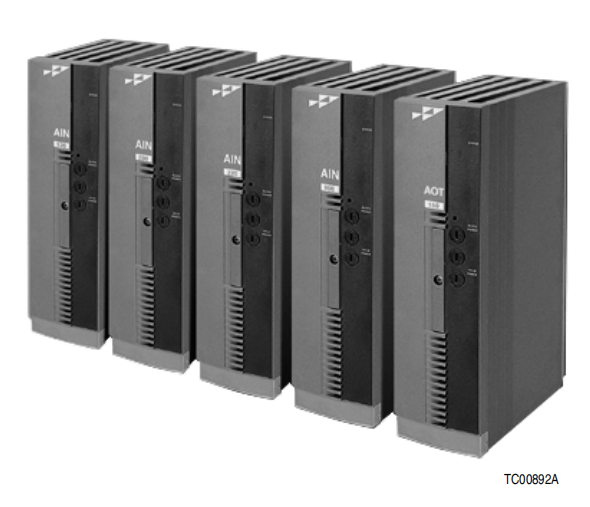
The Harmony Input/Output (I/O) System utilizes a variety of input and output blocks to inter face process signals to the Symphony ™Enterprise Management and Control System. Analog
input (AIN) blocks interface field inputs such as pressure and flow transmitter signals, thermo couple (TC) inputs, and resistive temperature device (RTD) inputs. Analog output (AOT) blocks
provide output signals to adjust final control elements such as control valves, pumps, positioners,
actuators, etc. These analog blocks along with other types of blocks for digital and control I/O
interface and remote I/O communication combine to create a complete I/O system (Fig. 1). Refer
to the Harmony Input/Output System overview for a complete system description.
Operation
Each analog I/O block has an onboard microprocessor which controls and performs the following
functions for the block:
■ Hnet communication.
■ Analog input/output processing.
■ Redundancy link communication.
■ Block diagnostics.
■ Status reporting.
Along with these functions, the microprocessor is also responsible for executing the I/O block
portion of the control configuration. The complete control configuration made up of linked func tion codes resides and is retained in the Harmony controller at all times. The controller only off
loads a portion of the configuration to be executed by the individual I/O blocks.
Function codes are predefined, fixed function algorithms. When interfacing analog I/O blocks, the
controller utilizes the following function codes:
■ I/O device definition (FC 221).
■ Analog input/channel (FC 222).
■ Analog output/channel (FC 223).
Specifications are set on a per channel basis rather than on an I/O group basis. The function codes
provide addressing, and start-up, execute (i.e., run time), override, simulation, and failure mode
operation specifications. The I/O channel function codes are exception reporting function codes.
Analog Input
The Harmony I/O System supports four to 20 milliampere, high level –10 to +10 VDC, low level
-100 to +100 millivolt (DC), thermocouple (TC), and resistive temperature device (RTD) inputs
through AIN blocks:
■ AIN-120 - High level voltage, current in.
■ AIN-200 - Isolated TC, high level voltage, low level voltage in.
AIN-220 - Isolated TC, high level voltage, low level voltage, current in.
■ AIN-300 - Isolated RTD in.
Data Conversion
An AIN block reads currents or voltages at its input channels, scales and converts the inputs to
real values in engineering units, then reports the input values to the controller. The block provides
channel status information along with each reported input.
High and low level inputs are converted to the proper engineering units based on input type and
engineering unit high and low value specifications. Thermocouple and RTD inputs are converted
to the proper engineering units (degrees C or degrees F) using predefined conversion tables for
each type of thermocouple and RTD supported.
The AIN-120 block uses a single successive approximation analog-to-digital converter through
which all channels are multiplexed. This type of A/D conversion method is fast (ten microseconds
per conversion), which allows multiple channels to be sequentially multiplexed through one converter. Redundancy provides a backup analog-to-digital conversion.
The AIN-200, AIN-220, and AIN-300 blocks have dedicated Delta-Sigma analog-to-digital converters on each channel. These converters are slower (50 milliseconds per conversion); however,
no multiplexing is required since each channel performs independent conversions. The converters
also have built-in digital signal processing which provides low pass filtering. The AIN-200,
AIN-220, and AIN-300 blocks have optically isolated input channels.
Digital Signal Processing
The AIN-120 block uses a floating point digital signal processor (DSP) to achieve low pass filtering. The advantage to using a DSP device for this function is that significant noise rejection can be
achieved (better than 70 dB) while maintaining fast settling time to an input step response (75 milliseconds). As stated previously, the Delta-Sigma analog-to-digital converters used in the AIN-200,
AIN-220, and AIN-300 blocks have built-in digital signal processing which provides low pass
filtering.
Calibrations
No field calibrations are required. The electronics automatically perform the following adjustments to the raw analog inputs depending on input type:
■ Drift correction using onboard zero and span reference voltages.
■ Lead wire resistance adjustment for low level, thermocouple, and RTD inputs.
■ Cold junction temperature compensation for thermocouple inputs using either an internal or
external cold junction reference.
Current Limiting
The analog input channels provide onboard current limiting for short circuit protection. The current limiting prevents circuit damage that can result from excessive current levels at an input
channel caused by field input faults. Specifically, the four to 20 milliampere input channels are
protected against shorts across the transmitter, across positive and negative terminals, from the
positive terminal to ground, and from the negative terminal to ground. A channel will recover to
full function after correcting the fault condition.
The Harmony I/O System supports four to 20 milliampere outputs through an AOT-150 block.
This block receives output demand values in engineering units from the controller, scales the
demand values to percentages of output, and converts them to analog voltages or currents at the
output channels. User selectable default states of zero percent, 100 percent, or hold output are
provided.
Calibrations
The electronics automatically adjust analog outputs to compensate for supply voltage variations.
Field calibration of analog outputs is not required.
Readback
Each analog output channel is monitored on the block. This readback function serves two
purposes:
■ Provides high accuracy (0.1 percent) by using a software compensation algorithm in combination with the analog output readback value.
■ The integrity of the hardware and field wiring is constantly monitored by way of checking
the readback value.
The block also reports the readback values to the controller. It automatically scales the values to
their proper engineering units before reporting them. The readback values are converted to the
proper engineering units based on engineering unit high and low value specifications.
Analog Input Blocks
The AIN block interfaces various analog inputs: Current, voltage, thermocouple, and RTD. An
AIN block that supports thermocouple inputs includes cold junction compensation for the TC
inputs and can detect open thermocouples. The AIN block supports redundant I/O electronics.
An AIN block can be ordered with either a screw terminal (S type) or cable/clamp terminal (C
type) base.
AIN-120
Current, High Level Voltage In
The AIN-120 block supports the following inputs:
■ 4 to 20 milliampere.
■ –10 to +10 VDC differential.
■ –10 to +10 VDC single-ended.
The block provides 16 nonisolated input channels that are individually hardware configurable for
either voltage or current mode and software configurable for voltage range.
- YOKOGAWA
- Reliance
- ADVANCED
- SEW
- ProSoft
- WATLOW
- Kongsberg
- FANUC
- VSD
- DCS
- PLC
- man-machine
- Covid-19
- Energy and Gender
- Energy Access
- Renewable Integration
- Energy Subsidies
- Energy and Water
- Net zero emission
- Energy Security
- Critical Minerals
- A-B
- petroleum
- Mine scale
- Sewage treatment
- cement
- architecture
- Industrial information
- New energy
- Automobile market
- electricity
- Construction site
- HIMA
- ABB
- Rockwell
- Schneider Modicon
- Siemens
- xYCOM
- Yaskawa
- Woodward
- BOSCH Rexroth
- MOOG
- General Electric
- American NI
- Rolls-Royce
- CTI
- Honeywell
- EMERSON
- MAN
- GE
- TRICONEX
- Control Wave
- ALSTOM
- AMAT
- STUDER
- KONGSBERG
- MOTOROLA
- DANAHER MOTION
- Bentley
- Galil
- EATON
- MOLEX
- Triconex
- DEIF
- B&W
- ZYGO
- Aerotech
- DANFOSS
- KOLLMORGEN
- Beijer
- Endress+Hauser
- schneider
- Foxboro
- KB
- REXROTH
- YAMAHA
- Johnson
- Westinghouse
- WAGO
- TOSHIBA
- TEKTRONIX
- BENDER
- BMCM
- SMC
- HITACHI
- HIRSCHMANN
- XP POWER
- Baldor
- Meggitt
- SHINKAWA
- Other Brands
- UniOP
- KUKA
- IBA
- Beckhoff
- ADLINK
51
-
Beckhoff EP9224-0037 - 4-Channel Power Distribution Box EtherCAT
-
Beckhoff CX2900-0026 - Solid State Flash Memory Card 20GB CFast
-
Beckhoff BK7500 - SERCOS Interface Fieldbus Bus Coupler Terminal
-
Beckhoff Ep2328-0002 - 4-Channel Input 4-Channel Output EtherCAT Box IP67
-
Beckhoff CX1020-0111 - Controller Kit Combo Interface Modules
-
B&R X20AI2237 - X20 System Analog Input Interface Module
-
Beckhoff CP2221-0010 - Multi-Touch Built-In Panel PC Touchscreen
-
Beckhoff CX1500-M310 - Fieldbus Master Interface Module 24V
-
Beckhoff CX2100-0904 - Power Charging Module Smart UPS Extension
-
Beckhoff CP3918-0000 - Multi-Touch Control Panel 18.5-Inch Monitor
-
Beckhoff CP2915-0000 - 15-Inch Multi-Touch Built-In Control Panel
-
Beckhoff CP7037-1027 - HMI Industrial Control Panel Built-In PC
-
Beckhoff EL3152 - 2-Channel Analog Input Terminal 4-20mA EtherCAT
-
Beckhoff CP6607-0000-0020 - 5.7-Inch Built-In Panel PC HMI Touch
-
Beckhoff EJ1809-0000 - 16-Channel Digital Input Pluggable Signal Level Terminal
-
Beckhoff AM8563-0N10-0000 - Synchronous Servo Motor
-
Beckhoff AX2006-S60600-520 - Compact Servo Drive Inverter
-
Beckhoff AM8053-0K20-0000 - Servo Motor with Planetary Gearbox AG3210
-
Beckhoff AM8042-0FH1-0000 - Synchronous Servo Motor
-
Rexroth R911338600 - IndraControl V HMI Terminal Beckhoff PCI Card FC9002
-
Beckhoff AX5125-0000 - 3 Phase Industrial Servo Drive 1000Hz
-
Beckhoff EP2328-0002 - 4-Channel Digital Input 4-Channel Output EtherCAT Box
-
B&R 7CP476-02 - System 2005 RTD CPU Module 3IF681.86 Interface
-
Beckhoff AX8620-0000-0000 - Power Supply Module Axis Drive System
-
Beckhoff CX1010-0111 - PLC Module CPU Controller 24V
-
Beckhoff AM8043-0H10-0000 - Synchronous Servo Motor
-
Beckhoff C6240-1009 - Control Cabinet Industrial PC Mainframe
-
Beckhoff BX8000-0000 - Bus Terminal Controller HW 4.4 Standalone
-
Beckhoff CP7721-1089-0020 - 12.1-Inch Touch Screen HMI Panel PC
-
Beckhoff CP7132-0001 - Industrial Built-In Panel PC Screen
-
Beckhoff CP2912-0010 - Multi-Touch Built-In Control Panel Display
-
Beckhoff CP2915-0000 - 15-Inch Multi-Touch Built-In Control Panel
-
Beckhoff AM8532-1EN0-0000 - Synchronous Servo Motor
-
Beckhoff AX5203-0000 - 2-Channel Digital Compact Servo Drive
-
Beckhoff CX2020-0141 - Embedded PC Core CPU Module
-
Beckhoff CP6832-0002-0010 - Built-In Industrial Control Panel Display
-
Beckhoff CX5020-0112 - Embedded PC CPU Control Module
-
Beckhoff CX5140-0175 - 4GB Embedded PC CPU Unit 24V
-
Beckhoff EL3681-0030 - Digital Multimeter Calibration Terminal EtherCAT
-
Beckhoff CP7201-1000-0000 - Industrial PC Touch Screen HMI Monitor
-
Beckhoff CP7232-1001-0000 - Industrial Panel PC Touch Screen
-
Beckhoff C6930-1032-0040 - Control Cabinet Industrial PC System
-
Beckhoff AX5125-0000 - 3 Phase Industrial Servo Drive 1000Hz
-
Beckhoff CP3916-1424-0000 - Multi-Touch Built-In Control Panel
-
B&R 1900071142 - Lemoine Fieldbus Communication Interface Module
-
Beckhoff EL2872 - 16-Channel Ribbon Cable Digital Output Terminal
-
Beckhoff CX2030-0120 - Embedded PC CPU Base Module Controller
-
Beckhoff CP3919-0000 - 19-Inch Multi-Touch Control Panel Touchscreen
-
Beckhoff AX5101-0000-0202 - Servo Driver Compact Intelligent Drive 180V
-
Beckhoff CX5130-0135 - Embedded PC Controller Module
-
Beckhoff CP3719-1061-0010 - Multi-Touch Panel PC Outer Housing Enclosure
-
Beckhoff CP3919-1033-0000 - 19-Inch Touch Industrial Panel Keyboard
-
Beckhoff CX5020-0111 - Embedded PC PLC CPU Module
-
Beckhoff FC5102-0000 - 2-Channel CANopen PCI Control Board Card
-
Beckhoff CX9001-1101 - Embedded PC CPU Network I/O System Module
-
Beckhoff CX1100-0920 - Smart Position Sensor Interface Module
-
B&R 4P3040.01-490 - Operator Panel PLC Interface Communication Module
-
Beckhoff CP2612-0000 - Dual-Touch Built-In Panel PC HMI
-
Beckhoff CP7002-1043-0010 - Touchscreen Display HMI Panel Terminal
-
Beckhoff CX9020-0115 - Embedded PC Controller Module
-
Beckhoff CX5140-0155 - 4GB Embedded PC CPU Module Die Industry
-
B&R 7DI435.7 - System 2005 Universal Digital Input Output Module
-
Bihl+Wiedemann BWU1568 - AS-i Master to Profibus Gateway Module
-
Beckhoff C6920-0070 - Control Cabinet Industrial PC 8GB Win 10
-
B&R X20AI2322 - 2-Channel Temperature Analog Input Module
-
Beckhoff CP2912-0000 - 12-Inch Touchscreen Display Monitor Screen
-
Beckhoff CP6022-1001-0010 - 15-Inch Built-In Control Panel
-
Beckhoff AM8031-0D10-0000 - Synchronous Servo Motor
-
Beckhoff CX5010-0111 - Embedded PC Controller CPU Module
-
Beckhoff CP7232-1000-0000 - Industrial Panel PC Touch Display Screen
-
Beckhoff CP7802-0011-0000 - 15-Inch Industrial Touchscreen Control Panel
-
Beckhoff C6320 - Control Cabinet Industrial PC
-
Beckhoff CX1030-0012 - Basic CPU Module Windows CE 6.0
-
Beckhoff CP2919-0000 - Installation Multi-Touch Control Panel
-
Beckhoff CX1020-0000 - Controller Set Stack System Pack
-
B&R 3DO480.6 - System 2005 Digital Output Module
-
Beckhoff EL3101 - 1-Channel Analog Input Terminal Differential +/-10V
-
Beckhoff AX8108-0200-0000 - Axis Feed Module Servo Drive
-
Beckhoff CP7802-1241-0010 - 15-Inch Industrial Touchscreen Control Panel
-
Beckhoff FC2002-0000 - 2-Channel Lightbus Data Acquisition PCI Card
-
Beckhoff CX5120-0155 - 2GB Embedded PC Intel Atom Controller
-
Beckhoff Cx9020-0111 - 1GB Basic CPU Module Embedded PC
-
Beckhoff CP6901-0001-0000 - 12-Inch Economy Built-In Control Panel
-
Beckhoff CX9020-0111 - Embedded PC CPU Basic Module
-
Beckhoff CX5130-0100 - 4GB Embedded PC CPU Module
-
Beckhoff CP2715-0010 - Multi-Touch Built-In Panel PC
-
Beckhoff CX2033-0175 - Embedded PC CPU Module Core i7
-
Beckhoff CP7201-1000-0000 - 12-Inch Touchscreen Panel PC AMAT Green Box
-
Beckhoff EL4038 - 8-Channel Analog Output Terminal 0-10V EtherCAT
-
Beckhoff CP6802-0000-0000 - Built-In Control Panel HMI Screen
-
Beckhoff AM8042-0F21-0000 - Synchronous Servo Motor
-
Beckhoff CX5120-0141 - Embedded PC Basic Controller Module
-
Beckhoff C6930-0050 - Control Cabinet Industrial PC System
-
Beckhoff CP6831-0002-0000 - Built-In Industrial Control Panel
-
Beckhoff CP6919-0001-0000 - Built-In Control Panel Display Unit
-
Beckhoff CP7201-1019-0030 - Built-In Panel PC HMI Monitor Screen
-
Beckhoff CP6809-0001-0000 - 6.5-Inch Touch Panel ELO Accutouch HMI
-
Beckhoff CX1020-0000 - Control Kit Combo Stack Units
-
Beckhoff cp3918-1012-0000 - 18.5-Inch Multi-Touch Control Panel
-
Beckhoff CX5140-0123 - 4GB Embedded PC CPU Module
-
Beckhoff C3230TP - Industrial PC Rackmount Workstation
-
Beckhoff CP6801-1006-0010 - Touch Panel HMI Display Unit
-
Beckhoff CX8010 - Embedded PC Controller Module
-
Beckhoff CP7011-0001 - Control Panel CRT Operator Pendant Monitor HMI
-
Beckhoff CX1010-0111 - Embedded PC CPU PLC Module 24V
-
Beckhoff CP2915-0000 - 15-Inch Multi-Touch Built-In Control Panel
-
Beckhoff CP7802 - Industrial Touch Screen Control Panel Monitor
-
Siemens 6AV7452-1AB00-0FB0 - Industrial PC Panel 877 Beckhoff PCI Cards
-
Beckhoff CP2612-0000 - Dual-Touch Integrated Panel Monitor Screen
-
Beckhoff CX5140-0175 - Embedded PC Core Controller
-
Beckhoff Cp6202-0001-0010 - Economy Built-In Panel PC System
-
Beckhoff C6320-0010 - Control Cabinet Industrial PC Unit
-
Beckhoff CP2919-0000 - Multi-Touch Built-In Control Panel Screen
-
Beckhoff CX9020-0111 - Embedded PC CPU Controller Module
-
B&R 3BP151.41 - System 2005 Backplane Base Module
-
Siemens 6AV7452-1AB00-0FB0 - Panel PC 877 with Beckhoff Communication Cards FC3101 FC7501
-
Beckhoff CX9001-1101 - Embedded PC System Fieldbus Module Bundle
-
Beckhoff CX1001-0122 - CPU Module PLC Controller 128MB RAM
-
Beckhoff CX5130-0175 - Embedded PC CPU Module Intel Atom Storage Card
-
Beckhoff C6140 - Industrial PC Tower Casing Pent 4 System
-
Beckhoff CX5020-0120 - Embedded PC Controller Core Module
-
Beckhoff C6017-0010 - Ultra-Compact Industrial PC
-
Beckhoff CP6809-0000-0000 - 6.5-Inch Industrial Panel Control Display
-
Beckhoff AX5021-0000-0000 - Brake Chopper Module Axis System
-
Beckhoff AM8031-0D10-0000 - Synchronous Servo Motor
-
Beckhoff CX8010 - Embedded PC Microcontroller Module
-
Beckhoff CP6202-1070-0070 - Built-In Panel PC HMI Touchscreen
-
Beckhoff C6920-0000 - Control Cabinet Industrial PC Module

K-JIANG

Add: Jimei North Road, Jimei District, Xiamen, Fujian, China
Tell:+86-15305925923