
K-WANG
+086-15305925923
Service expert in industrial control field!


Product
Article
NameDescriptionContent
Adequate Inventory, Timely Service
pursuit of excellence


Ship control system
Equipment control system
Power monitoring system
Current position:
新闻动态
newS
Brand
ABB Advant® Master S100 I/O system
ABB Advant® Master S100 I/O system
ABB Advant® Master S100 I/O system
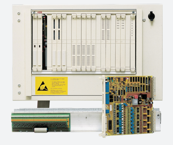
The S100 I/O process interface
modules for Advant Controller
400 series process controllers
come with connection units,
simplifying cable termination and
keeping noise and destructive
spikes away from the central
electronics.
S100 I/O is the central process interface for Advant
Controller 400 series process controllers. Thanks to
built-in cablemarshalling facilities and parallel
communication with the host controller, it is the
right choice for centralized I/O systems and
high-speed applications.
The range of process I/O modules is complete,
consisting of general purpose digital and analog
inputs and outputs and special interfaces for special
tasks. These specials include pulse counting,
frequency measuring, positioning, motor speed
control and communication with other controllers.
All I/O modules provide simple interfacing, accurate -
yet fast - control, and easy integration of individual
loops into a comprehensive plant-wide control
and supervision system.
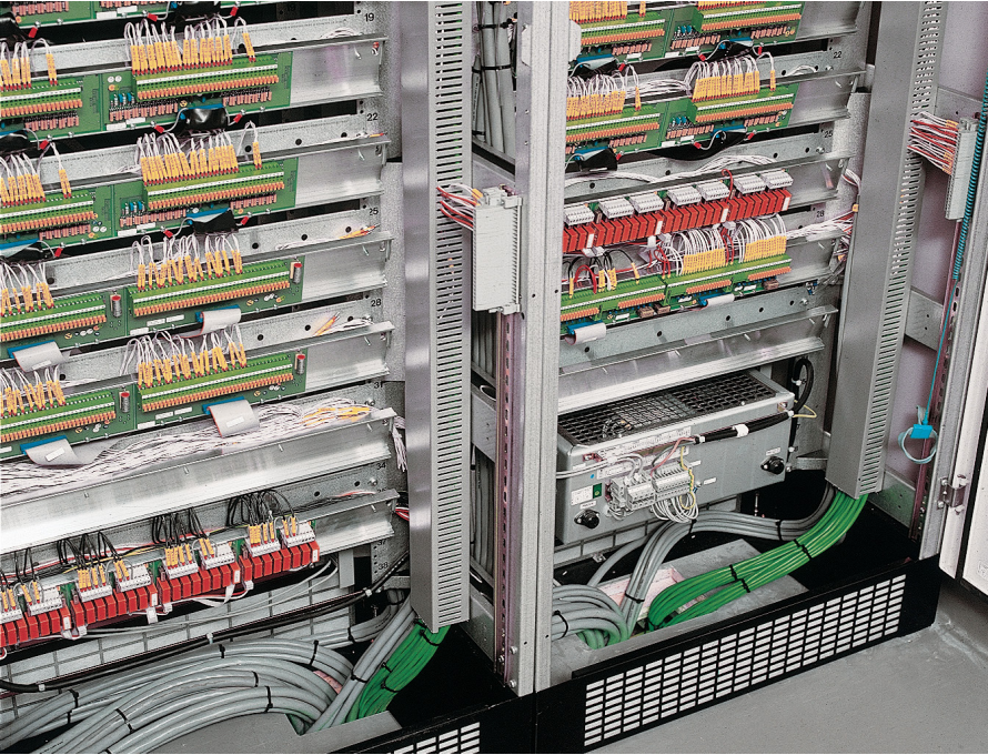
The interface modules connect to the process
through screw terminals on connection units
normally installed inside, at the back of the cabinet.
This solution keeps noise and destructive voltage
spikes away from the central electronics and
provides a neat and tidy process interface that is
easy to maintain.
Prefabricated cables interconnect modules with
connection units. The cables come in different
lengths, permitting termination and marshalling
in controller cabinets, in adjacent cabinets, or in
cabinets a greater distance away.
There are connection units that support signaloriented or device-oriented field wiring. The former
means that field wires with the same electrical
characteristics (e.g. all 24 V d.c. inputs) are grouped
and terminated together, the latter that field wires
to/from the same field devices are grouped and
terminated together. The combination means
maximum installation flexibility.
On-board processing capabilities
The process I/O modules are “intelligent” in the sense
that module-related signal and data processing is
performed on board as opposed to centrally, by the
CPU of the host controller. Time tagging of events,
filtering and gain control are some examples of
board-level tasks. This functional distribution improves
real-time performance and reliability of the system
as a whole and maintains processing capacity when
the system is expanded.
Comprehensive self-diagnostics
Comprehensive self-diagnostics continuously monitor
the modules and report any errors through LEDs on
the module fronts and through alarm messages and
indications to process operator stations.
Malfunctioning inputs can be disabled and simulated
by manual entry while failing outputs are deactivated
or driven to a predetermined safe state automatically.
All I/O modules can be replaced while the system is in
service. Some modules can even be arranged, trans parently into dually redundant configurations
forenhanced availability.
High disturbance immunity
All modules conform to the highest standards of
electromagnetic noise immunity and satisfy the
requirements of the EU directives 2014/30/EU and
2014/35/EU. For the above reasons, S100 I/O is likely
to be the best help you can get for putting your con trol system in touch with your field devices.
Analog inputs
±10 V/±20 mA
• 16 ch., differential, 12 bits + sign resolution, CMV ≤ 50 V,
CMRR > 100 dB (at 50 Hz), (DSAI 130A)
0…+10 V/0…+20 mA
• 32 ch. (DSAI 133A1), single-ended, 12 bits resolution
-100…+320/-200…+640°C
• 31 measuring + 1 reference ch., Pt100, 3-wire, 12 bits + sign
resolution, (DSAI 146)
Thermocouples
• 14 measuring, 2 reference + 1 compensation ch., measuring
ranges B, C, E, J, K, R, S and T with grounded or floating output
signals, 12/13 bits + sign resolution, CMV ≤ 16 V,
CMRR > 100 dB (at 50 Hz), (DSAI 155A)
Analog outputs
±10 V/±20 mA
• 8 ch., 12 bits + sign resolution, galvanically isolated, (DSAO 120A)
0…20 mA
• 16 ch., 12 bits resolution, (DSAO 130A)
Analog inputs/outputs
0…+10 V/0…+20 mA
• 8 input ch., single-ended, 12 bits resolution;
• 8 output ch., 12 bits resolution (DSAX 110A1)
Digital inputs
24 V d.c.
• 32 ch. in 4 groups, optoisolated, read by scanning or interrupts
(DSDI 110AV12/DSTD 190V1,
DSDI 110AV12/DSTD 150A, with screw terminals or
DSDI 110AV12/DSTD 195, galvanic isolated)
24/48 V d.c.
• 32 ch. in 4 groups, optoisolated, read by scanning or interrupts
(DSDI 110AV12/DSTD 196P)
48 V d.c.
• 32 ch. in 4 groups, optoisolated, read by scanning or interrupts
(DSDI 120AV12/DSTD 190V1 or
DSDI 120AV12/DSTD 150A, with screw terminals)
110 V d.c. or 120 V a.c
• 32 ch. in 4 groups, optoisolated, read by scanning or interrupts
(DSDI 110AV12/DSTD 197)
230 V a.c.
• 32 ch. in 4 groups, optoisolated, read by scanning or interrupts
(DSDI 110AV12/DSTD 198)
Digital outputs
24…250 V a.c. or d.c.
• 32 ch., (DSDO 115A/DSTD 108P), relay contacts.
Relay data: Load current; max. 3 A, min 0,1 A at 24 V d.c. or
2,5 VA a.c. Breaking capacity a.c max 720 VA at cos Φ > 0.4;
d.c. max 44 W at L/R <40 ms.
• 32 ch., (DSDO 115A/DSTD 108LP), relay contacts.
Relay data: Load current; max. 200 mA, min 1 mA, 0.05 VA. Breaking capacity a.c max 5 VA at cos Φ > 0,4; d.c. max. 5 W at L/R
<40 ms.
24 V d.c.
• 32 ch., short-circuit-proof transistor, max. 500 mA, (DSDO 115A)
• 32 ch., (DSDO 115A/DSTD 109P) short-circuit-proof transistor,
max. 2 A
Pulse counting and positioning
5/12/24 V d.c.
• 12 ch., max. 10 kHz, (DSDP 150)
Complete interface (DSDP 140A) for one positioning loop,
consisting of:
• Pulse inputs: 3 (A, B and STROBE), ±15 mA, max. 80 kHz DI/DO:
24 V d.c. DO max. 150 mA AO: ±10V/±20 mA, 11 bits resolution
Complete interface (DSDP 170) for
• 4 position transducers, each circuit consisting of: Pulse inputs:
3 (A, B and STROBE), 5/12/24 V or ±15 mA d.c., max. 2.5 MHz
DI/DO: 24 V d.c. DO max.150 mA
Digital speed control of motors
Complete interface (DSDC 111) for one d.c. motor, consisting of:
3 pulse inputs for A, B and STROBE
1 DI, 24 V d.c.
1 DO, 24 V, 150 mA d.c.
1 AO, ±10 V/±20 mA, 12 bits resolution
1 Supports transparent dual redundancy.
2 Digital Input Modules with Event detection.
- YOKOGAWA
- Reliance
- ADVANCED
- SEW
- ProSoft
- WATLOW
- Kongsberg
- FANUC
- VSD
- DCS
- PLC
- man-machine
- Covid-19
- Energy and Gender
- Energy Access
- Renewable Integration
- Energy Subsidies
- Energy and Water
- Net zero emission
- Energy Security
- Critical Minerals
- A-B
- petroleum
- Mine scale
- Sewage treatment
- cement
- architecture
- Industrial information
- New energy
- Automobile market
- electricity
- Construction site
- HIMA
- ABB
- Rockwell
- Schneider Modicon
- Siemens
- xYCOM
- Yaskawa
- Woodward
- BOSCH Rexroth
- MOOG
- General Electric
- American NI
- Rolls-Royce
- CTI
- Honeywell
- EMERSON
- MAN
- GE
- TRICONEX
- Control Wave
- ALSTOM
- AMAT
- STUDER
- KONGSBERG
- MOTOROLA
- DANAHER MOTION
- Bentley
- Galil
- EATON
- MOLEX
- Triconex
- DEIF
- B&W
- ZYGO
- Aerotech
- DANFOSS
- KOLLMORGEN
- Beijer
- Endress+Hauser
- schneider
- Foxboro
- KB
- REXROTH
- YAMAHA
- Johnson
- Westinghouse
- WAGO
- TOSHIBA
- TEKTRONIX
- BENDER
- BMCM
- SMC
- HITACHI
- HIRSCHMANN
- XP POWER
- Baldor
- Meggitt
- SHINKAWA
- Other Brands
- UniOP
- KUKA
- IBA
- Beckhoff
- ADLINK
51
-
Beckhoff EP9224-0037 - 4-Channel Power Distribution Box EtherCAT
-
Beckhoff CX2900-0026 - Solid State Flash Memory Card 20GB CFast
-
Beckhoff BK7500 - SERCOS Interface Fieldbus Bus Coupler Terminal
-
Beckhoff Ep2328-0002 - 4-Channel Input 4-Channel Output EtherCAT Box IP67
-
Beckhoff CX1020-0111 - Controller Kit Combo Interface Modules
-
B&R X20AI2237 - X20 System Analog Input Interface Module
-
Beckhoff CP2221-0010 - Multi-Touch Built-In Panel PC Touchscreen
-
Beckhoff CX1500-M310 - Fieldbus Master Interface Module 24V
-
Beckhoff CX2100-0904 - Power Charging Module Smart UPS Extension
-
Beckhoff CP3918-0000 - Multi-Touch Control Panel 18.5-Inch Monitor
-
Beckhoff CP2915-0000 - 15-Inch Multi-Touch Built-In Control Panel
-
Beckhoff CP7037-1027 - HMI Industrial Control Panel Built-In PC
-
Beckhoff EL3152 - 2-Channel Analog Input Terminal 4-20mA EtherCAT
-
Beckhoff CP6607-0000-0020 - 5.7-Inch Built-In Panel PC HMI Touch
-
Beckhoff EJ1809-0000 - 16-Channel Digital Input Pluggable Signal Level Terminal
-
Beckhoff AM8563-0N10-0000 - Synchronous Servo Motor
-
Beckhoff AX2006-S60600-520 - Compact Servo Drive Inverter
-
Beckhoff AM8053-0K20-0000 - Servo Motor with Planetary Gearbox AG3210
-
Beckhoff AM8042-0FH1-0000 - Synchronous Servo Motor
-
Rexroth R911338600 - IndraControl V HMI Terminal Beckhoff PCI Card FC9002
-
Beckhoff AX5125-0000 - 3 Phase Industrial Servo Drive 1000Hz
-
Beckhoff EP2328-0002 - 4-Channel Digital Input 4-Channel Output EtherCAT Box
-
B&R 7CP476-02 - System 2005 RTD CPU Module 3IF681.86 Interface
-
Beckhoff AX8620-0000-0000 - Power Supply Module Axis Drive System
-
Beckhoff CX1010-0111 - PLC Module CPU Controller 24V
-
Beckhoff AM8043-0H10-0000 - Synchronous Servo Motor
-
Beckhoff C6240-1009 - Control Cabinet Industrial PC Mainframe
-
Beckhoff BX8000-0000 - Bus Terminal Controller HW 4.4 Standalone
-
Beckhoff CP7721-1089-0020 - 12.1-Inch Touch Screen HMI Panel PC
-
Beckhoff CP7132-0001 - Industrial Built-In Panel PC Screen
-
Beckhoff CP2912-0010 - Multi-Touch Built-In Control Panel Display
-
Beckhoff CP2915-0000 - 15-Inch Multi-Touch Built-In Control Panel
-
Beckhoff AM8532-1EN0-0000 - Synchronous Servo Motor
-
Beckhoff AX5203-0000 - 2-Channel Digital Compact Servo Drive
-
Beckhoff CX2020-0141 - Embedded PC Core CPU Module
-
Beckhoff CP6832-0002-0010 - Built-In Industrial Control Panel Display
-
Beckhoff CX5020-0112 - Embedded PC CPU Control Module
-
Beckhoff CX5140-0175 - 4GB Embedded PC CPU Unit 24V
-
Beckhoff EL3681-0030 - Digital Multimeter Calibration Terminal EtherCAT
-
Beckhoff CP7201-1000-0000 - Industrial PC Touch Screen HMI Monitor
-
Beckhoff CP7232-1001-0000 - Industrial Panel PC Touch Screen
-
Beckhoff C6930-1032-0040 - Control Cabinet Industrial PC System
-
Beckhoff AX5125-0000 - 3 Phase Industrial Servo Drive 1000Hz
-
Beckhoff CP3916-1424-0000 - Multi-Touch Built-In Control Panel
-
B&R 1900071142 - Lemoine Fieldbus Communication Interface Module
-
Beckhoff EL2872 - 16-Channel Ribbon Cable Digital Output Terminal
-
Beckhoff CX2030-0120 - Embedded PC CPU Base Module Controller
-
Beckhoff CP3919-0000 - 19-Inch Multi-Touch Control Panel Touchscreen
-
Beckhoff AX5101-0000-0202 - Servo Driver Compact Intelligent Drive 180V
-
Beckhoff CX5130-0135 - Embedded PC Controller Module
-
Beckhoff CP3719-1061-0010 - Multi-Touch Panel PC Outer Housing Enclosure
-
Beckhoff CP3919-1033-0000 - 19-Inch Touch Industrial Panel Keyboard
-
Beckhoff CX5020-0111 - Embedded PC PLC CPU Module
-
Beckhoff FC5102-0000 - 2-Channel CANopen PCI Control Board Card
-
Beckhoff CX9001-1101 - Embedded PC CPU Network I/O System Module
-
Beckhoff CX1100-0920 - Smart Position Sensor Interface Module
-
B&R 4P3040.01-490 - Operator Panel PLC Interface Communication Module
-
Beckhoff CP2612-0000 - Dual-Touch Built-In Panel PC HMI
-
Beckhoff CP7002-1043-0010 - Touchscreen Display HMI Panel Terminal
-
Beckhoff CX9020-0115 - Embedded PC Controller Module
-
Beckhoff CX5140-0155 - 4GB Embedded PC CPU Module Die Industry
-
B&R 7DI435.7 - System 2005 Universal Digital Input Output Module
-
Bihl+Wiedemann BWU1568 - AS-i Master to Profibus Gateway Module
-
Beckhoff C6920-0070 - Control Cabinet Industrial PC 8GB Win 10
-
B&R X20AI2322 - 2-Channel Temperature Analog Input Module
-
Beckhoff CP2912-0000 - 12-Inch Touchscreen Display Monitor Screen
-
Beckhoff CP6022-1001-0010 - 15-Inch Built-In Control Panel
-
Beckhoff AM8031-0D10-0000 - Synchronous Servo Motor
-
Beckhoff CX5010-0111 - Embedded PC Controller CPU Module
-
Beckhoff CP7232-1000-0000 - Industrial Panel PC Touch Display Screen
-
Beckhoff CP7802-0011-0000 - 15-Inch Industrial Touchscreen Control Panel
-
Beckhoff C6320 - Control Cabinet Industrial PC
-
Beckhoff CX1030-0012 - Basic CPU Module Windows CE 6.0
-
Beckhoff CP2919-0000 - Installation Multi-Touch Control Panel
-
Beckhoff CX1020-0000 - Controller Set Stack System Pack
-
B&R 3DO480.6 - System 2005 Digital Output Module
-
Beckhoff EL3101 - 1-Channel Analog Input Terminal Differential +/-10V
-
Beckhoff AX8108-0200-0000 - Axis Feed Module Servo Drive
-
Beckhoff CP7802-1241-0010 - 15-Inch Industrial Touchscreen Control Panel
-
Beckhoff FC2002-0000 - 2-Channel Lightbus Data Acquisition PCI Card
-
Beckhoff CX5120-0155 - 2GB Embedded PC Intel Atom Controller
-
Beckhoff Cx9020-0111 - 1GB Basic CPU Module Embedded PC
-
Beckhoff CP6901-0001-0000 - 12-Inch Economy Built-In Control Panel
-
Beckhoff CX9020-0111 - Embedded PC CPU Basic Module
-
Beckhoff CX5130-0100 - 4GB Embedded PC CPU Module
-
Beckhoff CP2715-0010 - Multi-Touch Built-In Panel PC
-
Beckhoff CX2033-0175 - Embedded PC CPU Module Core i7
-
Beckhoff CP7201-1000-0000 - 12-Inch Touchscreen Panel PC AMAT Green Box
-
Beckhoff EL4038 - 8-Channel Analog Output Terminal 0-10V EtherCAT
-
Beckhoff CP6802-0000-0000 - Built-In Control Panel HMI Screen
-
Beckhoff AM8042-0F21-0000 - Synchronous Servo Motor
-
Beckhoff CX5120-0141 - Embedded PC Basic Controller Module
-
Beckhoff C6930-0050 - Control Cabinet Industrial PC System
-
Beckhoff CP6831-0002-0000 - Built-In Industrial Control Panel
-
Beckhoff CP6919-0001-0000 - Built-In Control Panel Display Unit
-
Beckhoff CP7201-1019-0030 - Built-In Panel PC HMI Monitor Screen
-
Beckhoff CP6809-0001-0000 - 6.5-Inch Touch Panel ELO Accutouch HMI
-
Beckhoff CX1020-0000 - Control Kit Combo Stack Units
-
Beckhoff cp3918-1012-0000 - 18.5-Inch Multi-Touch Control Panel
-
Beckhoff CX5140-0123 - 4GB Embedded PC CPU Module
-
Beckhoff C3230TP - Industrial PC Rackmount Workstation
-
Beckhoff CP6801-1006-0010 - Touch Panel HMI Display Unit
-
Beckhoff CX8010 - Embedded PC Controller Module
-
Beckhoff CP7011-0001 - Control Panel CRT Operator Pendant Monitor HMI
-
Beckhoff CX1010-0111 - Embedded PC CPU PLC Module 24V
-
Beckhoff CP2915-0000 - 15-Inch Multi-Touch Built-In Control Panel
-
Beckhoff CP7802 - Industrial Touch Screen Control Panel Monitor
-
Siemens 6AV7452-1AB00-0FB0 - Industrial PC Panel 877 Beckhoff PCI Cards
-
Beckhoff CP2612-0000 - Dual-Touch Integrated Panel Monitor Screen
-
Beckhoff CX5140-0175 - Embedded PC Core Controller
-
Beckhoff Cp6202-0001-0010 - Economy Built-In Panel PC System
-
Beckhoff C6320-0010 - Control Cabinet Industrial PC Unit
-
Beckhoff CP2919-0000 - Multi-Touch Built-In Control Panel Screen
-
Beckhoff CX9020-0111 - Embedded PC CPU Controller Module
-
B&R 3BP151.41 - System 2005 Backplane Base Module
-
Siemens 6AV7452-1AB00-0FB0 - Panel PC 877 with Beckhoff Communication Cards FC3101 FC7501
-
Beckhoff CX9001-1101 - Embedded PC System Fieldbus Module Bundle
-
Beckhoff CX1001-0122 - CPU Module PLC Controller 128MB RAM
-
Beckhoff CX5130-0175 - Embedded PC CPU Module Intel Atom Storage Card
-
Beckhoff C6140 - Industrial PC Tower Casing Pent 4 System
-
Beckhoff CX5020-0120 - Embedded PC Controller Core Module
-
Beckhoff C6017-0010 - Ultra-Compact Industrial PC
-
Beckhoff CP6809-0000-0000 - 6.5-Inch Industrial Panel Control Display
-
Beckhoff AX5021-0000-0000 - Brake Chopper Module Axis System
-
Beckhoff AM8031-0D10-0000 - Synchronous Servo Motor
-
Beckhoff CX8010 - Embedded PC Microcontroller Module
-
Beckhoff CP6202-1070-0070 - Built-In Panel PC HMI Touchscreen
-
Beckhoff C6920-0000 - Control Cabinet Industrial PC Module

K-JIANG

Add: Jimei North Road, Jimei District, Xiamen, Fujian, China
Tell:+86-15305925923