
K-WANG


TEKTRONIX 5A22N Differential Amplifier
Core features:
Bandwidth: Maximum DC to 1MHz, bandwidth can be limited by HF-3dB (high frequency) and LF-3dB (low frequency) switches to improve signal-to-noise ratio;
Deflection coefficient: The knob skirt edge emits light and displays, supporting automatic scaling of 10X encoding probes;
Other: High common mode rejection ratio (CMRR), variable DC offset, suitable for displaying small signals at large DC levels.
TEKTRONIX 5A22N Differential Amplifier
Operation Instructions (Section 1)
1. Instrument description
Positioning: High gain differential amplifier plug-in unit, used for 5100 series oscilloscopes, can directly couple input to achieve high sensitivity.
Core features:
Bandwidth: Maximum DC to 1MHz, bandwidth can be limited by HF-3dB (high frequency) and LF-3dB (low frequency) switches to improve signal-to-noise ratio;
Deflection coefficient: The knob skirt edge emits light and displays, supporting automatic scaling of 10X encoding probes;
Other: High common mode rejection ratio (CMRR), variable DC offset, suitable for displaying small signals at large DC levels.
2. Panel controls and interfaces (key functions)
Control/Interface Function Description
Display switch plugin working status (only valid for vertical cabin), when turned on, the knob skirt light is on
POSITION adjusts the trajectory position on the screen
HF -3dB/LF -3dB - HF -3dB: 1-3-10 sequence with 7 levels (0.1kHz-1MHz), reducing the upper bandwidth limit and improving signal-to-noise ratio
-LF-3dB: 1-10-100 sequence with 7 levels (DC-10kHz), limited to 2Hz during AC coupling; adjustable DC offset in DC OFFSET level
VOLTS/DIV - Calibration mode: 18 levels 1-2-5 sequence, 10 μ V/Div to 5V/Div (accuracy 2%)
-Variable gear: Non calibrated continuous adjustment, range extended to 12.5V/Div
DC OFFSET (COARSE/FINE) requires LF-3dB to be placed in the DC OFFSET mode to achieve display adjustment of small signals at large DC levels
STEP ATTEN DC BAL balanced input amplifier to reduce trajectory offset during VOLTS/DIV switching
Input coupling button (AC/DC/GND/PRE CHG) - AC: capacitive coupling (blocking DC); DC: direct coupling
-GND: Input ground (disconnect signal); PRE CHG: Press AC+GND to pre charge the coupling capacitor to the signal DC level
+/-Input interface BNC interface,+positive signal deflects upwards, - positive signal deflects downwards; Equipped with a 10X encoded probe ring
3. Basic operation steps
Installation and startup:
Insertion: Align the plug-in guide rail with the 5100 series module compartment (priority vertical compartment: center/left; X-Y operation can be inserted into the horizontal compartment), and the panel should be level with the oscilloscope;
Power on: Adjust the oscilloscope brightness to the lowest level → Power on → Preset time base (2ms/Div) and trigger (automatic trigger).
Initial setup:
Set PLAY to ON,+/- input coupling to DC+GND, POSITION and STEP ATTEN BAL to median, HF/LF-3dB to full bandwidth, VOLTS/DIV to 50mV/Div, and variable gear to CAL (clockwise to bottom).
Preheating and trajectory adjustment:
Preheating: Short term DC measurement for 5 minutes, long-term DC measurement for 15 minutes;
Adjust the brightness to normal, and the trajectory should be near the center of the scale. Use POSITION to move the trajectory to 2 grids below the centerline.
Example of signal measurement:
Single ended DC coupling:+input connected to 400mV peak to peak calibration signal → release+GND → display 4 grid square waves (bottom alignment step 3 reference line);
Single ended AC coupling: POSITION moves the trajectory from bottom to center → presses AC → the trajectory shifts downward by about 2 grids (to the average value);
Differential AC coupling:+/- input connected to dual input cable → - input set to AC → display straight line (common mode signal suppressed).
4. Key precautions
Input protection: The maximum voltage of the input FET gate is ± 12V (diode clamp), and the input fuse will melt when the signal source current exceeds 1/16A;
Pre charge (PRE CHG): When measuring AC signals containing DC components, first connect the AC+GND signal → wait for 1 second for charging → release GND to avoid damaging the signal source due to coupling capacitor charging current;
High impedance input: When VOLTS/DIV is in the 50mV-10 μ V range, removing the circuit board jumper can disconnect the 1M Ω ground resistor, achieving high impedance input (requiring the signal source to provide a DC path for FET gate current).
5. Electrical characteristics (core parameters)
Specific parameters of characteristics
Bandwidth (-3dB) - DC coupling: DC to ≥ 1MHz (independent of deflection coefficient)
-AC coupling: 2Hz to ≥ 1MHz
Common mode rejection ratio (CMRR) - DC coupling: 10 μ V/Div-0.1mV/Div range ≥ 100dB (DC-30kHz, 20Vp-p sine wave); 0.1V/Div-5V/Div mode ≥ 50dB (100Vp-p sine wave)
-AC coupling: ≥ 80dB at 5kHz and above, reduced to 50dB at 10Hz
DC offset range -10 μ V/Div-50mV/Div range: ± 0.5V
-100mV/Div-5V/Div mode: ± 50V
Input RC 1M Ω (± 0.1%) in parallel at approximately 47pF
Maximum input voltage DC coupling: 10V (DC+peak AC) (10 μ V-50mV range); 350V (DC+peak AC) (100mV-5V range)
-AC coupling: 350VDC+10V peak AC (10 μ V-50mV range, pre charged); 350V (DC+peak AC) (100mV-5V range)
Noise at full bandwidth (DC-1MHz) ≤ 20 μ V (25 Ω source resistance, tangent measurement)
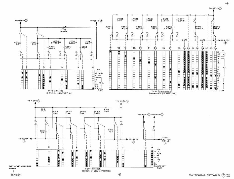
Working principle (Section 2)
1. Overall block diagram path
Signal → Input coupling (AC/DC/GND) → Input attenuator (1X/100X, frequency compensation) → Pre amplifier (differential structure, floating ground power supply) → Low frequency limiting circuit (LF-3dB switching) → Gain switching stage (VOLTS/DIV control) → Offset generator (DC OFFSET) → Isolation stage (emitter follower) → Output amplifier (push-pull structure, POSITION adjustment) → Trigger signal amplifier (output to time base plugin, 0.25V/display panel).
2. Analysis of core circuit modules
Input attenuator:
Attenuation ratio: VOLTS/DIV 0.1V-5V range with 100X attenuation, 10 μ V-50mV range with 1X attenuation;
Features: Frequency compensation, maintaining 1M Ω//47pF input characteristics, balancing common mode signals through R132 (Atten DC CMR).
Pre amplifier:
Structure: Two identical operational amplifiers form a differential circuit (Q150A/B, Q190A/B, Q200A/B);
Floating power supply: composed of Q170/Q176 (constant current source) and VR173/175/176 (Zener transistor), it maintains the stability of the amplification device operating point and improves CMRR as the common mode signal changes;
Gate current compensation: Regulate R121/R127 to offset FET gate leakage current (≤ 100pA) and avoid high-sensitivity offset (such as 100pA × 1M Ω=100 μ V offset in 10 μ V/Div mode, which may cause trajectory offset screen).
DC offset generator:
Structure: Q240/Q244/Q246A/B form a voltage comparator, with VR251 (transistor) providing a reference voltage;
Function: By adjusting COARSE (R260) and FINE (R268), offset current is generated to cancel the DC component of the input signal, with a maximum cancellation of 0.5V.
Output amplifier:
Structure: Push pull amplifiers Q348/Q352, R351 (GAIN) adjust the total gain to match the requirements of the host;
Position adjustment: Q360/Q362 (positioning current drive), R360 (POSITION) changes the current to adjust the static position of the CRT beam.
Calibration (Section 3)
1. Calibration prerequisites and preparations
Applicable scenarios: After instrument maintenance, long-term use (component aging) leads to accuracy deviation;
Environmental requirements: Temperature of 20-30 ℃, preheating for 20 minutes;
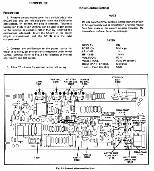
Equipment disassembly: Remove the left protective cover of 5A22N and the left panel of 5100 series oscilloscope (or use plug-in extender 067-0645-00);
Initial settings: Set the 5A22N control to POSITION median LF-3dB=1Hz、HF-3dB=1MHz、VOLTS/DIV=50mV、 Variable gear=CAL,+/- input=DC+GND, STEP ATTEN BAL median; The 5B10N time base is set to automatic triggering,+slope, and AC coupling.
2. Required testing equipment (including accessories)
Specific requirements/model examples for equipment types
Oscilloscope System 5100 Series (including 5B10N Time Base Plugin)
Constant amplitude sine wave generator frequency 2Hz-1MHz, output 0.5V-40Vp-p (such as General Radio 1310-B)
Standard amplitude calibrator 1kHz square wave, output 5mV-50V, accuracy ± 0.25% (recommended 067-0502-01)
Accessories - Coaxial Line: 50 Ω, 42 inches, BNC(012-0057-01)
-Dual input cable: matching signal path, BNC(067-0525-00)
-1000:1 voltage divider: accuracy ± 0.2% (067-0529-00)
-Input RC Normalizer: 1M Ω× 47pF (067-0541-00)
-Serial terminal: 50 Ω, accuracy ± 2% (011-0049-01)
3. Key Calibration Steps (Core 8 Steps)
Step attenuator balance:
R292 (AC STEP ATTEN BAL): Switch between VOLTS/DIV 50mV-0.1V to minimize trajectory offset;
Adjust R318 (VAR BAL): Shift the variable gear from CLOCKWISE to COUNTERCLOCKWISE to minimize trajectory deviation;
Adjust R250 (COARSE DC BAL): Set LF-3dB to DC, switch VOLTS/DIV 50mV-0.1V, and minimize trajectory offset.
Gate current regulation:
+Input to 50 Ω terminal → LF-3dB=DC → Release+GND → Switch+AC, adjust R121 (+GATE CURRENT), minimize trajectory offset;
-Input to 50 Ω terminal → press+GND → release - GND → switch - AC, adjust R127 (- GATE CURRENT), minimize trajectory deviation.
Attenuator DC common mode rejection:
Release+/- GND → VOLTS/DIV=0.1V →+/- Input through dual cables connected to a 50V square wave (calibrator) → Adjust R132 (ATT DC CMR) to display the minimum amplitude.
Input compensation:
-GND pressed ->VOLTS/DIV=50mV ->+input connected to 0.5V square wave (normalized by RC) ->C118 adjusted (Atten Time Constant), with the best square wave front;
Similarly, input C148, C145, C142.
Amplifier gain calibration:
VOLTS/DIV=10mV →+input connected to 50mV square wave → adjust R351 (GAIN), display amplitude exactly 5 grids;
Turn the variable gear to COUNTERCLOCKWISE, with a display amplitude of<2 grids, and then turn it back to CAL.
VOLTS/DIV accuracy check:
VOLTS/DIV=5V →+input connected to 20V square wave (through 1000:1 voltage divider X1 gear) → gradually decrease VOLTS/DIV, synchronously adjust the calibrator output, ensure display of 4-5 grids, accuracy ± 2%;
VOLTS/DIV=5mV gear → voltage divider set X1000 → calibrator output 20V → HF-3dB=10kHz → repeat the above checks.
Common mode rejection ratio (CMRR) calibration:
Release - GND → VOLTS/DIV=10mV →+/- input connected to 20Vp-p, 50kHz sine wave → adjust C160 (CMR 2), display minimum;
VOLTS/DIV=50 μ V → Time base=10 μ s/Div → Adjust C220 (CMR 1), display minimum;
LF-3dB=0.1kHz → switch to C210 (CMR 3), display minimum, repeat until there is no interaction effect.
Bandwidth calibration:
-GND pressed → VOLTS/DIV=1mV → LF-3dB=DC → Time base=1ms/Div →+input connected to 1kHz, 8-grid sine wave → Generator output 1MHz → C330 adjusted, display amplitude reduced to 5.6 grid (-3dB point).
Drawings and Parts List (Section 4)
1. Symbols and reference identification rules
Component symbol: Following ANSI Y32.2-1970 standard, logical symbol follows MIL-STD-806B (positive logic);
Reference identification prefixes: C=capacitor, R=resistor, Q=transistor, CR=diode, F=fuse, J=fixed connector, S=switch, VR=voltage regulator (transistor), etc.
2. Core Parts List (Example)
Part Type Reference Identification Tektronix Part Number Specification Description
Capacitor C103 283-0002-00 0.01pF, ceramic, 500V
Capacitor C133 283-0626-00 1800pF, mica, 5%
Resistance R120 322-0481-07 1M Ω, 1/4W, 1/10%
Resistance R121 311-1223-00 250 Ω, variable
Transistors Q150A/B 151-1027-00 silicon FET, replaceable with D/2N4394 or FD1392
Transistors Q103/Q105 151-0347-00 silicon NPN, replaceable with 2N5551
Diode VR138 152-0520-00 Zener diode, 1W, 12V, replaceable with UZ8712 or HW12B
Switch A10 (LF-3dB) 105-0310-00 cam switch
Switch S280 (VOLTS/DIV) 105-0309-00 cam switch
Circuit board A1 670-1894-00 main circuit board component
- YOKOGAWA
- Reliance
- ADVANCED
- SEW
- ProSoft
- WATLOW
- Kongsberg
- FANUC
- VSD
- DCS
- PLC
- man-machine
- Covid-19
- Energy and Gender
- Energy Access
- Renewable Integration
- Energy Subsidies
- Energy and Water
- Net zero emission
- Energy Security
- Critical Minerals
- A-B
- petroleum
- Mine scale
- Sewage treatment
- cement
- architecture
- Industrial information
- New energy
- Automobile market
- electricity
- Construction site
- HIMA
- ABB
- Rockwell
- Schneider Modicon
- Siemens
- xYCOM
- Yaskawa
- Woodward
- BOSCH Rexroth
- MOOG
- General Electric
- American NI
- Rolls-Royce
- CTI
- Honeywell
- EMERSON
- MAN
- GE
- TRICONEX
- Control Wave
- ALSTOM
- AMAT
- STUDER
- KONGSBERG
- MOTOROLA
- DANAHER MOTION
- Bentley
- Galil
- EATON
- MOLEX
- Triconex
- DEIF
- B&W
- ZYGO
- Aerotech
- DANFOSS
- KOLLMORGEN
- Beijer
- Endress+Hauser
- schneider
- Foxboro
- KB
- REXROTH
- YAMAHA
- Johnson
- Westinghouse
- WAGO
- TOSHIBA
- TEKTRONIX
- BENDER
- BMCM
- SMC
- HITACHI
- HIRSCHMANN
- XP POWER
- Baldor
- Meggitt
- SHINKAWA
- Other Brands
- UniOP
- KUKA
- IBA
- Beckhoff
-
ADLINK CPCI-6860A - 51-31310-OB10 industrial motherboard CompactPCI SBC
-
ADLINK AmITX-SL-G-H110 - 51-7A104-0A30 Mini-ITX Industrial Motherboard
-
ADLINK PXI-2005-003 - CPCI Industrial PC Data Acquisition Card Multi-Function DAQ
-
ADLINK DININ-814M - 51-14032-0A3D SCSI-100P cable connection Interface Terminal Board
-
ADLINK CPCI-3920NA/C2D15/M1G - 3U CompactPCI Intel Core 2 Duo Single Board Computer
-
ADLINK PCIE-8560 - 51-18014-0A20 Communication Card High Speed DAQ
-
ADLINK PCI-C154+ - Motion Control Card 4-axis Motion Controller Board
-
ADLINK PCI-RTV24 - image capture card Analog Video Frame Grabber
-
ADLINK NuPRO-842LV/P - 51-41360-0B30 Industrial Motherboard CPU Board
-
ADLINK cBP-3208/3208R - CPCI Board 3U 8-Slot CompactPCI Backplane
-
ADLINK PCI-8164 - 4-Axis Motion Controller PCI Card 51-12406-0A40
-
ADLINK PCIe-GIE64+ - 4-CH GigE Vision PoE+ Frame Grabber Video Capture Card
-
ADLINK CPCI-6860 / 6860A - CompactPCI Dual Xeon Single Board Computer
-
ADLINK IEC-915GV - REV 1.1 Industrial motherboard CPU Board
-
ADLINK ND-6520 - Technology RS-232 to RS-422RS-485 Converter NuDAM Module
-
ADLINK RTV-24 / PCI-MP4S - 51-12519-1C30 4-Channel Real Time Video Capture Board
-
ADLINK cPCI-6910 / cPCI-6910AM/M1G - cPCI-6910AM/DXL16/M1G/S80G(G)-3120 BOARD CompactPCI SBC
-
ADLINK NUPRO-A40H - Linghua 51-41807-1A30 Industrial Control Computer Motherboard
-
ADLINK USB-3488A - USB to GPIB INTERFACE USB-3488A(G) Controller Module
-
ADLINK PCI-8134A - motion control card 4-Axis Controller Card
-
ADLINK PCI-7432 - Board 32-Channel input / 32-output Isolated Digital I/O PCI Card
-
ADLINK PCI-8134A - 51-12421-0A10 motion controller card tested
-
ADLINK LPCIe-7230 - 32 CH Isolated Input/output Card 2 Interrupts Low Profile PCIe
-
ADLINK NuPRO-E340 - industrial computer motherboard 51-47807-0A30 PICMG 1.3 SHB
-
ADLINK PCI-7434 - High-speed Digital Acquisition Card 64-CH Isolated DO Card
-
ADLINK NuPRO-E330 - 51-41805-0A20 Indsutrial Board SHB Single Board Computer
-
ADLINK PCI-7248 - OPTO-22 48 CHANNEL DIO DIGITAL TTL/DTL I/O 51-12006-0A40 GP
-
ADLINK PCI-8134 - Motion control card 4-Axis Controller Card
-
ADLINK AMP-208C - Movimiento Control Tarjeta 51-12420-1A20 W/Expansión & Breakout
-
ADLINK PCI-8164 - 51-12406-0A40 PCB Board 4-Axis Motion Controller Card
-
ADLINK DIN-68Y-SGII / DIN-68M-J3A - Terminal Board Connector Interface Block
-
ADLINK PCIe-7432 - Technology 51-18402-0A10 PCIe Card With High Input Range
-
ADLINK PCI-8144 / PCI-8144N - Motion control card 4-Axis Stepper Controller Card
-
ADLINK HSL-HUB3/REPEATER - HIGH SPEED LINK EXTENSION MODULES Distributed Hub Module
-
ADLINK ND-6017 - Data Logging + Acquisition 8CH A/D input Mod NuDAM Module
-
ADLINK LPCIe-7250 - data acquisition card Low Profile 8-CH Relay Output Card
-
ADLINK PCI-7432 - I/O card 64-CH Isolated Digital Input Output PCI Card
-
ADLINK IMB-M43H - industrial control computer motherboard Q87 Chip Micro-ATX
-
ADLINK MP-C154 - Motion control Card 4-Axis Motion Controller Board
-
ADLINK PCI-RTV24 - image capture card Video Frame Grabber Card
-
ADLINK PCI-7250 - 8-CH Relay Output & 8-CH Isolated DI Card
-
ADLINK PCI-6308V - 8-CH 12-Bit Isolated Analog Output PCI Card PCB-I-E-1148=6EX2
-
ADLINK PCI-7248 - capture card 48-CH Opto-22 Compatible DIO Card
-
ADLINK HSL-AI16A02-M-VV - Analog Input Output Distributed Module
-
ADLINK NuPRO-A301 - Rev:1.4 NUPRO-A301 PICMG Full-Size Single Board Computer
-
ADLINK PCI-6208V-GL - 8-CH Voltage Analog Output PCI Card
-
ADLINK PCI-8134A - 51-12421-0A10 4-Axis Motion Controller Card
-
ADLINK MNET-S23 - TECHNOLOGY MNET S23 - SERVO DRIVER CONTROL MODULE
-
ADLINK M-342 - ATX I3 I5 I7 Q67 Industrial Motherboard
-
ADLINK NUPRO-780 - Industrial Motherboard CPU Board PICMG SBC
-
ADLINK MP-C154 / MP-C152 - 4-Axis Motion Control Card Pulse-Train Controller
-
ADLINK NuPRO-935A/LV10B0 - Motherboard 51-41802-0A10 GP w/RAM Industrial Control Board
-
ADLINK MP-C154 - Motion control card 4-Axis Motion Controller Mainboard
-
ADLINK PCI-7250 - PCI Acquisition Card 8-CH Relay Output Isolated DI Card
-
ADLINK ACL-7124 - Technology Inc.24 DIO Card Digital Input Output Card
-
ADLINK PCI-8554 A2 - Timer/Counter Data Acquisition Card
-
ADLINK DIN-825-GP4 - Terminal Block Interface Board Breakout Module
-
ADLINK NuPR0-761 - REV:1.1 Industrial motherboard Full-Size PICMG SBC
-
ADLINK MXE-1401/M8G (G) - Matrix Fanless Embedded Computer Industrial PC
-
ADLINK HSL-DI16DO16-UD-NN - Digital 16 Channel I/O Mod Distributed I/O Module
-
ADLINK ND6520 - NUDAM INTELLIGENT DA&C MODULE RS232-RS-422/RS485 CONVERTOR
-
ADLINK NUPRO-761 - REV:1.1 Industrial Motherboard CPU Board
-
ADLINK AMP-208C - Motion Control Card 51-12420-1A20 DSP-based 8-axis
-
ADLINK NuPRO-A301REV 1.4 - with packaging industrial computer motherboard PICMG SBC
-
ADLINK PCM-9112+ - 51-12300-0A2 industrial motherboard Multi-Function DAQ PC/104 Module
-
ADLINK PCM-7250+ - 8-CH Relay Outputs & 8-CH Isolated DI Module PC/104
-
ADLINK PCI-RTV24 - Image capture card Analog Video Frame Grabber
-
ADLINK PCI-8134 - Motion Controller PCI Card 4-Axis Controller Board
-
ADLINK PCI-7432 - Isolated Digital I/O PCI Card
-
ADLINK PCI-8554 A2 - acquisition card Timer/Counter Card
-
ADLINK PCI-8132 - Rev.A2 2-Axis Servo & Stepper Motion Controller Card
-
ADLINK PCI-8132 - Data Acquisition card 2-Axis Motion Controller Card
-
ADLINK EBP-13E4 - 51-46703-0A30 Industrial Backplane Board Passive Backplane
-
ADLINK PCI-800L - Electronic Card Interface Controller Card
-
ADLINK PCIe-GIE72 - 51-18531-0A10 PCB Board GigE Vision Frame Grabber
-
ADLINK DAQ-2010(G)-OOBO - Simultaneous-Sampling Multi-Function DAQ Card
-
ADLINK PCI-9112 - REV.B1 Multifunction DAQ Card Data Acquisition Card
-
ADLINK PCI-7230 - 51-12003-DA60 32-CH Isolated Digital I/O Card
-
ADLINK PCI-7432 - Data Acquisition Card Isolated Digital I/O PCI Card
-
ADLINK ETX-AT-N270-18/LXE - 51-71111-0A20 ETX CPU Module Motherboard
-
ADLINK HSL-DI32-UD-N - DIGITAL INPUT 32 POINTS MODULE Distributed I/O
-
ADLINK AMP-204C - Motion Control card DSP-Based 4-Axis Advanced Controller
-
ADLINK MNET-4XMOG-0050 - Four-axis Motion Controller Distributed Motion Module
-
ADLINK AMP-204C - Motion control card DSP-Based 4-Axis Pulse-Train Controller
-
ADLINK PCI-7442 - Switch card 64-Channel Datalogging & Acquisition Card
-
ADLINK M-302 - Industrial control motherboard ATX PC Board
-
ADLINK NUPRO-852 / NUPRO-852LV - Industrial motherboard Single Board Computer
-
ADLINK PCI-8134 - REV.B1. 4-Axis Motion Controller Card
-
ADLINK PCI-GIE62 + - 51-18502-0A20 2-CH GigE Vision Frame Grabber PoE Card
-
ADLINK PCI-MPG24 - 51-12523-0B20 MPEG4 Card Video Compression Hardware
-
ADLINK HSL-TB32-M-DIN - 32-CH I/O TERMINAL W/ HSL-AI16AO2-M-VV MODULE
-
ADLINK PCI-M114-GL - PCB Ver 2.1 Motion Controller Axis Card
-
ADLINK IMB-M40H - SYM76996H61 motherboard Industrial Computer Mainboard
-
ADLINK NUPRO-A40H - 51-41807-1A20 industrial control motherboard H61 Chip
-
ADLINK PCI-M114-GL - Axis Card Data Acquisition Card PCB VER2.2 Motion Controller
-
ADLINK PCI-8134 - Motion Controller PCI Card 4-Axis Controller Board
-
ADLINK PCI-8102 - Motion control card 2-Axis Servo & Stepper Controller
-
ADLINK NuPRO-841REV:3.0 - motherboard Industrial Control PC Board
-
ADLINK HSL-TB32-U-DIN REV A1 - Breakout Terminal Board Field I/O Module
-
ADLINK AMP-204C - Motion Control card DSP-Based 4-Axis Pulse-Train Controller
-
ADLINK NUPRO-A40H - 51-41807-1A20 industrial control motherboard H61 PC Board
-
ADLINK PCI-6308A / PCI-6308V - 51-12202-0A50 Isolated Analog Output Card
-
ADLINK AMP-204C - DSP-Based 4-Axis Advanced Pulse-Train Motion Controller
-
ADLINK PCI-7434 - Technology 64-Channel Isolated Digital I/O PCI Cards
-
ADLINK CPCI-6840 / CPCI-6840V / PM16/M1G-12G0 - CompactPCI Single Board Computer CPU Module
-
ADLINK PCIE-GIE74 - Motherboard Video Capture Card 51-18531-0A10 Frame Grabber
-
ADLINK NuPRO-E330 - industrial computer equipment motherboard Control Mainboard
-
ADLINK AMP-208C / 51-12420-1A20 - Motion Control Card W/ Expansion & Breakout Board
-
ADLINK HPCI-14S12U - industrial computer baseboard Passive Backplane 14 Slots
-
ADLINK PCI-8164 - 4-Axis Motion Controller PCI Card W/ 1x Cable, 1x Breakout Box
-
ADLINK PCIe-RTV24 - 51-18016-0A20 Image Acquisition Video Capture Card
-
ADLINK M-342 - 5 PCI ATX Motherboard Industrial PC Mainboard
-
ADLINK PCI-FIW64 - 4/2 Channel IEEE1394B Image Capture Card FireWire Frame Grabber
-
ADLINK PCI-7432 - digital IO card 64-CH Isolated Digital Input Output Card
-
ADLINK 51-12001-0C20 - Circuit Board PCI-7200 Data Acquisition Controller Card
-
ADLINK PXI-3920 - PXI 3U cPCI Industrial Controller Embedded System CPU Board
-
ADLINK NuPRO-841REV:2.0 - motherboard Industrial Control PC Board
-
ADLINK NuPro-E330 - 51-41805-0A20 PCB Industrial Control Computer Motherboard
-
ADLINK PCI-RTV24 - Image capture card Analog Video Frame Grabber
-
ADLINK PCI-7442 - Switch card 64-Channel Datalogging & Acquisition Card
-
ADLINK HPX-13S4 - device baseboard Passive Backplane Riser Card
-
ADLINK PCI-9112 REV A.1 - Multi Function DA&C Board Data Acquisition Card
-
ADLINK PCI-7248 - 51-12006-0A40 Card Control 48-CH Digital I/O Module
-
ADLINK CPCI-6860 / 6860A - motherboard CompactPCI Dual Xeon Single Board Computer
-
ADLINK DPAC-3020-11(G) - Embedded PC Automation Controller Machine Control Board
-
ADLINK NuPRO-841 REV:1.0 - industrial control motherboard CPU Board
-
ADLINK MNET-4XMOG-0050 - Four-axis Motion Controller MNET Motion Control Card
-
ADLINK ETX-AT-N270-18/LXE - 51-71111-0A20 ETX CPU Module Motherboard

K-JIANG

Add: Jimei North Road, Jimei District, Xiamen, Fujian, China
Tell:+86-15305925923