
K-WANG


TEKTRONIX 5B12N Dual Time Base Plugin
Scanning speed range:
A time base: 1 μ s/Div to 5s/Div (21 levels 1-2-5 sequence), 10x magnification (A SWP MAG) to reach 100ns/Div;
B time base: 0.2 μ s/Div to 0.5s/Div (20 levels 1-2-5 sequence), no amplification function.
Delay function: Set the delay time using the DELAY TIME MULT knob, with a range of 0.2-10.2 times the A time base sweep speed (corresponding to 1 μ s to 50s), for delayed sweep mode.
External signal support: External signals can be connected to replace the A time base display, and the amplifier mode provides two calibration deflection coefficients of 50mV/Div and 0.5V/Div.
TEKTRONIX 5B12N Dual Time Base Plugin
Core characteristics of the instrument and panel controls
1. Core characteristics of the instrument
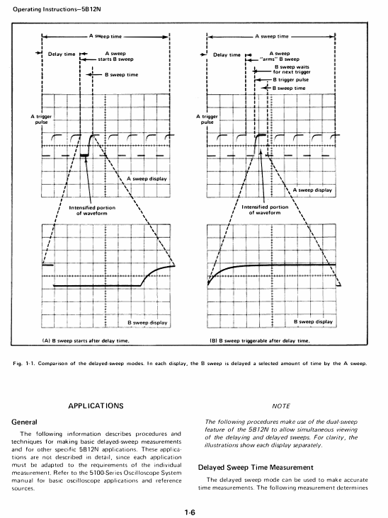
Dual time base generator: including A time base (main time base) and B time base (auxiliary time base), supporting three working modes (independent sweep, dual sweep, delayed sweep).
Scanning speed range:
A time base: 1 μ s/Div to 5s/Div (21 levels 1-2-5 sequence), 10x magnification (A SWP MAG) to reach 100ns/Div;
B time base: 0.2 μ s/Div to 0.5s/Div (20 levels 1-2-5 sequence), no amplification function.
Delay function: Set the delay time using the DELAY TIME MULT knob, with a range of 0.2-10.2 times the A time base sweep speed (corresponding to 1 μ s to 50s), for delayed sweep mode.
External signal support: External signals can be connected to replace the A time base display, and the amplifier mode provides two calibration deflection coefficients of 50mV/Div and 0.5V/Div.
2. Key panel controls (function summary)
Control Category Control Name Function Description
Mode control MODE (A/B/dual sweep) - A: Only A time base works, B time base is locked
-B: Only B time base works, A time base is locked
-Dual sweep frequency (A+B pressed): A and B time bases work simultaneously, with time sharing display
A INTEN-B DLY'D Delay Sweep Mode Switch, to be coordinated with A/B buttons:
-Only press A: display A time base, B time base works synchronously (strengthened segment display)
-Only press B: B time base delay start (delay time is determined by A time base and DELAY TIME MULT)
-Press A+B: A time base strengthening segment and B time base delay display
B TRIG AFTER DLY is triggered after a delay in the B time base. It is necessary to first meet the delay time set by the A time base, and then activate the B time base with the trigger signal
Time base control A/B Seconds/DIV selects calibration scanning speed, and the knob skirt lights up to display the current gear (A is a dark gray knob, B is a light gray knob)
A SWP MAG A time base is amplified 10 times, and the scanning speed is directly displayed after amplification (such as 1 μ s/Div → 100ns/Div), with only the central grid area visible
DELAY TIME MULT delay multiple adjustment, range 0.2-10.2 times A time base sweep speed, used to locate the starting point of delayed sweep frequency
A SINGL SWP A Time Base Single Sweep Mode, only triggered once when pressed, requires A RESET reset
A RESET resets the sweep circuit: re standby in single mode, terminate the current sweep in any mode
Trigger Control A/B TRIGGERING Source - LEFT/RIGHT: Select the left/right vertical plugin as the trigger source
-COMPOSITE (exclusive to A): Select the display signal as the trigger source (press A+B)
-LINE: Select the power frequency (50/60Hz) as the trigger source
-EXT (unique to A): Select A EXT INPUT external signal as the trigger source
A/B TRIGGERING COUPLING - AC (pressed): Capacitive coupling, blocking DC, attenuating low frequencies<50Hz
-DC (pop-up): Direct coupling, retaining DC and low-frequency components
A/B TRIGGERING SLOPE -+SLOPE (pressed): Positive slope trigger (signal rising edge starts sweep frequency)
-- SLOPE (pop-up): Negative slope trigger (signal falling edge initiates frequency sweep)
A/B TRIGGERING LEVEL adjusts the trigger level, and the ± region corresponds to the positive and negative voltage points of the signal. Rotate clockwise to increase the trigger level
Status and display READY INDICATOR indicator light, illuminated in A time base single mode to indicate readiness (trigger acceptable)
Display (ALT/CHOP) - ALT (pop-up): alternately displays A/B time base, suitable for fast scanning speed
-CHOP (pressed): Chopper displays A/B time base, suitable for scenarios with slow scanning speed or large scanning speed differences
INTEN BAL balances the brightness of A and B time base trajectories for clear observation or photography in dual sweep mode
Working mode and operation process
1. Three core working modes
Mode name trigger condition applicable scenario key operation steps
Independent sweep mode (A or B works separately) - Normal trigger (AUTO TRIG pops up): The trigger signal must be ≥ 15Hz and the LEVEL must be correct
-Automatic trigger (AUTO TRIG pressed): Free operation at<15Hz or no trigger (baseline illuminated)
-Single trigger (A SINGL SWP pressed): Only 1 sweep frequency, A RESET is required to reset the regular time measurement of simple signals, non repetitive signal photography 1. Press the A or B button of MODE
2. Choose TRIGGERING SOURCE-COUPLING/SLOPE
3. Adjust LEVEL to stable display, press A RESET for standby in single mode
Dual sweep mode (A+B working simultaneously) A trigger source corresponds to the left vertical plugin, B trigger source corresponds to the right vertical plugin, and trigger parameters need to be set separately to observe two signals (or different scan speeds of the same signal) simultaneously. 1. Press the A+B button of MODE
2. Set the PLAY to ALT (fast scanning speed) or CHOP (slow scanning speed)
3. Adjust the Seconds/DIV and trigger parameters of A/B separately, and use INTERN BAL to balance the brightness
Delay sweep mode (B time base delay start): After triggering A time base, start B time base (or wait for triggering after B time base delay) signal local amplification, time difference measurement, pulse jitter measurement. 1. Press the A INTEN-B DLY'D button of MODE (in conjunction with A/B)
2. Set A Seconds/DIV (delay benchmark) and DELAY TIME MULT (delay multiplier)
3. Adjust the B Seconds/DIV (delayed sweep speed) to be faster than the A time base to avoid logic errors
2. Sweep frequency amplification operation (taking 100x amplification as an example)
Preparation for dual sweep mode: Press the A+B button, connect the left/right vertical plugs to the same signal, set A Seconds/DIV to 0.1ms/Div (display complete waveform);
Delay mode start: Press A INTEN-B DLY'D and use DELAY TIME MULT to locate the enhanced segment to the pulse that needs to be amplified;
B time base setting: B Seconds/DIV is set to 1 μ s/Div (1/100 of A scan speed), and at this time B time base displays a 100x amplified waveform of A time base enhancement segment;
Calculate magnification factor:
Magnification factor=B Seconds/DIV settings
A Seconds/DIV setting= 1×10 −60.1×10 −3=100
Application scenarios and examples
1. Time difference measurement (interval between two pulses)
Signal access: The left/right vertical plug-in is connected to a signal containing two pulses, in dual sweep mode (A+B pressed), with Volts/Div set to 2 grid amplitudes;
A Time Base Setting: A Seconds/DIV is set to 0.2m/Div (displaying the multi grid distance between two pulses), and the trigger parameter is adjusted to stable display (using CHOP mode for slow scanning speed);
Delay mode start: Press A INTEN-B DLY'D, set B Seconds/DIV to 2 μ s/Div (1/100 of A scan speed), and strengthen the segment length by about 0.1 grid;
Delay positioning: DELAY TIME MULT first locates the rising edge of the first pulse (reading 1.31), and then locates the second pulse (reading 8.81);
Calculate time difference:
Time difference=(8.81-1.31) × 0.2ms=1.5ms
.
2. Pulse jitter measurement
Signal access: Left/right vertical plug-in access pulse signal, dual sweep frequency mode, Volts/Div set to 4 grid amplitude;
A Time Base Setting: A Seconds/DIV is set to display the complete waveform, and the trigger parameters are adjusted to stability;
Delay mode start: Press A INTEN-B DLY'D, DELAY TIME MULT locate the pulse to be tested, and set B Seconds/DIV to 0.2 μ s/Div (covering the pulse front);
Jitter calculation: observe the horizontal offset of the pulse in the B time base (example 0.5 grid),
Jitter=0.5 × 0.2 μ s=0.1 μ s
Electrical characteristics (core parameters)
Specific parameter accuracy/range for characteristic category
A time base scanning speed calibration range: 1 μ s/Div-5s/Div (21 levels); 100ns/Div 1 μ s/Div-1s/Div after 10x magnification: ± 3%; 2s/Div-5s/Div:±4%; Enlarged+1%
Non calibrated range: continuously adjustable, extending up to 12.5/s Div-
B time base scanning speed calibration range: 0.2 μ s/Div-0.5s/Div (20 levels) 1 μ s/Div-0.1s/Div: ± 3%; 0.2 μ s/Div, 0.5 μ s/Div, 0.2 s/Div, 0.5 s/Div: ± 4%
Delay characteristics: Delay multiple: 0.2-10.2 times A time base scanning speed (1 μ s-50s) 1 μ s/Div-0.5s/Div: ± 1%; 1s/Div-5s/Div:±2%
Inherent latency: ≤ 500ns-
Delay jitter: ≤ 1/20000 × 10x A time base scanning speed-
Trigger characteristic internal trigger (DC coupling): ≥ 0.4 grid (DC-1MHz); ≥ 0.6 grid (2MHz)-
External trigger (A time base): ≥ 200mV (DC-2MHz) Input RC: 1M Ω± 2%//70pF
Maximum safe input voltage: 350V (DC+peak AC)-
Amplifier mode deflection coefficient: 50mV/Div, 0.5V/Div ± 3%
Bandwidth: DC - ≥ 1MHz (AC coupling 50Hz - ≥ 1MHz)-
Non calibration range: ≥ 10:1 attenuation-
- YOKOGAWA
- Reliance
- ADVANCED
- SEW
- ProSoft
- WATLOW
- Kongsberg
- FANUC
- VSD
- DCS
- PLC
- man-machine
- Covid-19
- Energy and Gender
- Energy Access
- Renewable Integration
- Energy Subsidies
- Energy and Water
- Net zero emission
- Energy Security
- Critical Minerals
- A-B
- petroleum
- Mine scale
- Sewage treatment
- cement
- architecture
- Industrial information
- New energy
- Automobile market
- electricity
- Construction site
- HIMA
- ABB
- Rockwell
- Schneider Modicon
- Siemens
- xYCOM
- Yaskawa
- Woodward
- BOSCH Rexroth
- MOOG
- General Electric
- American NI
- Rolls-Royce
- CTI
- Honeywell
- EMERSON
- MAN
- GE
- TRICONEX
- Control Wave
- ALSTOM
- AMAT
- STUDER
- KONGSBERG
- MOTOROLA
- DANAHER MOTION
- Bentley
- Galil
- EATON
- MOLEX
- Triconex
- DEIF
- B&W
- ZYGO
- Aerotech
- DANFOSS
- KOLLMORGEN
- Beijer
- Endress+Hauser
- schneider
- Foxboro
- KB
- REXROTH
- YAMAHA
- Johnson
- Westinghouse
- WAGO
- TOSHIBA
- TEKTRONIX
- BENDER
- BMCM
- SMC
- HITACHI
- HIRSCHMANN
- XP POWER
- Baldor
- Meggitt
- SHINKAWA
- Other Brands
- UniOP
- KUKA
- IBA
- Beckhoff
-
ADLINK CPCI-6860A - 51-31310-OB10 industrial motherboard CompactPCI SBC
-
ADLINK AmITX-SL-G-H110 - 51-7A104-0A30 Mini-ITX Industrial Motherboard
-
ADLINK PXI-2005-003 - CPCI Industrial PC Data Acquisition Card Multi-Function DAQ
-
ADLINK DININ-814M - 51-14032-0A3D SCSI-100P cable connection Interface Terminal Board
-
ADLINK CPCI-3920NA/C2D15/M1G - 3U CompactPCI Intel Core 2 Duo Single Board Computer
-
ADLINK PCIE-8560 - 51-18014-0A20 Communication Card High Speed DAQ
-
ADLINK PCI-C154+ - Motion Control Card 4-axis Motion Controller Board
-
ADLINK PCI-RTV24 - image capture card Analog Video Frame Grabber
-
ADLINK NuPRO-842LV/P - 51-41360-0B30 Industrial Motherboard CPU Board
-
ADLINK cBP-3208/3208R - CPCI Board 3U 8-Slot CompactPCI Backplane
-
ADLINK PCI-8164 - 4-Axis Motion Controller PCI Card 51-12406-0A40
-
ADLINK PCIe-GIE64+ - 4-CH GigE Vision PoE+ Frame Grabber Video Capture Card
-
ADLINK CPCI-6860 / 6860A - CompactPCI Dual Xeon Single Board Computer
-
ADLINK IEC-915GV - REV 1.1 Industrial motherboard CPU Board
-
ADLINK ND-6520 - Technology RS-232 to RS-422RS-485 Converter NuDAM Module
-
ADLINK RTV-24 / PCI-MP4S - 51-12519-1C30 4-Channel Real Time Video Capture Board
-
ADLINK cPCI-6910 / cPCI-6910AM/M1G - cPCI-6910AM/DXL16/M1G/S80G(G)-3120 BOARD CompactPCI SBC
-
ADLINK NUPRO-A40H - Linghua 51-41807-1A30 Industrial Control Computer Motherboard
-
ADLINK USB-3488A - USB to GPIB INTERFACE USB-3488A(G) Controller Module
-
ADLINK PCI-8134A - motion control card 4-Axis Controller Card
-
ADLINK PCI-7432 - Board 32-Channel input / 32-output Isolated Digital I/O PCI Card
-
ADLINK PCI-8134A - 51-12421-0A10 motion controller card tested
-
ADLINK LPCIe-7230 - 32 CH Isolated Input/output Card 2 Interrupts Low Profile PCIe
-
ADLINK NuPRO-E340 - industrial computer motherboard 51-47807-0A30 PICMG 1.3 SHB
-
ADLINK PCI-7434 - High-speed Digital Acquisition Card 64-CH Isolated DO Card
-
ADLINK NuPRO-E330 - 51-41805-0A20 Indsutrial Board SHB Single Board Computer
-
ADLINK PCI-7248 - OPTO-22 48 CHANNEL DIO DIGITAL TTL/DTL I/O 51-12006-0A40 GP
-
ADLINK PCI-8134 - Motion control card 4-Axis Controller Card
-
ADLINK AMP-208C - Movimiento Control Tarjeta 51-12420-1A20 W/Expansión & Breakout
-
ADLINK PCI-8164 - 51-12406-0A40 PCB Board 4-Axis Motion Controller Card
-
ADLINK DIN-68Y-SGII / DIN-68M-J3A - Terminal Board Connector Interface Block
-
ADLINK PCIe-7432 - Technology 51-18402-0A10 PCIe Card With High Input Range
-
ADLINK PCI-8144 / PCI-8144N - Motion control card 4-Axis Stepper Controller Card
-
ADLINK HSL-HUB3/REPEATER - HIGH SPEED LINK EXTENSION MODULES Distributed Hub Module
-
ADLINK ND-6017 - Data Logging + Acquisition 8CH A/D input Mod NuDAM Module
-
ADLINK LPCIe-7250 - data acquisition card Low Profile 8-CH Relay Output Card
-
ADLINK PCI-7432 - I/O card 64-CH Isolated Digital Input Output PCI Card
-
ADLINK IMB-M43H - industrial control computer motherboard Q87 Chip Micro-ATX
-
ADLINK MP-C154 - Motion control Card 4-Axis Motion Controller Board
-
ADLINK PCI-RTV24 - image capture card Video Frame Grabber Card
-
ADLINK PCI-7250 - 8-CH Relay Output & 8-CH Isolated DI Card
-
ADLINK PCI-6308V - 8-CH 12-Bit Isolated Analog Output PCI Card PCB-I-E-1148=6EX2
-
ADLINK PCI-7248 - capture card 48-CH Opto-22 Compatible DIO Card
-
ADLINK HSL-AI16A02-M-VV - Analog Input Output Distributed Module
-
ADLINK NuPRO-A301 - Rev:1.4 NUPRO-A301 PICMG Full-Size Single Board Computer
-
ADLINK PCI-6208V-GL - 8-CH Voltage Analog Output PCI Card
-
ADLINK PCI-8134A - 51-12421-0A10 4-Axis Motion Controller Card
-
ADLINK MNET-S23 - TECHNOLOGY MNET S23 - SERVO DRIVER CONTROL MODULE
-
ADLINK M-342 - ATX I3 I5 I7 Q67 Industrial Motherboard
-
ADLINK NUPRO-780 - Industrial Motherboard CPU Board PICMG SBC
-
ADLINK MP-C154 / MP-C152 - 4-Axis Motion Control Card Pulse-Train Controller
-
ADLINK NuPRO-935A/LV10B0 - Motherboard 51-41802-0A10 GP w/RAM Industrial Control Board
-
ADLINK MP-C154 - Motion control card 4-Axis Motion Controller Mainboard
-
ADLINK PCI-7250 - PCI Acquisition Card 8-CH Relay Output Isolated DI Card
-
ADLINK ACL-7124 - Technology Inc.24 DIO Card Digital Input Output Card
-
ADLINK PCI-8554 A2 - Timer/Counter Data Acquisition Card
-
ADLINK DIN-825-GP4 - Terminal Block Interface Board Breakout Module
-
ADLINK NuPR0-761 - REV:1.1 Industrial motherboard Full-Size PICMG SBC
-
ADLINK MXE-1401/M8G (G) - Matrix Fanless Embedded Computer Industrial PC
-
ADLINK HSL-DI16DO16-UD-NN - Digital 16 Channel I/O Mod Distributed I/O Module
-
ADLINK ND6520 - NUDAM INTELLIGENT DA&C MODULE RS232-RS-422/RS485 CONVERTOR
-
ADLINK NUPRO-761 - REV:1.1 Industrial Motherboard CPU Board
-
ADLINK AMP-208C - Motion Control Card 51-12420-1A20 DSP-based 8-axis
-
ADLINK NuPRO-A301REV 1.4 - with packaging industrial computer motherboard PICMG SBC
-
ADLINK PCM-9112+ - 51-12300-0A2 industrial motherboard Multi-Function DAQ PC/104 Module
-
ADLINK PCM-7250+ - 8-CH Relay Outputs & 8-CH Isolated DI Module PC/104
-
ADLINK PCI-RTV24 - Image capture card Analog Video Frame Grabber
-
ADLINK PCI-8134 - Motion Controller PCI Card 4-Axis Controller Board
-
ADLINK PCI-7432 - Isolated Digital I/O PCI Card
-
ADLINK PCI-8554 A2 - acquisition card Timer/Counter Card
-
ADLINK PCI-8132 - Rev.A2 2-Axis Servo & Stepper Motion Controller Card
-
ADLINK PCI-8132 - Data Acquisition card 2-Axis Motion Controller Card
-
ADLINK EBP-13E4 - 51-46703-0A30 Industrial Backplane Board Passive Backplane
-
ADLINK PCI-800L - Electronic Card Interface Controller Card
-
ADLINK PCIe-GIE72 - 51-18531-0A10 PCB Board GigE Vision Frame Grabber
-
ADLINK DAQ-2010(G)-OOBO - Simultaneous-Sampling Multi-Function DAQ Card
-
ADLINK PCI-9112 - REV.B1 Multifunction DAQ Card Data Acquisition Card
-
ADLINK PCI-7230 - 51-12003-DA60 32-CH Isolated Digital I/O Card
-
ADLINK PCI-7432 - Data Acquisition Card Isolated Digital I/O PCI Card
-
ADLINK ETX-AT-N270-18/LXE - 51-71111-0A20 ETX CPU Module Motherboard
-
ADLINK HSL-DI32-UD-N - DIGITAL INPUT 32 POINTS MODULE Distributed I/O
-
ADLINK AMP-204C - Motion Control card DSP-Based 4-Axis Advanced Controller
-
ADLINK MNET-4XMOG-0050 - Four-axis Motion Controller Distributed Motion Module
-
ADLINK AMP-204C - Motion control card DSP-Based 4-Axis Pulse-Train Controller
-
ADLINK PCI-7442 - Switch card 64-Channel Datalogging & Acquisition Card
-
ADLINK M-302 - Industrial control motherboard ATX PC Board
-
ADLINK NUPRO-852 / NUPRO-852LV - Industrial motherboard Single Board Computer
-
ADLINK PCI-8134 - REV.B1. 4-Axis Motion Controller Card
-
ADLINK PCI-GIE62 + - 51-18502-0A20 2-CH GigE Vision Frame Grabber PoE Card
-
ADLINK PCI-MPG24 - 51-12523-0B20 MPEG4 Card Video Compression Hardware
-
ADLINK HSL-TB32-M-DIN - 32-CH I/O TERMINAL W/ HSL-AI16AO2-M-VV MODULE
-
ADLINK PCI-M114-GL - PCB Ver 2.1 Motion Controller Axis Card
-
ADLINK IMB-M40H - SYM76996H61 motherboard Industrial Computer Mainboard
-
ADLINK NUPRO-A40H - 51-41807-1A20 industrial control motherboard H61 Chip
-
ADLINK PCI-M114-GL - Axis Card Data Acquisition Card PCB VER2.2 Motion Controller
-
ADLINK PCI-8134 - Motion Controller PCI Card 4-Axis Controller Board
-
ADLINK PCI-8102 - Motion control card 2-Axis Servo & Stepper Controller
-
ADLINK NuPRO-841REV:3.0 - motherboard Industrial Control PC Board
-
ADLINK HSL-TB32-U-DIN REV A1 - Breakout Terminal Board Field I/O Module
-
ADLINK AMP-204C - Motion Control card DSP-Based 4-Axis Pulse-Train Controller
-
ADLINK NUPRO-A40H - 51-41807-1A20 industrial control motherboard H61 PC Board
-
ADLINK PCI-6308A / PCI-6308V - 51-12202-0A50 Isolated Analog Output Card
-
ADLINK AMP-204C - DSP-Based 4-Axis Advanced Pulse-Train Motion Controller
-
ADLINK PCI-7434 - Technology 64-Channel Isolated Digital I/O PCI Cards
-
ADLINK CPCI-6840 / CPCI-6840V / PM16/M1G-12G0 - CompactPCI Single Board Computer CPU Module
-
ADLINK PCIE-GIE74 - Motherboard Video Capture Card 51-18531-0A10 Frame Grabber
-
ADLINK NuPRO-E330 - industrial computer equipment motherboard Control Mainboard
-
ADLINK AMP-208C / 51-12420-1A20 - Motion Control Card W/ Expansion & Breakout Board
-
ADLINK HPCI-14S12U - industrial computer baseboard Passive Backplane 14 Slots
-
ADLINK PCI-8164 - 4-Axis Motion Controller PCI Card W/ 1x Cable, 1x Breakout Box
-
ADLINK PCIe-RTV24 - 51-18016-0A20 Image Acquisition Video Capture Card
-
ADLINK M-342 - 5 PCI ATX Motherboard Industrial PC Mainboard
-
ADLINK PCI-FIW64 - 4/2 Channel IEEE1394B Image Capture Card FireWire Frame Grabber
-
ADLINK PCI-7432 - digital IO card 64-CH Isolated Digital Input Output Card
-
ADLINK 51-12001-0C20 - Circuit Board PCI-7200 Data Acquisition Controller Card
-
ADLINK PXI-3920 - PXI 3U cPCI Industrial Controller Embedded System CPU Board
-
ADLINK NuPRO-841REV:2.0 - motherboard Industrial Control PC Board
-
ADLINK NuPro-E330 - 51-41805-0A20 PCB Industrial Control Computer Motherboard
-
ADLINK PCI-RTV24 - Image capture card Analog Video Frame Grabber
-
ADLINK PCI-7442 - Switch card 64-Channel Datalogging & Acquisition Card
-
ADLINK HPX-13S4 - device baseboard Passive Backplane Riser Card
-
ADLINK PCI-9112 REV A.1 - Multi Function DA&C Board Data Acquisition Card
-
ADLINK PCI-7248 - 51-12006-0A40 Card Control 48-CH Digital I/O Module
-
ADLINK CPCI-6860 / 6860A - motherboard CompactPCI Dual Xeon Single Board Computer
-
ADLINK DPAC-3020-11(G) - Embedded PC Automation Controller Machine Control Board
-
ADLINK NuPRO-841 REV:1.0 - industrial control motherboard CPU Board
-
ADLINK MNET-4XMOG-0050 - Four-axis Motion Controller MNET Motion Control Card
-
ADLINK ETX-AT-N270-18/LXE - 51-71111-0A20 ETX CPU Module Motherboard

K-JIANG

Add: Jimei North Road, Jimei District, Xiamen, Fujian, China
Tell:+86-15305925923