
K-WANG


Tektronix 5440 oscilloscope
Tektronix 5440 oscilloscope
Overview of Instrument Core
(1) Hardware structure
Plugin compartment: There are a total of 3 compartments that can accommodate 5000 series plugins (without N suffix plugins supporting display readings), 2 vertical compartments (left and middle) for amplifier plugins, and 1 horizontal compartment (right) for time base plugins. The combination of plugins determines the functionality of the measurement system.
Key controls:
Display related: INTENSITY adjusts the brightness of the trajectory, READOUT INTENS only adjusts the brightness of the reading part (the reading system fails when counterclockwise to the bottom), FOCUS controls for clear display, and BEAM FINDER compresses the trajectory to the scale range.
Power supply and calibration: The power switch (POWER) controls the power on/off, and the internal calibrator (CALIBRATOR LOOP) provides a square wave signal with a voltage of 400mV (± 1%) and a current of 4mA (± 1%), with a frequency of twice the power supply frequency, for calibration and probe compensation.
External interface: EXT INTENSITY INPUT interface receives Z-axis modulation signals (DC coupling,+5V enhanced brightness, -5V reduced brightness, maximum safe input ± 50V, frequency range DC to 2MHz).
(2) Core functions
Display mode:
Alternate mode: The time base plugin display switch pops up and switches between the activated plugin/channel with each CRT scan, suitable for high-frequency signals.
Chop mode: When the time base plugin display switch is pressed, it electronically switches between channels at a rate of 100kHz, suitable for displaying low-frequency signals or single event phenomena.
X-Y operation: Install 5A series amplifiers or 5B series time base plugins with amplifier channels in the horizontal cabin to receive X signals, and 5A series amplifiers in the vertical cabin to receive Y signals, achieving signal comparison display.
Grating display: Both the left vertical cabin and the horizontal cabin are equipped with 5B series time base plugins. The scanning speed of the vertical cabin is slower than that of the horizontal cabin, and brightness modulation is achieved through EXT INTENSITY INPUT, which can simulate TV display.
Reading System: Only supports 5400 series plugins, displaying alphanumeric information in real-time with analog waveforms on CRT. Each plugin's reading occupies a fixed position (channel 1 is indexed at the top, channel 2 is indexed at the bottom), displaying up to 6 readings (option 3 can select 8 readings). The reading interruption waveform display is only about 20 microseconds/character.

Operation Guide
(1) First operation process (19 steps in total, with the following key steps)
Plug in preparation: Install 5A series amplifier plugs in the left/middle vertical cabin and 5B series time base plugs in the horizontal cabin.
Power connection: After confirming the operating voltage, turn off the power switch and connect a power source that meets the voltage/frequency requirements.
Initial setup:
Amplifier plugin: Display on, center position, CH1 Volts/Div set as needed, CH1 Variable Volts/Div clockwise to the end (Cal), CH1 Input Coupling set to DC, mode set to CH1.
Time base plugin: Display alternately (button pops up), center position, Main Sec/Div set to 5ms, Variable Seconds/Div clockwise to the end (Cal), Swp Mag turned off (button pops up), Main Trig Level counterclockwise to the end, trigger source selected to the left (or center, if the amplifier is in the middle compartment), coupled with Auto Trig, AC Couple,+Slope, mode set to Main Sweep.
Calibration check: Connect the probe/test line to the calibrator, adjust the trigger level to obtain stable display, check the waveform amplitude (4 divisions) and cycle (6 complete cycles, 5 cycles for 50Hz power supply), and recalibrate if abnormal.
(2) Basic measurement methods
Calculation formula/explanation for key steps of measurement type
AC peak to peak voltage: 1. The vertical plug-in input coupling is set to Gnd, and AC is set after receiving the signal; 2. Volts/Div is set to display 5-6 vertical divisions, and Variable Volts/Div is set to Cal; 3. Adjust the trigger to obtain stable display, and measure the vertical division of peak values; 4. Result=Division value × Volts/Div × Probe attenuation ratio (if any) Example: 4.6 Division value × 5V/Div=23V
DC instantaneous voltage: 1. The vertical plug-in input coupling is set to Gnd, and the trajectory is positioned to the reference line (such as the bottom part degree, negative voltage is used at the top); 2. After receiving the signal, set the DC and measure the vertical division between the reference line and the measurement point; 3. Result=division value x Volts/Div x probe attenuation ratio (if any), polarity determined by waveform position (+input and waveform is positive on the reference line) Example: 4.6 division x 2V/Div=+9.2V
Time cycle 1. Connect the signal, select AC/DC coupling, set Volts/Div to display 4 divisions; 2. Adjust the trigger to obtain stable display, set Sec/Div to 1 cycle display<8 divisions; 3. Measure the horizontal division of two points (Variable Sec/Div at Cal); 4. Result=Division value x Sec/Div Example: 5 divisions x 0.1ms/Div=0.5ms
Frequency 1. Obtain the period (T) by measuring the time period method; 2. Frequency=1/T Example: Period 0.5ms, Frequency=1/0.5ms=2kHz
Rising time (10% -90% point) 1. Connect the signal, set Volts/Div and Variable to display 5 vertical divisions; 2. Adjust the trigger to obtain stable display, set Sec/Div to 10% -90% point display<8 divisions; 3. Measure the horizontal division of two points; 4. Result=Division value x Sec/Div Example: 4 divisions x 1 μ s/Div=4 μ s
Specification parameters
1: Vertical amplifier specifications
Additional information on characteristic performance requirements
Bandwidth (6-degree reference) DC to at least 85MHz (067-0680-00 calibration fixture); DC to at least 50MHz (calibrated 5A48)-
Rise time (6 divisions reference) 7ns or less (calibrated 5A48)-
Distortion (6-degree reference) 5% or less (067-0680-00 calibration fixture); 4% or less (calibrated 5A48)-
The influence of position on distortion ± step response signal deviation does not exceed ± 5% (trajectory deviation from the center of the scale does not exceed 1 division)-
Within ± 0.5 divisions of the center of the vertical center scale-
Delay line length 140ns-
Chopping rate 50kHz (+50% -30%), conducting in 3 μ s and turning off in 2 μ s-
Alternating rate: scan every two times-
Table 2: Specifications of Horizontal Amplifier and Z-axis Amplifier
Performance requirements for amplifier type characteristics
Horizontal amplifier bandwidth DC to at least 2MHz (8-division signal reference); At least 20kHz at the low frequency end
The Z-axis amplifier inputs a voltage of+5V to switch the CRT beam from off to on; -5V switches the beam from on to off
Available frequency range DC to 2MHz
Input impedance (resistance) 10k Ω
Table 3: Power, Environment, and Physical Specifications
Category Characteristics Performance Requirements
Power input voltage (RMS) nominal 100V, 110V, 120V, 200V
Input frequency adapted to standard power frequency
Maximum 100W at 120V AC and 60Hz input power
Fuse 120V AC with 1.25A slow melting; 240V AC with 0.7A slow melting
Environmental working temperature: 0 ° C to+50 ° C
Storage temperature -40 ° C to+70 ° C
Working altitude up to 15000 feet
Storage altitude up to 50000 feet
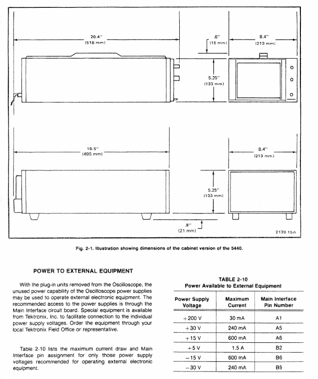
Physical weight 25lbs (11kg)
Panel and shell anodized aluminum panel (gray vinyl coated frame), blue vinyl coated shell
Scale dial 8 × 10 divisions, 1.22cm/division, standard white internal scale line, optional black
Installation and maintenance
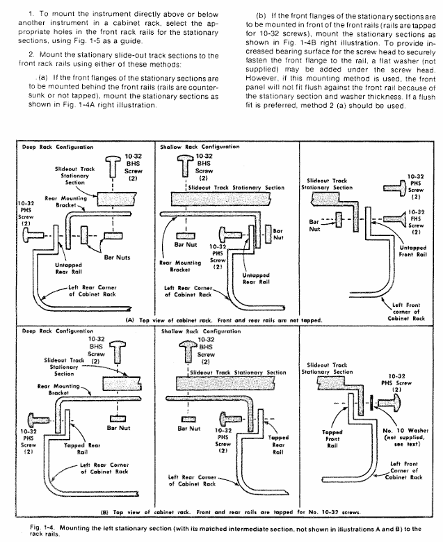
(1) Rack installation
Requirement: Suitable for 19 inch standard racks (Universal, EIA, RETMA, Western Electric hole positions), with a minimum vertical space of 5-1/4 inches and an additional 1/4 inch heat dissipation space above and below; Front rail spacing ≥ 17-5/8 inches (unthreaded) or 17-3/4 inches (tapped); The gap between the rear and the rack enclosure is ≥ 2 inches.
Sliding rail installation: The sliding rail is divided into left and right components (marked LH/RH), with the fixed section installed on the front and rear rails of the rack, the chassis section pre installed with instruments, and the middle section connecting the two; During installation, it is necessary to align horizontally to avoid exchanging left and right (which may cause the safety lock to fail and cause the instrument to slide). The front panel needs to be fixed with 10-32 screws (the rack needs to correspond to the hole position).
Maintenance: The slide rail does not require lubrication, and the dark coating on the sliding parts is permanently lubricated.
(2) Plugin installation and maintenance
Installation: Align the upper and lower slots of the plug-in with the cabin guide rail, and push it into the lock; It can be plugged and unplugged with power, without filling all cabins, only installing the required measuring plugs is needed.
Calibration: After the display unit is calibrated according to the instructions, the vertical/horizontal gain is standardized. The plug-in can be interchanged between cabins without the need for readjustment, but the basic calibration of the plug-in itself needs to be checked to ensure measurement accuracy (refer to the plug-in manual).
(3) Safety regulations
Maintenance safety: Only qualified personnel are allowed to carry out repairs, and individual repairs are prohibited (emergency personnel must be provided); Live maintenance should avoid touching exposed connections/components, and disconnect the power supply before dismantling panels, welding, or replacing components.
Power safety: The power supply must meet the RMS voltage between phase lines and between phase lines and ground ≤ 250V, and the grounding conductor of the power line must be reliably grounded.
Performance check
(1) Testing equipment requirements (key equipment as follows)
Equipment Name Performance Requirements Application Scenarios
DC voltmeter range 0-200V (accuracy 0.1%); 0-3000V (accuracy 1%) low/high voltage power supply inspection and adjustment
Calibration generator amplitude calibration 10mV-1V (accuracy ± 0.25%, 1M Ω load), square wave output gain inspection and adjustment
Timing generator outputs 5ns and 10ns markers (accuracy ± 1%) for scanning timing inspection (5ns, 10ns)
5A48 amplifier plug-in bandwidth DC to 500MHz, display mode CH1 vertical/horizontal system adjustment
5B42 time base plugin scanning speed of at least 10ns/div scanning timing inspection and adjustment
(2) Key inspection items
Trajectory alignment: Horizontal trajectories are aligned with the center horizontal scale line, and vertical trajectories are aligned with the center vertical scale line, with an error of ≤ 0.1 divisions.
Geometric shape: Trajectory curvature/inclination ≤ 0.1 divisions, angle between vertical and horizontal trajectories 90 °± 0.7 °.
Vertical performance:
Gain: Input 1kHz square wave, display 5V reference signal, vertical deflection of 5 divisions ± 0.15 divisions (± 3%).
Bandwidth: Input a 50kHz sine wave, display 6 divisions, increase the frequency until the amplitude drops to 4.2 divisions, and the frequency needs to be ≥ 50MHz (5A48 plugin).
Horizontal performance:
Gain: Input 1kHz square wave, display 5V reference signal, horizontal deviation of 5 divisions ± 0.15 divisions.
Bandwidth: Input a 50kHz sine wave, display 6 divisions, increase the frequency until the amplitude drops to 4.2 divisions, and the frequency needs to be ≥ 2MHz.
Reading system: In dual track mode, readings are displayed at the top/bottom of the CRT without overlap, corresponding to Volts/Div and Sec/Div settings; When CAL controls counterclockwise rotation, the ">" symbol is displayed on the left side of the reading.
- YOKOGAWA
- Reliance
- ADVANCED
- SEW
- ProSoft
- WATLOW
- Kongsberg
- FANUC
- VSD
- DCS
- PLC
- man-machine
- Covid-19
- Energy and Gender
- Energy Access
- Renewable Integration
- Energy Subsidies
- Energy and Water
- Net zero emission
- Energy Security
- Critical Minerals
- A-B
- petroleum
- Mine scale
- Sewage treatment
- cement
- architecture
- Industrial information
- New energy
- Automobile market
- electricity
- Construction site
- HIMA
- ABB
- Rockwell
- Schneider Modicon
- Siemens
- xYCOM
- Yaskawa
- Woodward
- BOSCH Rexroth
- MOOG
- General Electric
- American NI
- Rolls-Royce
- CTI
- Honeywell
- EMERSON
- MAN
- GE
- TRICONEX
- Control Wave
- ALSTOM
- AMAT
- STUDER
- KONGSBERG
- MOTOROLA
- DANAHER MOTION
- Bentley
- Galil
- EATON
- MOLEX
- Triconex
- DEIF
- B&W
- ZYGO
- Aerotech
- DANFOSS
- KOLLMORGEN
- Beijer
- Endress+Hauser
- schneider
- Foxboro
- KB
- REXROTH
- YAMAHA
- Johnson
- Westinghouse
- WAGO
- TOSHIBA
- TEKTRONIX
- BENDER
- BMCM
- SMC
- HITACHI
- HIRSCHMANN
- XP POWER
- Baldor
- Meggitt
- SHINKAWA
- Other Brands
- UniOP
- KUKA
- IBA
- Beckhoff
-
ADLINK CPCI-6860A - 51-31310-OB10 industrial motherboard CompactPCI SBC
-
ADLINK AmITX-SL-G-H110 - 51-7A104-0A30 Mini-ITX Industrial Motherboard
-
ADLINK PXI-2005-003 - CPCI Industrial PC Data Acquisition Card Multi-Function DAQ
-
ADLINK DININ-814M - 51-14032-0A3D SCSI-100P cable connection Interface Terminal Board
-
ADLINK CPCI-3920NA/C2D15/M1G - 3U CompactPCI Intel Core 2 Duo Single Board Computer
-
ADLINK PCIE-8560 - 51-18014-0A20 Communication Card High Speed DAQ
-
ADLINK PCI-C154+ - Motion Control Card 4-axis Motion Controller Board
-
ADLINK PCI-RTV24 - image capture card Analog Video Frame Grabber
-
ADLINK NuPRO-842LV/P - 51-41360-0B30 Industrial Motherboard CPU Board
-
ADLINK cBP-3208/3208R - CPCI Board 3U 8-Slot CompactPCI Backplane
-
ADLINK PCI-8164 - 4-Axis Motion Controller PCI Card 51-12406-0A40
-
ADLINK PCIe-GIE64+ - 4-CH GigE Vision PoE+ Frame Grabber Video Capture Card
-
ADLINK CPCI-6860 / 6860A - CompactPCI Dual Xeon Single Board Computer
-
ADLINK IEC-915GV - REV 1.1 Industrial motherboard CPU Board
-
ADLINK ND-6520 - Technology RS-232 to RS-422RS-485 Converter NuDAM Module
-
ADLINK RTV-24 / PCI-MP4S - 51-12519-1C30 4-Channel Real Time Video Capture Board
-
ADLINK cPCI-6910 / cPCI-6910AM/M1G - cPCI-6910AM/DXL16/M1G/S80G(G)-3120 BOARD CompactPCI SBC
-
ADLINK NUPRO-A40H - Linghua 51-41807-1A30 Industrial Control Computer Motherboard
-
ADLINK USB-3488A - USB to GPIB INTERFACE USB-3488A(G) Controller Module
-
ADLINK PCI-8134A - motion control card 4-Axis Controller Card
-
ADLINK PCI-7432 - Board 32-Channel input / 32-output Isolated Digital I/O PCI Card
-
ADLINK PCI-8134A - 51-12421-0A10 motion controller card tested
-
ADLINK LPCIe-7230 - 32 CH Isolated Input/output Card 2 Interrupts Low Profile PCIe
-
ADLINK NuPRO-E340 - industrial computer motherboard 51-47807-0A30 PICMG 1.3 SHB
-
ADLINK PCI-7434 - High-speed Digital Acquisition Card 64-CH Isolated DO Card
-
ADLINK NuPRO-E330 - 51-41805-0A20 Indsutrial Board SHB Single Board Computer
-
ADLINK PCI-7248 - OPTO-22 48 CHANNEL DIO DIGITAL TTL/DTL I/O 51-12006-0A40 GP
-
ADLINK PCI-8134 - Motion control card 4-Axis Controller Card
-
ADLINK AMP-208C - Movimiento Control Tarjeta 51-12420-1A20 W/Expansión & Breakout
-
ADLINK PCI-8164 - 51-12406-0A40 PCB Board 4-Axis Motion Controller Card
-
ADLINK DIN-68Y-SGII / DIN-68M-J3A - Terminal Board Connector Interface Block
-
ADLINK PCIe-7432 - Technology 51-18402-0A10 PCIe Card With High Input Range
-
ADLINK PCI-8144 / PCI-8144N - Motion control card 4-Axis Stepper Controller Card
-
ADLINK HSL-HUB3/REPEATER - HIGH SPEED LINK EXTENSION MODULES Distributed Hub Module
-
ADLINK ND-6017 - Data Logging + Acquisition 8CH A/D input Mod NuDAM Module
-
ADLINK LPCIe-7250 - data acquisition card Low Profile 8-CH Relay Output Card
-
ADLINK PCI-7432 - I/O card 64-CH Isolated Digital Input Output PCI Card
-
ADLINK IMB-M43H - industrial control computer motherboard Q87 Chip Micro-ATX
-
ADLINK MP-C154 - Motion control Card 4-Axis Motion Controller Board
-
ADLINK PCI-RTV24 - image capture card Video Frame Grabber Card
-
ADLINK PCI-7250 - 8-CH Relay Output & 8-CH Isolated DI Card
-
ADLINK PCI-6308V - 8-CH 12-Bit Isolated Analog Output PCI Card PCB-I-E-1148=6EX2
-
ADLINK PCI-7248 - capture card 48-CH Opto-22 Compatible DIO Card
-
ADLINK HSL-AI16A02-M-VV - Analog Input Output Distributed Module
-
ADLINK NuPRO-A301 - Rev:1.4 NUPRO-A301 PICMG Full-Size Single Board Computer
-
ADLINK PCI-6208V-GL - 8-CH Voltage Analog Output PCI Card
-
ADLINK PCI-8134A - 51-12421-0A10 4-Axis Motion Controller Card
-
ADLINK MNET-S23 - TECHNOLOGY MNET S23 - SERVO DRIVER CONTROL MODULE
-
ADLINK M-342 - ATX I3 I5 I7 Q67 Industrial Motherboard
-
ADLINK NUPRO-780 - Industrial Motherboard CPU Board PICMG SBC
-
ADLINK MP-C154 / MP-C152 - 4-Axis Motion Control Card Pulse-Train Controller
-
ADLINK NuPRO-935A/LV10B0 - Motherboard 51-41802-0A10 GP w/RAM Industrial Control Board
-
ADLINK MP-C154 - Motion control card 4-Axis Motion Controller Mainboard
-
ADLINK PCI-7250 - PCI Acquisition Card 8-CH Relay Output Isolated DI Card
-
ADLINK ACL-7124 - Technology Inc.24 DIO Card Digital Input Output Card
-
ADLINK PCI-8554 A2 - Timer/Counter Data Acquisition Card
-
ADLINK DIN-825-GP4 - Terminal Block Interface Board Breakout Module
-
ADLINK NuPR0-761 - REV:1.1 Industrial motherboard Full-Size PICMG SBC
-
ADLINK MXE-1401/M8G (G) - Matrix Fanless Embedded Computer Industrial PC
-
ADLINK HSL-DI16DO16-UD-NN - Digital 16 Channel I/O Mod Distributed I/O Module
-
ADLINK ND6520 - NUDAM INTELLIGENT DA&C MODULE RS232-RS-422/RS485 CONVERTOR
-
ADLINK NUPRO-761 - REV:1.1 Industrial Motherboard CPU Board
-
ADLINK AMP-208C - Motion Control Card 51-12420-1A20 DSP-based 8-axis
-
ADLINK NuPRO-A301REV 1.4 - with packaging industrial computer motherboard PICMG SBC
-
ADLINK PCM-9112+ - 51-12300-0A2 industrial motherboard Multi-Function DAQ PC/104 Module
-
ADLINK PCM-7250+ - 8-CH Relay Outputs & 8-CH Isolated DI Module PC/104
-
ADLINK PCI-RTV24 - Image capture card Analog Video Frame Grabber
-
ADLINK PCI-8134 - Motion Controller PCI Card 4-Axis Controller Board
-
ADLINK PCI-7432 - Isolated Digital I/O PCI Card
-
ADLINK PCI-8554 A2 - acquisition card Timer/Counter Card
-
ADLINK PCI-8132 - Rev.A2 2-Axis Servo & Stepper Motion Controller Card
-
ADLINK PCI-8132 - Data Acquisition card 2-Axis Motion Controller Card
-
ADLINK EBP-13E4 - 51-46703-0A30 Industrial Backplane Board Passive Backplane
-
ADLINK PCI-800L - Electronic Card Interface Controller Card
-
ADLINK PCIe-GIE72 - 51-18531-0A10 PCB Board GigE Vision Frame Grabber
-
ADLINK DAQ-2010(G)-OOBO - Simultaneous-Sampling Multi-Function DAQ Card
-
ADLINK PCI-9112 - REV.B1 Multifunction DAQ Card Data Acquisition Card
-
ADLINK PCI-7230 - 51-12003-DA60 32-CH Isolated Digital I/O Card
-
ADLINK PCI-7432 - Data Acquisition Card Isolated Digital I/O PCI Card
-
ADLINK ETX-AT-N270-18/LXE - 51-71111-0A20 ETX CPU Module Motherboard
-
ADLINK HSL-DI32-UD-N - DIGITAL INPUT 32 POINTS MODULE Distributed I/O
-
ADLINK AMP-204C - Motion Control card DSP-Based 4-Axis Advanced Controller
-
ADLINK MNET-4XMOG-0050 - Four-axis Motion Controller Distributed Motion Module
-
ADLINK AMP-204C - Motion control card DSP-Based 4-Axis Pulse-Train Controller
-
ADLINK PCI-7442 - Switch card 64-Channel Datalogging & Acquisition Card
-
ADLINK M-302 - Industrial control motherboard ATX PC Board
-
ADLINK NUPRO-852 / NUPRO-852LV - Industrial motherboard Single Board Computer
-
ADLINK PCI-8134 - REV.B1. 4-Axis Motion Controller Card
-
ADLINK PCI-GIE62 + - 51-18502-0A20 2-CH GigE Vision Frame Grabber PoE Card
-
ADLINK PCI-MPG24 - 51-12523-0B20 MPEG4 Card Video Compression Hardware
-
ADLINK HSL-TB32-M-DIN - 32-CH I/O TERMINAL W/ HSL-AI16AO2-M-VV MODULE
-
ADLINK PCI-M114-GL - PCB Ver 2.1 Motion Controller Axis Card
-
ADLINK IMB-M40H - SYM76996H61 motherboard Industrial Computer Mainboard
-
ADLINK NUPRO-A40H - 51-41807-1A20 industrial control motherboard H61 Chip
-
ADLINK PCI-M114-GL - Axis Card Data Acquisition Card PCB VER2.2 Motion Controller
-
ADLINK PCI-8134 - Motion Controller PCI Card 4-Axis Controller Board
-
ADLINK PCI-8102 - Motion control card 2-Axis Servo & Stepper Controller
-
ADLINK NuPRO-841REV:3.0 - motherboard Industrial Control PC Board
-
ADLINK HSL-TB32-U-DIN REV A1 - Breakout Terminal Board Field I/O Module
-
ADLINK AMP-204C - Motion Control card DSP-Based 4-Axis Pulse-Train Controller
-
ADLINK NUPRO-A40H - 51-41807-1A20 industrial control motherboard H61 PC Board
-
ADLINK PCI-6308A / PCI-6308V - 51-12202-0A50 Isolated Analog Output Card
-
ADLINK AMP-204C - DSP-Based 4-Axis Advanced Pulse-Train Motion Controller
-
ADLINK PCI-7434 - Technology 64-Channel Isolated Digital I/O PCI Cards
-
ADLINK CPCI-6840 / CPCI-6840V / PM16/M1G-12G0 - CompactPCI Single Board Computer CPU Module
-
ADLINK PCIE-GIE74 - Motherboard Video Capture Card 51-18531-0A10 Frame Grabber
-
ADLINK NuPRO-E330 - industrial computer equipment motherboard Control Mainboard
-
ADLINK AMP-208C / 51-12420-1A20 - Motion Control Card W/ Expansion & Breakout Board
-
ADLINK HPCI-14S12U - industrial computer baseboard Passive Backplane 14 Slots
-
ADLINK PCI-8164 - 4-Axis Motion Controller PCI Card W/ 1x Cable, 1x Breakout Box
-
ADLINK PCIe-RTV24 - 51-18016-0A20 Image Acquisition Video Capture Card
-
ADLINK M-342 - 5 PCI ATX Motherboard Industrial PC Mainboard
-
ADLINK PCI-FIW64 - 4/2 Channel IEEE1394B Image Capture Card FireWire Frame Grabber
-
ADLINK PCI-7432 - digital IO card 64-CH Isolated Digital Input Output Card
-
ADLINK 51-12001-0C20 - Circuit Board PCI-7200 Data Acquisition Controller Card
-
ADLINK PXI-3920 - PXI 3U cPCI Industrial Controller Embedded System CPU Board
-
ADLINK NuPRO-841REV:2.0 - motherboard Industrial Control PC Board
-
ADLINK NuPro-E330 - 51-41805-0A20 PCB Industrial Control Computer Motherboard
-
ADLINK PCI-RTV24 - Image capture card Analog Video Frame Grabber
-
ADLINK PCI-7442 - Switch card 64-Channel Datalogging & Acquisition Card
-
ADLINK HPX-13S4 - device baseboard Passive Backplane Riser Card
-
ADLINK PCI-9112 REV A.1 - Multi Function DA&C Board Data Acquisition Card
-
ADLINK PCI-7248 - 51-12006-0A40 Card Control 48-CH Digital I/O Module
-
ADLINK CPCI-6860 / 6860A - motherboard CompactPCI Dual Xeon Single Board Computer
-
ADLINK DPAC-3020-11(G) - Embedded PC Automation Controller Machine Control Board
-
ADLINK NuPRO-841 REV:1.0 - industrial control motherboard CPU Board
-
ADLINK MNET-4XMOG-0050 - Four-axis Motion Controller MNET Motion Control Card
-
ADLINK ETX-AT-N270-18/LXE - 51-71111-0A20 ETX CPU Module Motherboard

K-JIANG

Add: Jimei North Road, Jimei District, Xiamen, Fujian, China
Tell:+86-15305925923