
K-WANG


GE PACSystems RSTi EP EPSCPE100 Programmable Controller
GE PACSystems RSTi EP EPSCPE100 Programmable Controller
User characteristics
1 Controller Core Specifications
Main frequency: 1GHz
User memory: 1MB (configurable data and program memory, supports automatic positioning of symbolic variables)
I/O control capability: up to 2K I/O points
Reference table size:
Discrete quantity: 2k bits each for% I and% Q
Analog quantity: 2k words each for% AI and% AQ
Support batch memory (% W) for data exchange
Program blocks: Supports up to 512, with a maximum size of 128KB per block
Operating temperature range: -40 ° C to 70 ° C (-40 ° F to 158 ° F)
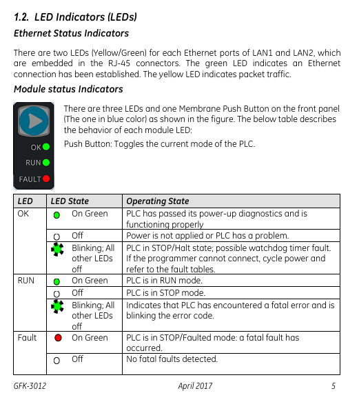
2 Operation and Instruction Components
Component Type Name Function Description
Short press the thin film run/stop button to switch CPU status (RUN/IO enabled) ↔ STOP/IO disabled); Default enabled, can be disabled in PME hardware configuration
LED indicator light OK (green) - always on: PLC diagnosed through power on and functions normally
-Extinguished: Not powered on or PLC malfunction
-Flashing (other LEDs off): PLC is in a stop/pause state, there may be a watchdog timer malfunction
LED indicator light RUN (green) - always on: PLC is in RUN mode
-Off: PLC is in STOP mode
-Flashing (other LEDs off): PLC encounters fatal error, flashing error code
LED indicator light FAULT (green) - always on: PLC is in stop/fault mode, fatal fault has occurred
-Extinguish: No fatal malfunction detected
Ethernet LED for each RJ-45 port (yellow/green) - Green: Ethernet connection established
-Yellow: There is packet transmission present
3 Ethernet Port Configuration
Number of port categories, functional characteristics, default network parameters
LAN1: 1 non switching, dedicated to high-speed Ethernet; Support communication with PME software via SRTP protocol IP: 192.168.0.100
Subnet mask: 255.255.255.0
Gateway: 0.0.0.0
LAN2 with 3 switch ports; Can be configured as an embedded Ethernet controller or PROFINET controller (supports simplex mode only) IP: 0.0.0.0
Subnet Mask: 0.0.0.0
Gateway: 0.0.0.0 (requires a valid IP configuration to be available)
4 Communication Capability
Server connection: Up to 16 SRTP+Modbus TCP combination connections (Modbus TCP not exceeding 8), or 16 SRTP connections, or 8 Modbus TCP connections
Client connections: up to 8, supporting SRTP, Modbus TCP, or a combination of both
EGD exchange: up to 8 simultaneous Type 1 Ethernet global data exchanges
Optimal performance combination: Server (Modbus/RTP) ≤ 4 channels, Client (Modbus/RTP) ≤ 4 channels, PROFINET nodes ≤ 8, EGD exchange ≤ 8
Hardware installation
1 Initial Inspection
Check if the shipping container is damaged. If damaged, immediately notify the carrier and keep the container as evidence
Record all serial numbers after unpacking (to be provided during warranty)
Check if the received components match the order, if not, contact customer service
Retain all packaging materials for future transportation
2 Installation location and method
2.1 Requirements for installation clearance
Left and right sides: minimum 50mm
Upper and lower sides: minimum 100mm (meets heat dissipation requirements)
2.2 DIN rail installation (default method)
Tilt the device so that the upper hook of the DIN rail adapter engages with the upper edge of the rail
Press the lower part of the device and hear a "click" sound, indicating that the lower hook is engaged with the lower edge of the guide rail (no additional tools required)
2.3 Panel installation (optional, requires adapter ICMFAACC001-AA)
Secure the panel mounting plate to the back of CPE100 using the 4 M3 screws provided with the adapter
Fix the protruding ears of the panel installation adapter in the corresponding position on the panel with 4 screws (size not exceeding M5)
Screw torque: When installing the adapter, it needs to be tightened to 5.3 in Ibs (0.6 Nm)
2.3 Grounding Requirements
Connect the grounding terminal of CPE100 to the DIN rail using 16-22 AWG braided wire (with terminal block)
DIN rails need to be grounded according to the instructions in the RSTi EP System Manual (GFK-2958)
Module startup
1 Required items for startup
PACSystems RSTi EP CPE100 Controller
Power supply: 9-30V DC, 5W output (must be a Class II power supply, labeled as "double insulated", "limited power supply (LPS)" or SELV power supply, and must have a minimum 32V DC and maximum 3A fuse)
Installation carrier: DIN rail (usually installed inside the cabinet) or optional panel mounting adapter (ICMFAACC001-AA)
Computer: Installed with Proficy Machine Edition (PME) software (version ≥ 9.50 SIM 1)
Ethernet cable: used to connect a computer to CPE100
Screwdriver: 1.4mm size (jeweler's specification, used for terminal operation)
2 Basic installation steps
Ensure that CPE100 is powered off
Choose DIN rail or panel installation method to fix CPE100
Connect power supply:
Wire specification: 22-16 AWG (copper wire, temperature rating 80 ° C)
Wiring length: not exceeding 30 meters
Screw torque: 2 in Ib
Connect Ethernet cable:
LAN1 port: connects computers for programming and protocols (SRTP, Modbus, EGD)
LAN1 port (if required): Connect to PROFINET network (there may be a typographical error in this document, combined with the previous text, it should be LAN2 port, subject to actual configuration)
Power on CPE100
Programming Configuration (EPSCPE100)
1 Basic Programming Requirements
Software version: PME 9.50 SIM 1 and above
Connection method: Connect the computer to CPE100 through LAN1 port, using the default IP address (192.168.0.100)
2 Project Creation and Conversion
New Project: Use the "RSTi-EP CPE100" Template
Existing project conversion: Convert other PLC projects to CPE100 projects through PME's "family conversion" function (constraints should be noted during conversion, such as the first PROFINET controller in the RX3i CPU320 application being assigned to the embedded PROFINET controller function of CPE100)
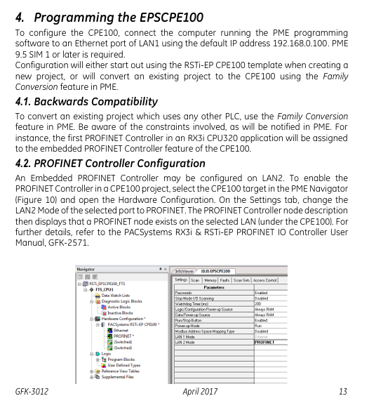
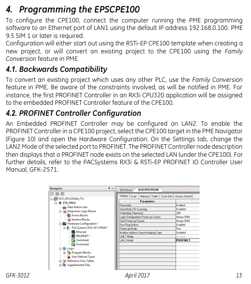
5.3 PROFINET Controller Configuration
Select the CPE100 target device in the PME navigator and open 'Hardware Configuration'
In the "Settings" tab, change the "Mode" of the LAN2 port to "PROFINET"
After configuration is complete, the PROFINET controller node description will display the existence of PROFINET nodes on the corresponding LAN (refer to the PACSystems RX3i&RSTi EP PROFINET IO Controller User Manual GFK-2571 for detailed operation)
Firmware upgrade process
1 Preconditions for Upgrade
Connection port: Use LAN1 port (default IP 192.168.0.100, can be modified through PME)
Controller status: Set to "stop disabled" mode (operated through programming software or run/stop switch)
PC settings: If using a proxy server, you need to modify the network settings to disable the proxy or automatically configure the proxy script
Firmware file: Download the latest PAC format firmware file from the GE support website (it is recommended to check for a new version before upgrading)
2 Upgrade Steps
Copy the firmware upgrade file (PAC format) to any directory on the computer
Open the browser and enter the programming communication IP of CPE100 (such as http://192.168.0.100 )Enter the homepage
Login: username "update", password "sierra" (both without quotation marks)
Click on 'Select File', find and select the copied PAC file, and then click 'Open'
Click on 'Upload File' and wait for the upload progress to complete (the upgrade process takes up to 4 minutes, during which power off is prohibited, otherwise the device may not be able to recover)
After the upgrade is completed, CPE100 will automatically reset, and the browser will display the "DONE" status to indicate success; If it fails, an error status will be displayed
After successful upgrade:
Close browser window
Mark the new firmware version on CPE100 (the label cannot cover the ventilation opening)
Restore CPE100 to 'Run Enable' mode through programming software
Product Restrictions (Release 1.0 Version)
Does not support MRP (Media Redundancy Protocol)
Not supporting C Toolkit
Cannot support timed interrupt blocks
RDSD is not supported
Troubleshooting
IP Address Reset and Device Recovery
Applicable scenarios: IP needs to be restored to default value (192.168.0.100), or the device is in an unknown state
Operation steps: When CPE100 is powered on, press and hold the "Run/Stop" button until the device is fully powered on (about 60 seconds)
Effect: IP address restored to 192.168.0.100, while clearing the contents of Flash and RAM
- YOKOGAWA
- Reliance
- ADVANCED
- SEW
- ProSoft
- WATLOW
- Kongsberg
- FANUC
- VSD
- DCS
- PLC
- man-machine
- Covid-19
- Energy and Gender
- Energy Access
- Renewable Integration
- Energy Subsidies
- Energy and Water
- Net zero emission
- Energy Security
- Critical Minerals
- A-B
- petroleum
- Mine scale
- Sewage treatment
- cement
- architecture
- Industrial information
- New energy
- Automobile market
- electricity
- Construction site
- HIMA
- ABB
- Rockwell
- Schneider Modicon
- Siemens
- xYCOM
- Yaskawa
- Woodward
- BOSCH Rexroth
- MOOG
- General Electric
- American NI
- Rolls-Royce
- CTI
- Honeywell
- EMERSON
- MAN
- GE
- TRICONEX
- Control Wave
- ALSTOM
- AMAT
- STUDER
- KONGSBERG
- MOTOROLA
- DANAHER MOTION
- Bentley
- Galil
- EATON
- MOLEX
- Triconex
- DEIF
- B&W
- ZYGO
- Aerotech
- DANFOSS
- KOLLMORGEN
- Beijer
- Endress+Hauser
- schneider
- Foxboro
- KB
- REXROTH
- YAMAHA
- Johnson
- Westinghouse
- WAGO
- TOSHIBA
- TEKTRONIX
- BENDER
- BMCM
- SMC
- HITACHI
- HIRSCHMANN
- XP POWER
- Baldor
- Meggitt
- SHINKAWA
- Other Brands
- UniOP
- KUKA
- IBA
- Beckhoff
-
ADLINK CPCI-6860A - 51-31310-OB10 industrial motherboard CompactPCI SBC
-
ADLINK AmITX-SL-G-H110 - 51-7A104-0A30 Mini-ITX Industrial Motherboard
-
ADLINK PXI-2005-003 - CPCI Industrial PC Data Acquisition Card Multi-Function DAQ
-
ADLINK DININ-814M - 51-14032-0A3D SCSI-100P cable connection Interface Terminal Board
-
ADLINK CPCI-3920NA/C2D15/M1G - 3U CompactPCI Intel Core 2 Duo Single Board Computer
-
ADLINK PCIE-8560 - 51-18014-0A20 Communication Card High Speed DAQ
-
ADLINK PCI-C154+ - Motion Control Card 4-axis Motion Controller Board
-
ADLINK PCI-RTV24 - image capture card Analog Video Frame Grabber
-
ADLINK NuPRO-842LV/P - 51-41360-0B30 Industrial Motherboard CPU Board
-
ADLINK cBP-3208/3208R - CPCI Board 3U 8-Slot CompactPCI Backplane
-
ADLINK PCI-8164 - 4-Axis Motion Controller PCI Card 51-12406-0A40
-
ADLINK PCIe-GIE64+ - 4-CH GigE Vision PoE+ Frame Grabber Video Capture Card
-
ADLINK CPCI-6860 / 6860A - CompactPCI Dual Xeon Single Board Computer
-
ADLINK IEC-915GV - REV 1.1 Industrial motherboard CPU Board
-
ADLINK ND-6520 - Technology RS-232 to RS-422RS-485 Converter NuDAM Module
-
ADLINK RTV-24 / PCI-MP4S - 51-12519-1C30 4-Channel Real Time Video Capture Board
-
ADLINK cPCI-6910 / cPCI-6910AM/M1G - cPCI-6910AM/DXL16/M1G/S80G(G)-3120 BOARD CompactPCI SBC
-
ADLINK NUPRO-A40H - Linghua 51-41807-1A30 Industrial Control Computer Motherboard
-
ADLINK USB-3488A - USB to GPIB INTERFACE USB-3488A(G) Controller Module
-
ADLINK PCI-8134A - motion control card 4-Axis Controller Card
-
ADLINK PCI-7432 - Board 32-Channel input / 32-output Isolated Digital I/O PCI Card
-
ADLINK PCI-8134A - 51-12421-0A10 motion controller card tested
-
ADLINK LPCIe-7230 - 32 CH Isolated Input/output Card 2 Interrupts Low Profile PCIe
-
ADLINK NuPRO-E340 - industrial computer motherboard 51-47807-0A30 PICMG 1.3 SHB
-
ADLINK PCI-7434 - High-speed Digital Acquisition Card 64-CH Isolated DO Card
-
ADLINK NuPRO-E330 - 51-41805-0A20 Indsutrial Board SHB Single Board Computer
-
ADLINK PCI-7248 - OPTO-22 48 CHANNEL DIO DIGITAL TTL/DTL I/O 51-12006-0A40 GP
-
ADLINK PCI-8134 - Motion control card 4-Axis Controller Card
-
ADLINK AMP-208C - Movimiento Control Tarjeta 51-12420-1A20 W/Expansión & Breakout
-
ADLINK PCI-8164 - 51-12406-0A40 PCB Board 4-Axis Motion Controller Card
-
ADLINK DIN-68Y-SGII / DIN-68M-J3A - Terminal Board Connector Interface Block
-
ADLINK PCIe-7432 - Technology 51-18402-0A10 PCIe Card With High Input Range
-
ADLINK PCI-8144 / PCI-8144N - Motion control card 4-Axis Stepper Controller Card
-
ADLINK HSL-HUB3/REPEATER - HIGH SPEED LINK EXTENSION MODULES Distributed Hub Module
-
ADLINK ND-6017 - Data Logging + Acquisition 8CH A/D input Mod NuDAM Module
-
ADLINK LPCIe-7250 - data acquisition card Low Profile 8-CH Relay Output Card
-
ADLINK PCI-7432 - I/O card 64-CH Isolated Digital Input Output PCI Card
-
ADLINK IMB-M43H - industrial control computer motherboard Q87 Chip Micro-ATX
-
ADLINK MP-C154 - Motion control Card 4-Axis Motion Controller Board
-
ADLINK PCI-RTV24 - image capture card Video Frame Grabber Card
-
ADLINK PCI-7250 - 8-CH Relay Output & 8-CH Isolated DI Card
-
ADLINK PCI-6308V - 8-CH 12-Bit Isolated Analog Output PCI Card PCB-I-E-1148=6EX2
-
ADLINK PCI-7248 - capture card 48-CH Opto-22 Compatible DIO Card
-
ADLINK HSL-AI16A02-M-VV - Analog Input Output Distributed Module
-
ADLINK NuPRO-A301 - Rev:1.4 NUPRO-A301 PICMG Full-Size Single Board Computer
-
ADLINK PCI-6208V-GL - 8-CH Voltage Analog Output PCI Card
-
ADLINK PCI-8134A - 51-12421-0A10 4-Axis Motion Controller Card
-
ADLINK MNET-S23 - TECHNOLOGY MNET S23 - SERVO DRIVER CONTROL MODULE
-
ADLINK M-342 - ATX I3 I5 I7 Q67 Industrial Motherboard
-
ADLINK NUPRO-780 - Industrial Motherboard CPU Board PICMG SBC
-
ADLINK MP-C154 / MP-C152 - 4-Axis Motion Control Card Pulse-Train Controller
-
ADLINK NuPRO-935A/LV10B0 - Motherboard 51-41802-0A10 GP w/RAM Industrial Control Board
-
ADLINK MP-C154 - Motion control card 4-Axis Motion Controller Mainboard
-
ADLINK PCI-7250 - PCI Acquisition Card 8-CH Relay Output Isolated DI Card
-
ADLINK ACL-7124 - Technology Inc.24 DIO Card Digital Input Output Card
-
ADLINK PCI-8554 A2 - Timer/Counter Data Acquisition Card
-
ADLINK DIN-825-GP4 - Terminal Block Interface Board Breakout Module
-
ADLINK NuPR0-761 - REV:1.1 Industrial motherboard Full-Size PICMG SBC
-
ADLINK MXE-1401/M8G (G) - Matrix Fanless Embedded Computer Industrial PC
-
ADLINK HSL-DI16DO16-UD-NN - Digital 16 Channel I/O Mod Distributed I/O Module
-
ADLINK ND6520 - NUDAM INTELLIGENT DA&C MODULE RS232-RS-422/RS485 CONVERTOR
-
ADLINK NUPRO-761 - REV:1.1 Industrial Motherboard CPU Board
-
ADLINK AMP-208C - Motion Control Card 51-12420-1A20 DSP-based 8-axis
-
ADLINK NuPRO-A301REV 1.4 - with packaging industrial computer motherboard PICMG SBC
-
ADLINK PCM-9112+ - 51-12300-0A2 industrial motherboard Multi-Function DAQ PC/104 Module
-
ADLINK PCM-7250+ - 8-CH Relay Outputs & 8-CH Isolated DI Module PC/104
-
ADLINK PCI-RTV24 - Image capture card Analog Video Frame Grabber
-
ADLINK PCI-8134 - Motion Controller PCI Card 4-Axis Controller Board
-
ADLINK PCI-7432 - Isolated Digital I/O PCI Card
-
ADLINK PCI-8554 A2 - acquisition card Timer/Counter Card
-
ADLINK PCI-8132 - Rev.A2 2-Axis Servo & Stepper Motion Controller Card
-
ADLINK PCI-8132 - Data Acquisition card 2-Axis Motion Controller Card
-
ADLINK EBP-13E4 - 51-46703-0A30 Industrial Backplane Board Passive Backplane
-
ADLINK PCI-800L - Electronic Card Interface Controller Card
-
ADLINK PCIe-GIE72 - 51-18531-0A10 PCB Board GigE Vision Frame Grabber
-
ADLINK DAQ-2010(G)-OOBO - Simultaneous-Sampling Multi-Function DAQ Card
-
ADLINK PCI-9112 - REV.B1 Multifunction DAQ Card Data Acquisition Card
-
ADLINK PCI-7230 - 51-12003-DA60 32-CH Isolated Digital I/O Card
-
ADLINK PCI-7432 - Data Acquisition Card Isolated Digital I/O PCI Card
-
ADLINK ETX-AT-N270-18/LXE - 51-71111-0A20 ETX CPU Module Motherboard
-
ADLINK HSL-DI32-UD-N - DIGITAL INPUT 32 POINTS MODULE Distributed I/O
-
ADLINK AMP-204C - Motion Control card DSP-Based 4-Axis Advanced Controller
-
ADLINK MNET-4XMOG-0050 - Four-axis Motion Controller Distributed Motion Module
-
ADLINK AMP-204C - Motion control card DSP-Based 4-Axis Pulse-Train Controller
-
ADLINK PCI-7442 - Switch card 64-Channel Datalogging & Acquisition Card
-
ADLINK M-302 - Industrial control motherboard ATX PC Board
-
ADLINK NUPRO-852 / NUPRO-852LV - Industrial motherboard Single Board Computer
-
ADLINK PCI-8134 - REV.B1. 4-Axis Motion Controller Card
-
ADLINK PCI-GIE62 + - 51-18502-0A20 2-CH GigE Vision Frame Grabber PoE Card
-
ADLINK PCI-MPG24 - 51-12523-0B20 MPEG4 Card Video Compression Hardware
-
ADLINK HSL-TB32-M-DIN - 32-CH I/O TERMINAL W/ HSL-AI16AO2-M-VV MODULE
-
ADLINK PCI-M114-GL - PCB Ver 2.1 Motion Controller Axis Card
-
ADLINK IMB-M40H - SYM76996H61 motherboard Industrial Computer Mainboard
-
ADLINK NUPRO-A40H - 51-41807-1A20 industrial control motherboard H61 Chip
-
ADLINK PCI-M114-GL - Axis Card Data Acquisition Card PCB VER2.2 Motion Controller
-
ADLINK PCI-8134 - Motion Controller PCI Card 4-Axis Controller Board
-
ADLINK PCI-8102 - Motion control card 2-Axis Servo & Stepper Controller
-
ADLINK NuPRO-841REV:3.0 - motherboard Industrial Control PC Board
-
ADLINK HSL-TB32-U-DIN REV A1 - Breakout Terminal Board Field I/O Module
-
ADLINK AMP-204C - Motion Control card DSP-Based 4-Axis Pulse-Train Controller
-
ADLINK NUPRO-A40H - 51-41807-1A20 industrial control motherboard H61 PC Board
-
ADLINK PCI-6308A / PCI-6308V - 51-12202-0A50 Isolated Analog Output Card
-
ADLINK AMP-204C - DSP-Based 4-Axis Advanced Pulse-Train Motion Controller
-
ADLINK PCI-7434 - Technology 64-Channel Isolated Digital I/O PCI Cards
-
ADLINK CPCI-6840 / CPCI-6840V / PM16/M1G-12G0 - CompactPCI Single Board Computer CPU Module
-
ADLINK PCIE-GIE74 - Motherboard Video Capture Card 51-18531-0A10 Frame Grabber
-
ADLINK NuPRO-E330 - industrial computer equipment motherboard Control Mainboard
-
ADLINK AMP-208C / 51-12420-1A20 - Motion Control Card W/ Expansion & Breakout Board
-
ADLINK HPCI-14S12U - industrial computer baseboard Passive Backplane 14 Slots
-
ADLINK PCI-8164 - 4-Axis Motion Controller PCI Card W/ 1x Cable, 1x Breakout Box
-
ADLINK PCIe-RTV24 - 51-18016-0A20 Image Acquisition Video Capture Card
-
ADLINK M-342 - 5 PCI ATX Motherboard Industrial PC Mainboard
-
ADLINK PCI-FIW64 - 4/2 Channel IEEE1394B Image Capture Card FireWire Frame Grabber
-
ADLINK PCI-7432 - digital IO card 64-CH Isolated Digital Input Output Card
-
ADLINK 51-12001-0C20 - Circuit Board PCI-7200 Data Acquisition Controller Card
-
ADLINK PXI-3920 - PXI 3U cPCI Industrial Controller Embedded System CPU Board
-
ADLINK NuPRO-841REV:2.0 - motherboard Industrial Control PC Board
-
ADLINK NuPro-E330 - 51-41805-0A20 PCB Industrial Control Computer Motherboard
-
ADLINK PCI-RTV24 - Image capture card Analog Video Frame Grabber
-
ADLINK PCI-7442 - Switch card 64-Channel Datalogging & Acquisition Card
-
ADLINK HPX-13S4 - device baseboard Passive Backplane Riser Card
-
ADLINK PCI-9112 REV A.1 - Multi Function DA&C Board Data Acquisition Card
-
ADLINK PCI-7248 - 51-12006-0A40 Card Control 48-CH Digital I/O Module
-
ADLINK CPCI-6860 / 6860A - motherboard CompactPCI Dual Xeon Single Board Computer
-
ADLINK DPAC-3020-11(G) - Embedded PC Automation Controller Machine Control Board
-
ADLINK NuPRO-841 REV:1.0 - industrial control motherboard CPU Board
-
ADLINK MNET-4XMOG-0050 - Four-axis Motion Controller MNET Motion Control Card
-
ADLINK ETX-AT-N270-18/LXE - 51-71111-0A20 ETX CPU Module Motherboard

K-JIANG

Add: Jimei North Road, Jimei District, Xiamen, Fujian, China
Tell:+86-15305925923