
K-WANG


ABB Relion ® 615 series RED615 line differential protection and control device
Integrated protection function: with "line differential protection" as the core main protection, while integrating backup protection such as overcurrent, ground fault, circuit breaker failure, etc., to meet the requirements of modular protection;
Standardized communication: Deeply compliant with the IEC 61850 standard, supporting GOOSE messages (transmission delay ≤ 3ms), IEC 60870-5-103, Modbus ®、 DNP3 and other protocols, adapted for interconnection of substation automation systems;
Flexible configuration capability: Provides 3 standard configuration solutions, supports customizing signal logic through PCM600 tool, and adapts to different grounding methods (isolated neutral, resistance grounding, compensation grounding, direct grounding) of the power grid;
Full lifecycle support: Equipped with a complete documentation system (engineering, installation, debugging, operation and maintenance manuals), supporting local (LHMI) and remote (WHMI) operations, simplifying engineering and maintenance processes.
ABB Relion ® 615 series RED615 line differential protection and control device
Product basic positioning and core features
RED615 is ABB Relion ® The intelligent electronic device (IED) for line differential protection and control under the 615 series is designed specifically for public utilities and industrial power systems. Its core application is the protection and control of overhead lines and cable feeders, and it is suitable for ring and mesh power grids with or without distributed generation. Its core characteristics can be summarized as:
Integrated protection function: with "line differential protection" as the core main protection, while integrating backup protection such as overcurrent, ground fault, circuit breaker failure, etc., to meet the requirements of modular protection;
Standardized communication: Deeply compliant with the IEC 61850 standard, supporting GOOSE messages (transmission delay ≤ 3ms), IEC 60870-5-103, Modbus ®、 DNP3 and other protocols, adapted for interconnection of substation automation systems;
Flexible configuration capability: Provides 3 standard configuration solutions, supports customizing signal logic through PCM600 tool, and adapts to different grounding methods (isolated neutral, resistance grounding, compensation grounding, direct grounding) of the power grid;
Full lifecycle support: Equipped with a complete documentation system (engineering, installation, debugging, operation and maintenance manuals), supporting local (LHMI) and remote (WHMI) operations, simplifying engineering and maintenance processes.
Document and symbol specifications
(1) Document system and audience
Document positioning: This document is the "Application Manual", focusing on functional application scenarios and parameter setting guidelines. It needs to be used in conjunction with other manuals (such as the "Engineering Manual" for tool operation and the "Installation Manual" for physical installation);
Target audience: Protection and control engineers with knowledge of power engineering and communication protocols, responsible for equipment planning, preliminary engineering, and on-site debugging;
Version history: The current version is version B (released in July 2009), corresponding to product version 2.0. Compared to version A (October 2008), it has added support for DNP3 protocol, standard configuration B/C, and WHMI disturbance record upload function.
(2) Security and document symbols
Symbol Type Meaning Application Scenarios
The electrical warning icon poses a risk of electric shock and involves chapters on power wiring and terminal operation
Warning icons may pose a chain risk of personal injury caused by equipment failure, such as power grid accidents due to protection failure
Please note that icons may cause device damage, software abnormalities, parameter configuration errors, improper wiring, and other scenarios
Information icon key operation prompt function activation conditions and default parameter description
Suggestions for optimizing icon engineering, such as CT selection techniques and communication networking solutions
(3) Functional coding specification
The functional identification adopts a combination of "IEC 61850 name+IEC symbol+IEC-ANSI number", for example:
Line differential protection: LNPLDF1 (IEC 61850), 3dI>L (IEC symbol), 87L (ANSI number);
Directional grounding fault protection: DEFLPDEF1 (IEC 61850), I ₀>→ (1) (IEC symbol), 67N-1 (1) (ANSI number).
Product hardware and operating interface
(1) Hardware structure
The RED615 hardware consists of a "plug-in unit+chassis", and the core plug-in modules and functions are as follows:
Plug in module slot ID core function key parameters
Auxiliary power supply/BO module X100 provides auxiliary power supply, output trip/signal contact power input: 48-250V DC/100-240V AC; Including 2 sets of PO contacts and 1 set of SO contacts
Binary I/O module X110 binary input/output with 8 BI and 4 SO contacts
Analog input/BI module X120 collects current/voltage signals, expands BI 3-channel phase current (1/5A), 1-channel zero sequence current (1/5A or 0.2/1A), and 1-channel zero sequence voltage (configuration B exclusive)
Optional BIO module X130 expansion I/O with 6 BI and 3 SO contacts
Communication module X000 protocol communication supports Ethernet (100BASE-TX), RS-485, and fiber optic (ST interface)
(2) Operation interface
Local HMI (LHMI)
Display unit: LCD supports two character sizes (small characters: 5 rows x 20 columns; large characters: 4 rows x 8 columns), divided into four display areas: "title, icon, content, and scrollbar";
LED indicator lights: 3 fixed protection lights (Ready/Start/Trip)+11 programmable alarm lights (such as differential protection action, CT fault);
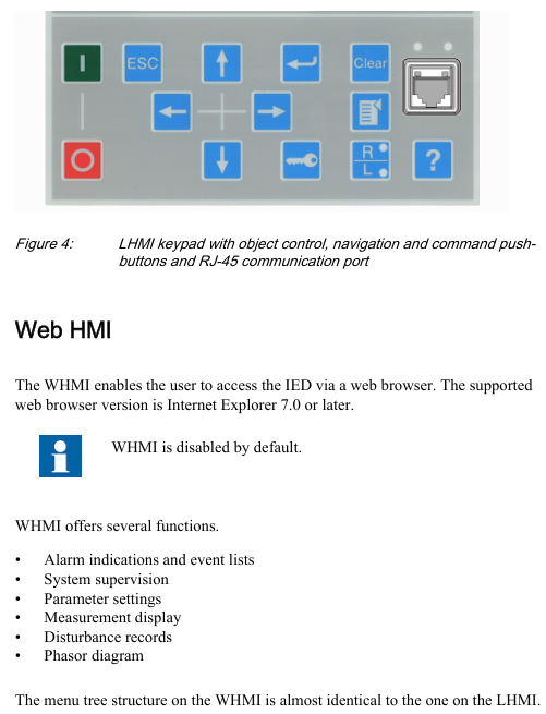
Key functions: navigation key (switching menu), control key (circuit breaker opening and closing), function key (alarm confirmation, reset, local/remote switching).
Web HMI(WHMI)
Access method: accessed through IE 7.0+browser, disabled by default, requires manual activation;
Core functions: parameter configuration, real-time measurement value viewing, disturbance record download, phasor diagram display, menu structure consistent with LHMI;
Access range: Local (connected to laptop via front-end RJ-45 port) or remote (via LAN/WAN).
(3) User Authorization
Four types of user permissions are preset, with authorization disabled by default (WHMI mandatory), and passwords can be changed by administrators:
Typical operations within the scope of username permissions
VIEWER read-only view of measurement values and alarm logs
OPEROTOR control and status switching, local/remote mode switching, alarm reset
ENGINEER configuration and testing modify parameters, clear disturbance records, enter testing mode
Administrator full permission to change password and restore factory settings
Core functions and standard configurations
(1) Three standard configuration schemes
RED615 provides three predefined configurations that cover different ground fault protection requirements, with the following core differences:
Configuration Type Core Protection Function Applicable Scenarios Key Modules
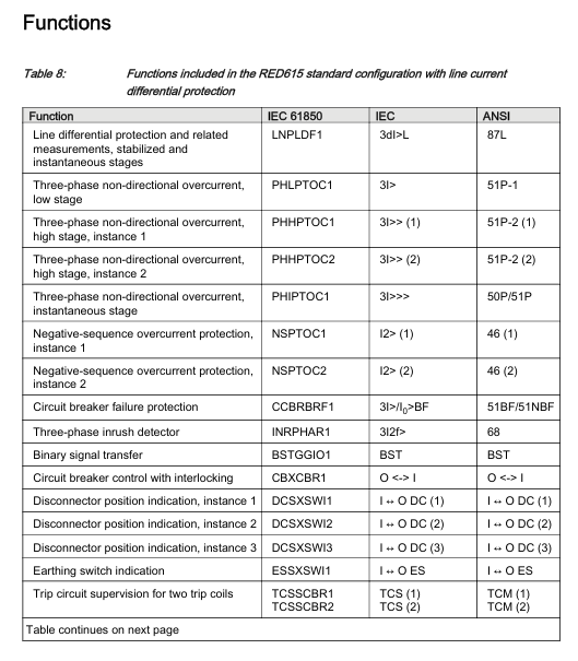
Configure A (line differential protection), including line differential protection (87L), three-phase overcurrent protection (50P/51P), negative sequence overcurrent protection (46), and circuit breaker failure protection (51BF), for cable feeders. In scenarios where ground fault protection is not required, there is no zero sequence voltage input and the CT synthesis of zero sequence current is relied upon
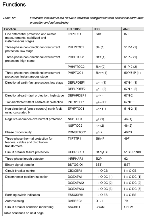
Configuration B (including directional grounding fault protection) Configuration A: All functions+directional grounding fault protection (67N), transient/intermittent grounding fault protection (67NIEF), automatic reclosing (79). For overhead lines/cable mixed lines, it is necessary to distinguish the fault direction of the power grid (such as multi power distribution network), including zero sequence voltage input (U ₀), and adapt to the compensation grounding system
Configuration C (including non directional grounding fault protection) Configuration A: All functions+non directional grounding fault protection (50N/51N), automatic reclosing (79), radiation type distribution network, no need to distinguish fault direction scenarios (such as single power supply feeders) rely on CT synthesized zero sequence current, no zero sequence voltage input
(2) Detailed explanation of key protection functions
Line differential protection (LNPLDF1, 87L)
Core function: As the main protection, it realizes unit protection of the line and quickly cuts off internal faults;
Features: Contains stable low order (can be locked by CT fault detection) and instantaneous high order (can dynamically adjust the action value through remote circuit breaker status);
Communication dependency: It is necessary to establish protective communication with the remote IED, which will automatically lock in case of communication failure to avoid misoperation.
Earth fault protection
Directional (configuration B): Based on the phase of zero sequence current (I ₀) and zero sequence voltage (U ₀), the fault direction is determined, suitable for multi terminal power grids, divided into low order (sensitive section) and high order (fast section);
Non directional (configuration C): Based solely on zero sequence current amplitude action, suitable for single ended power grids, divided into low order, high-order, and instantaneous order.
Automatic reclosing (DARREC1, 79, configuration B/C optional)
Starting condition: triggered by protection action signals (such as overcurrent, ground fault);
Locking logic: The circuit breaker spring is not storing energy, the gas pressure is low, and it is locked when manually opening;
Status indication: LED5 is lit during the reclosing process, and an alarm is triggered when it fails.
Circuit breaker related protection and monitoring
Circuit breaker failure protection (CCBRBRF1, 51BF/51NBF): When the circuit breaker is not opened after the protection action, a trip command is sent to the upstream circuit breaker;
Trip Circuit Monitoring (TCSSCBR1/2, TCM): Monitor 2 sets of trip coil circuits, and lock the monitoring function when the circuit breaker is opened;
Circuit breaker status monitoring (SSCBR1, CBCM): Based on current and contact status, the mechanical characteristics of the circuit breaker are determined, and an alarm is triggered when there is an abnormality.
Communication and Networking
(1) Protocol support
Protocol type, functional scope, physical interface
IEC 61850 monitoring, control, parameter configuration, disturbance record upload (COMTRADE format), GOOSE message (trip level delay ≤ 3ms) Ethernet (RJ-45100BASE-TX)
IEC 60870-5-103 Protection signal upload, telemetry and remote signaling RS-485 or Ethernet
Modbus RTU/ASCII third-party device interconnection (such as PLC, SCADA) RS-485 or RS-232
DNP3 telemetry, remote signaling, remote control, supporting TCP/IP or serial Ethernet or RS-485
(2) Precautions for Communication Networking
GOOSE application: supports the highest performance level (transmission delay ≤ 3ms), meets the tripping requirements of distribution substations, and can simultaneously send events to 5 clients;
Client limitation: A single IED can support up to 5 concurrent clients. After PCM600 occupies 1, the remaining 4 can be allocated to other protocol clients;
Time synchronization: Line differential protection requires remote station time reference synchronization, which is recommended to be implemented through IEC 61850 or SNTP.
- YOKOGAWA
- Reliance
- ADVANCED
- SEW
- ProSoft
- WATLOW
- Kongsberg
- FANUC
- VSD
- DCS
- PLC
- man-machine
- Covid-19
- Energy and Gender
- Energy Access
- Renewable Integration
- Energy Subsidies
- Energy and Water
- Net zero emission
- Energy Security
- Critical Minerals
- A-B
- petroleum
- Mine scale
- Sewage treatment
- cement
- architecture
- Industrial information
- New energy
- Automobile market
- electricity
- Construction site
- HIMA
- ABB
- Rockwell
- Schneider Modicon
- Siemens
- xYCOM
- Yaskawa
- Woodward
- BOSCH Rexroth
- MOOG
- General Electric
- American NI
- Rolls-Royce
- CTI
- Honeywell
- EMERSON
- MAN
- GE
- TRICONEX
- Control Wave
- ALSTOM
- AMAT
- STUDER
- KONGSBERG
- MOTOROLA
- DANAHER MOTION
- Bentley
- Galil
- EATON
- MOLEX
- Triconex
- DEIF
- B&W
- ZYGO
- Aerotech
- DANFOSS
- KOLLMORGEN
- Beijer
- Endress+Hauser
- schneider
- Foxboro
- KB
- REXROTH
- YAMAHA
- Johnson
- Westinghouse
- WAGO
- TOSHIBA
- TEKTRONIX
- BENDER
- BMCM
- SMC
- HITACHI
- HIRSCHMANN
- XP POWER
- Baldor
- Meggitt
- SHINKAWA
- Other Brands
- UniOP
- KUKA
- IBA
- Beckhoff
-
Basler Electric DECS-250-CN1SN1N Automatic Voltage Regulator for Generator Excitation Control
-
ADLINK CPCI-6860A - 51-31310-OB10 industrial motherboard CompactPCI SBC
-
ADLINK AmITX-SL-G-H110 - 51-7A104-0A30 Mini-ITX Industrial Motherboard
-
ADLINK PXI-2005-003 - CPCI Industrial PC Data Acquisition Card Multi-Function DAQ
-
ADLINK DININ-814M - 51-14032-0A3D SCSI-100P cable connection Interface Terminal Board
-
ADLINK CPCI-3920NA/C2D15/M1G - 3U CompactPCI Intel Core 2 Duo Single Board Computer
-
ADLINK PCIE-8560 - 51-18014-0A20 Communication Card High Speed DAQ
-
ADLINK PCI-C154+ - Motion Control Card 4-axis Motion Controller Board
-
ADLINK PCI-RTV24 - image capture card Analog Video Frame Grabber
-
ADLINK NuPRO-842LV/P - 51-41360-0B30 Industrial Motherboard CPU Board
-
ADLINK cBP-3208/3208R - CPCI Board 3U 8-Slot CompactPCI Backplane
-
ADLINK PCI-8164 - 4-Axis Motion Controller PCI Card 51-12406-0A40
-
ADLINK PCIe-GIE64+ - 4-CH GigE Vision PoE+ Frame Grabber Video Capture Card
-
ADLINK CPCI-6860 / 6860A - CompactPCI Dual Xeon Single Board Computer
-
ADLINK IEC-915GV - REV 1.1 Industrial motherboard CPU Board
-
ADLINK ND-6520 - Technology RS-232 to RS-422RS-485 Converter NuDAM Module
-
ADLINK RTV-24 / PCI-MP4S - 51-12519-1C30 4-Channel Real Time Video Capture Board
-
ADLINK cPCI-6910 / cPCI-6910AM/M1G - cPCI-6910AM/DXL16/M1G/S80G(G)-3120 BOARD CompactPCI SBC
-
ADLINK NUPRO-A40H - Linghua 51-41807-1A30 Industrial Control Computer Motherboard
-
ADLINK USB-3488A - USB to GPIB INTERFACE USB-3488A(G) Controller Module
-
ADLINK PCI-8134A - motion control card 4-Axis Controller Card
-
ADLINK PCI-7432 - Board 32-Channel input / 32-output Isolated Digital I/O PCI Card
-
ADLINK PCI-8134A - 51-12421-0A10 motion controller card tested
-
ADLINK LPCIe-7230 - 32 CH Isolated Input/output Card 2 Interrupts Low Profile PCIe
-
ADLINK NuPRO-E340 - industrial computer motherboard 51-47807-0A30 PICMG 1.3 SHB
-
ADLINK PCI-7434 - High-speed Digital Acquisition Card 64-CH Isolated DO Card
-
ADLINK NuPRO-E330 - 51-41805-0A20 Indsutrial Board SHB Single Board Computer
-
ADLINK PCI-7248 - OPTO-22 48 CHANNEL DIO DIGITAL TTL/DTL I/O 51-12006-0A40 GP
-
ADLINK PCI-8134 - Motion control card 4-Axis Controller Card
-
ADLINK AMP-208C - Movimiento Control Tarjeta 51-12420-1A20 W/Expansión & Breakout
-
ADLINK PCI-8164 - 51-12406-0A40 PCB Board 4-Axis Motion Controller Card
-
ADLINK DIN-68Y-SGII / DIN-68M-J3A - Terminal Board Connector Interface Block
-
ADLINK PCIe-7432 - Technology 51-18402-0A10 PCIe Card With High Input Range
-
ADLINK PCI-8144 / PCI-8144N - Motion control card 4-Axis Stepper Controller Card
-
ADLINK HSL-HUB3/REPEATER - HIGH SPEED LINK EXTENSION MODULES Distributed Hub Module
-
ADLINK ND-6017 - Data Logging + Acquisition 8CH A/D input Mod NuDAM Module
-
ADLINK LPCIe-7250 - data acquisition card Low Profile 8-CH Relay Output Card
-
ADLINK PCI-7432 - I/O card 64-CH Isolated Digital Input Output PCI Card
-
ADLINK IMB-M43H - industrial control computer motherboard Q87 Chip Micro-ATX
-
ADLINK MP-C154 - Motion control Card 4-Axis Motion Controller Board
-
ADLINK PCI-RTV24 - image capture card Video Frame Grabber Card
-
ADLINK PCI-7250 - 8-CH Relay Output & 8-CH Isolated DI Card
-
ADLINK PCI-6308V - 8-CH 12-Bit Isolated Analog Output PCI Card PCB-I-E-1148=6EX2
-
ADLINK PCI-7248 - capture card 48-CH Opto-22 Compatible DIO Card
-
ADLINK HSL-AI16A02-M-VV - Analog Input Output Distributed Module
-
ADLINK NuPRO-A301 - Rev:1.4 NUPRO-A301 PICMG Full-Size Single Board Computer
-
ADLINK PCI-6208V-GL - 8-CH Voltage Analog Output PCI Card
-
ADLINK PCI-8134A - 51-12421-0A10 4-Axis Motion Controller Card
-
ADLINK MNET-S23 - TECHNOLOGY MNET S23 - SERVO DRIVER CONTROL MODULE
-
ADLINK M-342 - ATX I3 I5 I7 Q67 Industrial Motherboard
-
ADLINK NUPRO-780 - Industrial Motherboard CPU Board PICMG SBC
-
ADLINK MP-C154 / MP-C152 - 4-Axis Motion Control Card Pulse-Train Controller
-
ADLINK NuPRO-935A/LV10B0 - Motherboard 51-41802-0A10 GP w/RAM Industrial Control Board
-
ADLINK MP-C154 - Motion control card 4-Axis Motion Controller Mainboard
-
ADLINK PCI-7250 - PCI Acquisition Card 8-CH Relay Output Isolated DI Card
-
ADLINK ACL-7124 - Technology Inc.24 DIO Card Digital Input Output Card
-
ADLINK PCI-8554 A2 - Timer/Counter Data Acquisition Card
-
ADLINK DIN-825-GP4 - Terminal Block Interface Board Breakout Module
-
ADLINK NuPR0-761 - REV:1.1 Industrial motherboard Full-Size PICMG SBC
-
ADLINK MXE-1401/M8G (G) - Matrix Fanless Embedded Computer Industrial PC
-
ADLINK HSL-DI16DO16-UD-NN - Digital 16 Channel I/O Mod Distributed I/O Module
-
ADLINK ND6520 - NUDAM INTELLIGENT DA&C MODULE RS232-RS-422/RS485 CONVERTOR
-
ADLINK NUPRO-761 - REV:1.1 Industrial Motherboard CPU Board
-
ADLINK AMP-208C - Motion Control Card 51-12420-1A20 DSP-based 8-axis
-
ADLINK NuPRO-A301REV 1.4 - with packaging industrial computer motherboard PICMG SBC
-
ADLINK PCM-9112+ - 51-12300-0A2 industrial motherboard Multi-Function DAQ PC/104 Module
-
ADLINK PCM-7250+ - 8-CH Relay Outputs & 8-CH Isolated DI Module PC/104
-
ADLINK PCI-RTV24 - Image capture card Analog Video Frame Grabber
-
ADLINK PCI-8134 - Motion Controller PCI Card 4-Axis Controller Board
-
ADLINK PCI-7432 - Isolated Digital I/O PCI Card
-
ADLINK PCI-8554 A2 - acquisition card Timer/Counter Card
-
ADLINK PCI-8132 - Rev.A2 2-Axis Servo & Stepper Motion Controller Card
-
ADLINK PCI-8132 - Data Acquisition card 2-Axis Motion Controller Card
-
ADLINK EBP-13E4 - 51-46703-0A30 Industrial Backplane Board Passive Backplane
-
ADLINK PCI-800L - Electronic Card Interface Controller Card
-
ADLINK PCIe-GIE72 - 51-18531-0A10 PCB Board GigE Vision Frame Grabber
-
ADLINK DAQ-2010(G)-OOBO - Simultaneous-Sampling Multi-Function DAQ Card
-
ADLINK PCI-9112 - REV.B1 Multifunction DAQ Card Data Acquisition Card
-
ADLINK PCI-7230 - 51-12003-DA60 32-CH Isolated Digital I/O Card
-
ADLINK PCI-7432 - Data Acquisition Card Isolated Digital I/O PCI Card
-
ADLINK ETX-AT-N270-18/LXE - 51-71111-0A20 ETX CPU Module Motherboard
-
ADLINK HSL-DI32-UD-N - DIGITAL INPUT 32 POINTS MODULE Distributed I/O
-
ADLINK AMP-204C - Motion Control card DSP-Based 4-Axis Advanced Controller
-
ADLINK MNET-4XMOG-0050 - Four-axis Motion Controller Distributed Motion Module
-
ADLINK AMP-204C - Motion control card DSP-Based 4-Axis Pulse-Train Controller
-
ADLINK PCI-7442 - Switch card 64-Channel Datalogging & Acquisition Card
-
ADLINK M-302 - Industrial control motherboard ATX PC Board
-
ADLINK NUPRO-852 / NUPRO-852LV - Industrial motherboard Single Board Computer
-
ADLINK PCI-8134 - REV.B1. 4-Axis Motion Controller Card
-
ADLINK PCI-GIE62 + - 51-18502-0A20 2-CH GigE Vision Frame Grabber PoE Card
-
ADLINK PCI-MPG24 - 51-12523-0B20 MPEG4 Card Video Compression Hardware
-
ADLINK HSL-TB32-M-DIN - 32-CH I/O TERMINAL W/ HSL-AI16AO2-M-VV MODULE
-
ADLINK PCI-M114-GL - PCB Ver 2.1 Motion Controller Axis Card
-
ADLINK IMB-M40H - SYM76996H61 motherboard Industrial Computer Mainboard
-
ADLINK NUPRO-A40H - 51-41807-1A20 industrial control motherboard H61 Chip
-
ADLINK PCI-M114-GL - Axis Card Data Acquisition Card PCB VER2.2 Motion Controller
-
ADLINK PCI-8134 - Motion Controller PCI Card 4-Axis Controller Board
-
ADLINK PCI-8102 - Motion control card 2-Axis Servo & Stepper Controller
-
ADLINK NuPRO-841REV:3.0 - motherboard Industrial Control PC Board
-
ADLINK HSL-TB32-U-DIN REV A1 - Breakout Terminal Board Field I/O Module
-
ADLINK AMP-204C - Motion Control card DSP-Based 4-Axis Pulse-Train Controller
-
ADLINK NUPRO-A40H - 51-41807-1A20 industrial control motherboard H61 PC Board
-
ADLINK PCI-6308A / PCI-6308V - 51-12202-0A50 Isolated Analog Output Card
-
ADLINK AMP-204C - DSP-Based 4-Axis Advanced Pulse-Train Motion Controller
-
ADLINK PCI-7434 - Technology 64-Channel Isolated Digital I/O PCI Cards
-
ADLINK CPCI-6840 / CPCI-6840V / PM16/M1G-12G0 - CompactPCI Single Board Computer CPU Module
-
ADLINK PCIE-GIE74 - Motherboard Video Capture Card 51-18531-0A10 Frame Grabber
-
ADLINK NuPRO-E330 - industrial computer equipment motherboard Control Mainboard
-
ADLINK AMP-208C / 51-12420-1A20 - Motion Control Card W/ Expansion & Breakout Board
-
ADLINK HPCI-14S12U - industrial computer baseboard Passive Backplane 14 Slots
-
ADLINK PCI-8164 - 4-Axis Motion Controller PCI Card W/ 1x Cable, 1x Breakout Box
-
ADLINK PCIe-RTV24 - 51-18016-0A20 Image Acquisition Video Capture Card
-
ADLINK M-342 - 5 PCI ATX Motherboard Industrial PC Mainboard
-
ADLINK PCI-FIW64 - 4/2 Channel IEEE1394B Image Capture Card FireWire Frame Grabber
-
ADLINK PCI-7432 - digital IO card 64-CH Isolated Digital Input Output Card
-
ADLINK 51-12001-0C20 - Circuit Board PCI-7200 Data Acquisition Controller Card
-
ADLINK PXI-3920 - PXI 3U cPCI Industrial Controller Embedded System CPU Board
-
ADLINK NuPRO-841REV:2.0 - motherboard Industrial Control PC Board
-
ADLINK NuPro-E330 - 51-41805-0A20 PCB Industrial Control Computer Motherboard
-
ADLINK PCI-RTV24 - Image capture card Analog Video Frame Grabber
-
ADLINK PCI-7442 - Switch card 64-Channel Datalogging & Acquisition Card
-
ADLINK HPX-13S4 - device baseboard Passive Backplane Riser Card
-
ADLINK PCI-9112 REV A.1 - Multi Function DA&C Board Data Acquisition Card
-
ADLINK PCI-7248 - 51-12006-0A40 Card Control 48-CH Digital I/O Module
-
ADLINK CPCI-6860 / 6860A - motherboard CompactPCI Dual Xeon Single Board Computer
-
ADLINK DPAC-3020-11(G) - Embedded PC Automation Controller Machine Control Board
-
ADLINK NuPRO-841 REV:1.0 - industrial control motherboard CPU Board
-
ADLINK MNET-4XMOG-0050 - Four-axis Motion Controller MNET Motion Control Card

K-JIANG

Add: Jimei North Road, Jimei District, Xiamen, Fujian, China
Tell:+86-15305925923