
K-WANG


Yokogawa 701944/701945 100:1 High Voltage Probe
Yokogawa 701944/701945 100:1 High Voltage Probe
Document Overview
This document is the user manual for Yokogawa 701944 and 701945 models 100:1 high-voltage probes (8th edition, released in May 2024), which is primarily used to guide users in safely and correctly using this series of probes. It covers key content such as product usage, safety specifications, structural configuration, operating procedures, maintenance methods, and technical parameters. The content of the manual may change with product performance upgrades, and the latest version needs to be obtained through the official website. It also provides access to user registration, technical support contact information, and multilingual supporting documents (such as Chinese specific documents and European language safety manuals).
Safety regulations and symbol explanations
(1) Symbol rules
Warning symbols: including Warning (indicating operations and preventive measures that may cause serious or fatal injuries), CAUTION (indicating operations and preventive measures that may cause minor injuries or equipment damage), Note (indicating important information for correct equipment operation), and providing French translation instructions, suitable for multilingual usage scenarios.
Equipment symbol: The "manual reference required" symbol marked on the equipment indicates the need to consult the manual for special operating instructions to ensure that users do not miss key safety guidelines.
(2) Core Security Guidelines
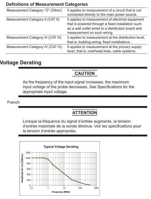
Scope of use: The probe can only be used in conjunction with an oscilloscope for observing and measuring electrical signals. It is strictly prohibited to use it beyond the specified range; Measurement category II defined in accordance with IEC 61010-031 standard cannot be used for category III or IV scenarios. When combined with equipment/accessories of different measurement categories, the lower category shall prevail.
Grounding requirements: The protective grounding terminal of the oscilloscope must be grounded, and the grounding wire of the probe must be connected to the grounding potential. Double grounding can effectively prevent the risk of electric shock and ensure measurement safety.
Electric shock protection: It is strictly prohibited to operate with wet hands or use the probe when it is damp; Be cautious of electric shock when connecting the tested device, and do not remove the probe from the oscilloscope when connecting it to the tested device; Avoid contact with exposed circuits and remove metal jewelry such as watches and rings during operation to prevent accidental electric shock.
Environmental restrictions: Do not use in damp, dusty, or flammable/explosive environments to prevent equipment failure or safety accidents; In terms of altitude, the working altitude should not exceed 2000m, and the storage altitude should not exceed 15000m; the working temperature should be between 0-50 ℃, the storage temperature should be between -40~71 ℃, and the humidity should meet the linear decreasing requirement of 80% (≤ 31 ℃) to 40% (50 ℃) to avoid environmental factors affecting measurement accuracy or damaging equipment.
Equipment status: If there is suspicion of probe damage (such as torn signal cables or exposed internal metal), immediately stop using and contact the dealer for repair; It is strictly prohibited to disassemble or modify the probe. Yokogawa shall not be held responsible for any malfunctions caused by unauthorized modifications; Strict adherence to the maximum input voltage limit (1000 Vrms) is required. When the oscilloscope input is coupled to AC, the DC voltage input by the probe will be synchronously applied to the oscilloscope input, ensuring that it does not exceed the maximum input voltage of the oscilloscope.
Product Overview and Configuration
(1) Product Features
701944 and 701945 are both high-voltage probes with a 100:1 attenuation ratio, and their core advantages include:
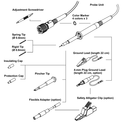
Probe tip design: Spring type tip (pre installed) can reduce pressure on the tested device, prevent sliding on the surface of the circuit board, and provide better stability when tilted for use; There are also options for rigid tips and clamp tips, suitable for different measurement scenarios.
Compatibility: Suitable for oscilloscopes with an input impedance of 1M Ω, the probe ID pin can be automatically recognized by the oscilloscope, and the oscilloscope attenuation ratio can be automatically set to 10:1 (manual adjustment is required if not automatically set).
Rich attachments: Provides a variety of standard and optional attachments to meet different measurement needs, and supports accessory replacement to extend the service life of the probe.
(2) Configuration List
Standard accessories: including probe body (701944/701945), spring tip (pre installed), rigid tip, clamp tip, insulation cap, protective cap (pre installed), grounding wire (22cm), color markings (4 colors x 3 pieces), adjustment tools and manual. All accessories must be confirmed complete and undamaged after unpacking to avoid affecting use.
Optional accessories: including flexible adapter, 4mm plug grounding wire, and safety crocodile clip, which need to be purchased separately and can be flexibly selected according to the measurement scenario.
Replacement accessory set: Two sets are available, "Accessories Basic" (B9852HK) including 2 spring tips, 2 rigid tips, 2 clamp tips, and 2 grounding wires; The "Accessories HV" (B9852HL) includes one flexible adapter, one 4mm plug grounding wire, and two safety crocodile clips, making it easy to replace accessories in bulk after wear and tear.
Operation process
(1) Basic Connection
Connection between probe and oscilloscope: Connect the BNC connector of the probe to the 1M Ω input port of the oscilloscope, ensuring that the input impedance of the oscilloscope is set to 1M Ω; the probe ID pin will be automatically recognized by the oscilloscope, and the attenuation ratio will be automatically set to 10:1. If it is not automatically set, it needs to be manually adjusted to the corresponding gear to ensure accurate measurement data.
Grounding connection: Connect the probe grounding wire to the grounding potential, which can only be used for grounding connection and cannot be used for other purposes; It is strictly prohibited to use non designated grounding wires to prevent measurement errors or safety risks caused by poor grounding.
(2) Calibration process
Low frequency compensation (LF Compensation): Connect the probe input to the probe compensation adjustment terminal (CAL/COMP terminal) of the oscilloscope, use the matching adjustment tool to rotate the low-frequency compensation micro adjuster, adjust the observed waveform to a standard square wave, ensure that the probe capacitance matches the oscilloscope input capacitance, and ensure measurement accuracy within the frequency range from DC to the upper limit of the bandwidth. Compensating for abnormalities (under compensation/over compensation) will cause waveform distortion and require readjustment.
HF Compensation: Calibration has been completed before leaving the factory. If adjustment is needed, a signal generator that can generate a fast rising edge rectangular wave needs to be connected. Slide the probe housing to expose the high-frequency compensation micro adjuster, and use an adjustment tool to smooth the rising edge to ensure the accuracy of high-frequency signal measurement.
DC Adjustment: Before leaving the factory, a measuring instrument with a 500VDC voltage source and a 1M Ω± 0.01% input impedance is used for calibration. Users do not need to make routine adjustments. If high-precision measurement is required, they can contact the dealer for professional calibration.
(3) Precautions for using the probe
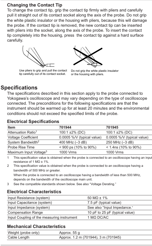
Tip replacement: When replacing the contact tip, it is necessary to clamp the tip with pliers and pull it out vertically along the axis of the probe. It is strictly prohibited to clamp the white plastic insulator or housing (to avoid damaging the probe); When inserting the new tip, align it with the socket along the axis and gently press it until it fully fits, ensuring good contact.
Cable protection: To prevent the probe body from being impacted, excessive bending or pulling of the cable is not allowed to prevent damage or breakage of internal circuits, which may affect signal transmission.
Voltage derating: When the input signal frequency increases, the maximum input voltage of the probe will decrease. It is necessary to refer to the "Voltage derating curve" to select the appropriate input voltage to avoid overvoltage damage to the probe; Pulse measurement must comply with the corresponding limitations of peak pulse voltage, duty cycle, and duration to ensure safe use.
Maintenance and disposal
(1) Daily maintenance
Cleaning: When cleaning the probe housing, only a soft cloth dipped in water or isopropanol can be used to wipe it. After wiping, it must be completely dry before it can be used for measurement. Volatile chemicals such as benzene and diluents should not be used to prevent corrosion or deformation of the housing.
Accessory inspection: Regularly check whether the probe tip, grounding wire, and cable are intact. If the tip is worn, the cable is cracked, or the grounding wire is aged, the corresponding accessories should be replaced in a timely manner to avoid affecting measurement accuracy or causing safety hazards.
(2) Disposal of waste
When discarding probes or accessories, it is necessary to comply with the laws and regulations of the country/region where they are located and not to dispose of them at will; Components belonging to electronic waste, such as probe bodies and cables, must be disposed of in accordance with local electronic waste disposal regulations to avoid environmental pollution and comply with the EU WEEE Directive and relevant environmental requirements of each country.
Technical parameters
(1) Electrical parameters
Parameter 701944 701945 Remarks
Attenuation ratio 100:1 ± 2% (DC) 100:1 ± 2% (DC) requires the connection of an oscilloscope with an input impedance of 1M Ω± 1%
The typical value of voltage coefficient is 0.0005%/V, which reflects the influence of voltage changes on the attenuation ratio. The smaller the coefficient, the higher the accuracy
When the system bandwidth is -3dB, an oscilloscope with a bandwidth ≥ 500MHz needs to be connected to 400MHz and 250MHz, otherwise it is limited by the oscilloscope bandwidth
When the rise time of the probe is 10%~90%, it is less than 900ps. When it is 10%~90%, it is less than 1.4ns. The shorter the rise time, the faster the high-frequency signal response
The maximum input voltage is 1000Vrms. The voltage derating curve should be referenced for 1000Vrms, and the input voltage should be reduced at high frequencies
System input resistance 50M Ω± 1% 50M Ω± 1% ensures matching with oscilloscope input impedance
The typical value of system input capacitance is 7.5pF, which affects the stability of high-frequency signal measurement
Compensation range typical value 10pF~25pF typical value 10pF~25pF adapted to different oscilloscope input capacitors
(2) Mechanical and environmental parameters
Weight: The probe body weighs about 55g, lightweight and easy to operate, reducing fatigue from prolonged use.
Cable length: 701944 is about 1.2m, 701945 is about 3m, suitable for different measurement distance requirements. The long cable model (701945) is more suitable for long-distance measurement scenarios.
Protection standard: Complies with EN 61010-031 safety standard, measurement category II, transient voltage 4000V; complies with the EU RoHS directive, environmentally friendly and free of harmful substances.
Input impedance characteristics: It decreases with the increase of input signal frequency, and reference should be made to the "input impedance curve". When measuring at high frequencies, attention should be paid to the impact of impedance changes on the measurement results.
- YOKOGAWA
- Reliance
- ADVANCED
- SEW
- ProSoft
- WATLOW
- Kongsberg
- FANUC
- VSD
- DCS
- PLC
- man-machine
- Covid-19
- Energy and Gender
- Energy Access
- Renewable Integration
- Energy Subsidies
- Energy and Water
- Net zero emission
- Energy Security
- Critical Minerals
- A-B
- petroleum
- Mine scale
- Sewage treatment
- cement
- architecture
- Industrial information
- New energy
- Automobile market
- electricity
- Construction site
- HIMA
- ABB
- Rockwell
- Schneider Modicon
- Siemens
- xYCOM
- Yaskawa
- Woodward
- BOSCH Rexroth
- MOOG
- General Electric
- American NI
- Rolls-Royce
- CTI
- Honeywell
- EMERSON
- MAN
- GE
- TRICONEX
- Control Wave
- ALSTOM
- AMAT
- STUDER
- KONGSBERG
- MOTOROLA
- DANAHER MOTION
- Bentley
- Galil
- EATON
- MOLEX
- Triconex
- DEIF
- B&W
- ZYGO
- Aerotech
- DANFOSS
- KOLLMORGEN
- Beijer
- Endress+Hauser
- schneider
- Foxboro
- KB
- REXROTH
- YAMAHA
- Johnson
- Westinghouse
- WAGO
- TOSHIBA
- TEKTRONIX
- BENDER
- BMCM
- SMC
- HITACHI
- HIRSCHMANN
- XP POWER
- Baldor
- Meggitt
- SHINKAWA
- Other Brands
- UniOP
- KUKA
- IBA
- Beckhoff
-
LTI SC52.0040.0012.0000.0 - Servo Drive
-
Lti SC52.0040.0012.0000.0 - Servo Drive
-
Milton Industries LTI Tool By Milton LT1240 - 1/2" Drive Lugnut Remover
-
LTi Drives SO84.200.P030.0000.0-W - Servo Spindle Drive
-
LTI DRIVES LSP08-035-320-30-B0R1PY170 - Servo Motor
-
LTI DRIVES SE84.200.SC00.0001.0-W - Servo Drive
-
Lust CDE34.005.W2.2 - Lti Drives Controller
-
LTi SO84.012.0030.0011.2 - ServoOne Servo Drive
-
LTi Drives SO CM-P.0010.11.00.0 - Servo Drive Controller
-
LTi CDE34.017.W3.0 - Servo Drive
-
LTI Drives CDB32.004, C2.0,SH - Positioning Controller
-
LUST CM-CAN1 - LTi DRIVES Communication Module
-
LTi SO84.012.1030.0000.2 - Servo Drive
-
LTI MOOG CDE54.044 - PITCHMASTER FREQUENCY CONVERTER 181-01019
-
MOOG LTI 181-01019 CDE54.044 - PITCHMASTER FREQUENCY CONVERTER
-
Lust LTi Drives CDE34.010,D2.0 - Servo Drive Controller
-
LTI SO84.032.0003.0101.2 - Servo Drive
-
Seagate 9CC132-302 Harris LTI-CS IRT-34-0021-01 - Hard Drive 160GB
-
LTI SO84.032.0003.0001.2 - Servo Drive
-
LTI SO24.007.0070.0000.1 - SERVO CONTROLLER
-
LTi drive CDA32.003.C3.0.H05-01.PC1 - Servo Drive
-
LTI SO84.016.0030.0000.2 - SERVO CONTROLLER
-
LUST LTI CD A34.008,W1.4, BR - SERVO DRIVE
-
MOOG LTI 181-01019 CDE54.044 - PITCHMASTER FREQUENCY CONVERTER
-
LTI MOOG 181-01019 - PITCH Master Servo Drive CDE54.044
-
LTI SERVO ONE SO84.045.0030.0001.2-W - Drive
-
LUST LTi SO84.032.0040.0000.2 - SERVO ONE DRIVE
-
LTi Drives LSH-074-2-30-3 20/T1,G6.1M - SERVO MOTOR
-
LTI SO84.016.0000.0101.2 - servo drive
-
LTI SA54.0550.0033.0000.0 - Servo Drive
-
LTI SA54.0550.0033.0000.0 - Servo Drive
-
LTI LT 4850 - 3/8" Drive 3-Pc Twist Socket Transmission Drain Plug Removal System
-
LTI Tools LT4400-30 Lock Technology - 3/4" Twist Socket 1/2" Drive Lugnut Remover
-
LTI Tools LT-1400C - 1/2 Drive Wheel Torque Extension Tool
-
LTI Tools LT1250 - 1/2" Drive Dual Sided Socket Lug Nut Remover Tool
-
LTI SO84.032.0003.0101.2 - Servo Drive
-
LTI MOOG 181-01019 - PITCH Master Servo Drive CDE54.044
-
MOOG LTI 181-01019 CDE54.044 - PITCHMASTER FREQUENCY CONVERTER
-
MOOG LTI 181-01019 CDE54.044 - PITCHMASTER FREQUENCY CONVERTER
-
MOOG LTI 181-01019 CDE54.044 - PITCHMASTER FREQUENCY CONVERTER
-
LTI SA54.0550.0033.0000.0 - Servo Drive
-
LTI Tools LT-4800 - 7 Piece Twist Socket 3/8" Drive Oil Drain Plug Removal Set
-
LTI SA54.0550.0033.0000.0 - Servo Drive
-
LTI Drive SO24.007.00300000.0 - Servo Drive
-
LTI TOOLS LTI 1400-I - Drive Wheel Torque Extension
-
LTI Tools LT4400-3 - 3/4" 19mm Twist Socket 1/2" Drive Lugnut
-
LTI TOOLS LTI 1400-BB - Drive Wheel Torque Extension
-
LTI SO84.032.0003.0101.2 - Servo Drive
-
LTI Tools LT-4512 - 3/8" Drive 12mm Twist Socket
-
LTI MOTION Luster SO84.032.0003.0001.2 - Servo Drive
-
LTI Tool By Milton LT1600P - 1" Drive Torx Stick
-
LTI Lust VF1424L,HF,OP2,S56 - Variable Frequency Drive
-
LUST CDA32.004,C1.4,H08,B0 - SERVO DFRIVE CM-CAN1 Module
-
LTI SO84.045.0002.0001.2-W - Drive
-
LTI Lust VF1404M,C9,PT1,BR1 - Inverter Type VF1404M
-
LTI SA54.0550.0033.0000.0 - Servo Drive
-
LTI Tools LT-1400C - 1/2" Drive Wheel Torque Extension
-
Lust LTI DRiVES CDA32.006, C3.0, H09 - Variateur De Fr茅quence Frequency Inverter
-
LTI MOOG CDE54.044 - PITCH master SERVO DRIVE
-
LTI MOOG CDE54.044 - PITCH master SERVO DRIVE
-
LTI SO84.143.0020.0101.2-W - servo drive
-
LTI MOTION SC34.0200.0011.0000.0 - Servo drives
-
LTI SO84.032.0003.0001.2 - Servo Drive
-
LTI DRIVES GmbH MS100 - Assembly Set Mounting Kit
-
LTI SO84.032.0003.0001.2 - Servo Drive
-
LTI SO84.032.0003.0001.2 - Servo Drive
-
LTI MOTION SO84.032.0003.0101.2 - servo drive
-
LTI SO84.032.0003.0101.2 - Servo Drive
-
LTI MOOG CDE54.044 - PITCH master SERVO DRIVE
-
LTI MOTION CDE32.004.C2.4 - Servo drives
-
LTI CDD34.032锛學x.x锛孊R锛孭C1 - Servo Drive
-
Lust LTI DRiVES CDA32.006, C3.0, H09 - Inversor De Frecuencia Frequency Inverter
-
Lust SO84.008.0030.1000.0 - Servo One LTi Drive
-
LTI MOTION SO84.032.0003.0101.2 - Servo drives
-
LUST LTi CDA32.004,C1.4 - SERVO DRIVE
-
LTI MOOG CDE54.044 - PITCH Master SERVO DRIVE
-
LTI KEBA CDB32.004 C2.7, SH - PN: 08673530 Frequency Inverter
-
LTI Tools LT-1400C - 1/2" Drive Wheel Torque Extension
-
LTI LT1400-E - 1/2" Drive Wheel Torque Extension
-
LTI MOOG 181-01019 - PITCH master SERVO DRIVE CDE54.044
-
LTI LSN-097-0510-30-560/T1 - Actuator Motor
-
LTI Tools LT 4800 - 7 Piece 3/8" Drive Twist Socket Oil Drain Plug Removal System
-
LTI DRIVES GmbH MS100 - MONTAGESET Assembly Set Mounting Kit
-
Lti SC52.0040.0012.0000.0 - Servo Drive
-
LTI DRIVES GmbH MS100 - Juego De Montaje Assembly Set Mounting Kit
-
LTi DSM4-14.2-21R83-200 - Drives servomoteur Servo Motor
-
MOOG CDE 54.044.GDA - Pitch Master Industrielle Turbine Lti Drive
-
LTI SO24.004.0030.1000.0 - Servo Drive Controller
-
Lti MOOG CDE54.044 - Pitch Master Servo Drive
-
Lust LTI DRiVES CDA32.006, C3.0, H09 - Inverter
-
LTI MOTION GMBH CDB34.006,W3.0,PC1,H39 - Frequency inverter
-
LTI SO84.032.0003.0001.2 - Servo Drive
-
MOOG CDE 54.044.D - Pitch Master Industrielle Turbine Lti Drive
-
LTI TOOLS LT-1460 - 1/2" DRIVE WHEEL TORQUE EXTENSION KIT 5 PIECE SET
-
Lust Cdb32.003, C2.4 - Lti Drives Servoregulador Frecuencia Servo Controller Inverter
-
Lust LTI DRIVES CDA32.006, C3.0, H09 - Frequency Inverter
-
Lust Lti SO82.004.0030.0000.2 - Servo Drive
-
LTI MOTION SC34.0200.0011.0000.0-SL - Servo drives
-
LTI MOTION SA54.0075.0033.0000.0 - Servo drives
-
LTI MOTION SC32.0075.1011.0000.0 - Servo drives
-
LTI Servo-One Junior SO22.006.0080.1000.0 - Servo Controller Servoregler
-
LUST CDA32.004, C1.4, H08, B0 - Servo Drive & LTI CM-CAN1 Module
-
LTI DRIVES LSP08-035-320-30-B0R1PY170 - Servo Motor
-
LUST LTI CDA32.004,C1.4.H08.B0 - SERVO CONTROLLER DRIVES
-
LUST LTi DRiVES CDS44.072LC1.2 - Servo Drive
-
Lti Servo-One Junior SO22.006.0082.1000.0 - Servo Controller Servoregler
-
LUST CDA32.008,C2.0,HF - Lti DRIVES Spindle Drive Inverter
-
LTI SO22.003.0082.0000.0 - Servo Drives One junior Servo Controller Servoregler
-
Lust Lti Drives CM-CAN1 - Communication Module
-
LUST Lti Drives Vf1202s, G8, I6 - Frequency Inverter Drive
-
LTI DRIVES BR-090.03.540.UR.H38 - Bremswiderstand Brake Resistor
-
LTi DRIVES PM-E40.2DRA054P - Wind Turbine Pitch Control Inverter
-
LTi Drives GmbH br-110.01.540-UR - Brake Resistor
-
LTI Drives LSN-097-0960-30-0560/T1,S4,B - Servo Motor
-
LUST CDA34.006.C2.0 - LTI Drives Servoregler
-
LUST LTI DRIVES SERVO ONE JUNIOR SO24.002.0020.0000.1 - Servo Drive Controller
-
LTI MOTION SO84.032.0003.0001.2 - Servo drives
-
LTI DDTD750V2-120 - IBOP ACTUATOR CYLINDER FOR TOP DRIVE
-
LTI CDE32.004, C2.4 - SERVO DRIVE
-
LUST LTI DRIVES CDD34.017 W3.4PC1 - Servo Drive Controller
-
LTI CDA3208,C3,0,HF - AC SERVO DRIVE
-
LUST LTI DRIVES LSH-074-3-30-560/T1,G6.1S - SERVO MOTOR
-
LUST Lti CDB32.004.C2.4.SH - AC Servo Drive
-
LTi CDA32.006, C3.0, H09 - Servo Drive
-
LTI SO22.003.0010.0000.0 - Servo Drive Servo one junior Servoregler Controller
-
LTi Drives DSM4-14.2-21R83-200 - Servo Motor
-
LUST Lti Drives Lsh-097-1-30-560/T1, 1R - Servomotor
-
LTI 1237 - 7 Piece 1/2" Drive Flip Socket Set

K-JIANG

Add: Jimei North Road, Jimei District, Xiamen, Fujian, China
Tell:+86-15305925923