
K-WANG


Yokogawa CA700 pressure calibrator
Yokogawa CA700 pressure calibrator
Overview
This document is an introductory guide for Yokogawa CA700 pressure calibrator (11th edition, released in May 2024). Its core function is to guide users in safely operating the equipment, covering key content such as product packaging inspection, safety specifications, basic operating procedures, pressure transmitter calibration methods, troubleshooting, and technical parameters. The content of the manual may change with product performance upgrades, and the latest version needs to be obtained through the official website. It also provides access to user registration, technical support contact information, and multilingual supporting documents (such as Chinese specific documents and European language safety manuals).
Product packaging and model identification
(1) Packaging inspection
Product confirmation: After unboxing, the equipment model and suffix code need to be checked. Model CA700 is the basic model of the pressure calibrator, and the suffix code includes the region (- E corresponds to regions other than Japan), pressure specification (-01 is 200kPa gauge pressure, -02 is 1000kPa gauge pressure, -03 is 3500kPa gauge pressure), unit type (- U1 is international unit, - U2 is international and non international unit), input interface (- P1 is Rc1/4 internal thread, - P2 is 1/4NPT internal thread), which needs to be confirmed to be consistent with the order based on the equipment nameplate (located on the back panel).
Standard accessories: including signal cable (98064, red and black pair), shoulder strap (B8070CY), adapter connector (91080/91081 adapter - P1 interface, 91082 adapter - P2 interface), 6 AA alkaline dry batteries (A1070EB), accessory box (B9108XA), ferrite core (A1193MN, 2 pieces), pressure input port cover (L4060CL, pre installed in the equipment) and various documents. It is necessary to confirm that the accessories are complete and have no external damage. Standard accessories do not enjoy equipment warranty service.
Optional accessories: Includes low-pressure manual pump kit (91070, including pump, box, connector), pneumatic pressure pump kit (91074, including pump, box, connector), hydraulic pressure pump kit, etc., which need to be purchased separately and do not enjoy equipment warranty. Some accessories (such as PM100 series shielding meter models) require equipment firmware version support (-05 requires 1.10 or above, -06 requires 1.20 or above).
(2) Connector specifications
The external dimensions of the adapter connector (91080/91081/91082) have clear standards, such as a length of 26.9mm, a diameter of 7.1mm, and a surface engraved with the "NPT" symbol; 91081 length 36.1mm, diameter 7.1mm, also engraved with "NPT"; The size of 91082 is the same as 91080 but without identification. It should be selected correctly according to the interface type to avoid pressure leakage caused by improper connection.
Safety regulations and symbol explanations
(1) Symbol rules
Unit distinction: The prefix "k" represents 1000 (e.g. 100 kS/s, sampling rate), and "K" represents 1024 (e.g. 720 KB, file size); Bold characters in the operation steps represent panel buttons, soft keys, and screen menu options, making it easy for users to quickly locate the operation object.
Warning symbols: including Warning (indicating operations and preventive measures that may cause serious or fatal injuries), CAUTION (indicating operations and preventive measures that may cause minor injuries, equipment damage, or data loss), Note (indicating important information for correct equipment operation), and providing French reference instructions, suitable for multilingual usage scenarios.
Equipment symbol: The "Caution" symbol marked on the equipment indicates the need to refer to the manual for special operating instructions; The grounding symbol is a functional grounding terminal (cannot be used as a protective grounding); The AC/DC symbol and power switch symbol correspond to AC/DC input and power control respectively, and must be strictly operated according to the symbol instructions.
(2) Core Security Guidelines
Scope of use: The device is only used for pressure equipment calibration and can measure and generate DC current/voltage, measure pressure. It is strictly prohibited to use beyond the range. If it cannot be used to measure the main power supply or belongs to measurement categories II, III, IV, the device measurement category is "Other (O)" and is only suitable for circuits that are not directly connected to the main power supply.
Environmental restrictions: The equipment protection level is IP54 and cannot be used in environments beyond this level; The working temperature range is -10~50 ℃, humidity is 20%~80% (non condensing), and the working altitude does not exceed 2000m. It belongs to Class A industrial environment products and may cause radio interference when used in residential areas. Users need to solve the interference problem by themselves.
Pressure safety: When measuring high-pressure fluids, it is necessary to use pressure resistant pipelines and connectors, check for leaks and ensure that the joints are tight. Gas measurements of 1MPa and above must comply with high-pressure gas safety regulations; It is strictly prohibited to measure flammable, explosive, toxic, corrosive fluids and high-temperature fluids/gas-liquid mixtures above 50 ℃. Gas measurement must ensure dryness and cleanliness, and avoid high humidity and high oil content air; The pressure input should not exceed the allowable range (e.g. CA700-01 allows positive pressure of 500kPa, CA700-02 is 3000kPa, CA700- * -03 is 4500kPa). Overpressure may cause equipment damage or personal injury.
Operating standards: It is strictly prohibited to dismantle the equipment casing or modify the internal structure. There is high voltage in some areas of the interior, and maintenance needs to be done by contacting the dealer; When the device is abnormal (such as smoking, odor), it is necessary to immediately turn off the power and remove the battery; Long term non use requires removal of the battery to avoid leakage and damage to the equipment; When cleaning, only use a soft cloth that has been wrung out to wipe the casing. Do not use volatile chemicals such as benzene or diluents to prevent discoloration or deformation of the casing.
Equipment structure and function
(1) Panel layout
Front panel: Includes direct buttons (ZERO key for pressure zero calibration, HOLD key for freezing measurement values, MIN/MAX key for displaying/clearing maximum values, RELATED key for displaying relative values, SOURCE/EASURE key for switching source and measurement mode), input/output terminals (voltage input terminal, current/voltage output terminal, current input terminal, common terminal), direction keys (adjust value, move cursor), ENTER key (confirm operation), ESC key (return/cancel), function keys (corresponding to menu options at the bottom of the screen), power key, backlight key, and LCD display screen. The functions of each button are clear, and the operation logic conforms to the usual usage habits of measuring equipment.
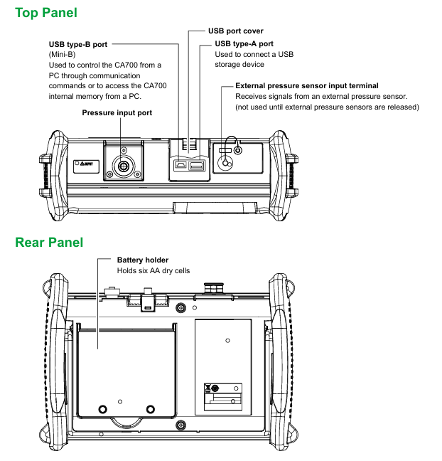
Top panel: equipped with a USB port cover, which includes a USB Type-B interface (Mini-B, used for PC to control devices or access internal storage through commands), a USB Type-A interface (connected to USB storage devices), an external pressure sensor input terminal (not yet enabled, to be used after external sensors are released), and a pressure input port. The port cover needs to be kept closed to ensure IP54 protection level.
Rear panel: equipped with a battery compartment (accommodating 6 AA dry batteries), the battery compartment cover needs to be removed with a cross screwdriver. When replacing the battery, pay attention to polarity and operate it before cutting off power and disconnecting all cables.
(2) Display screen function
Main menu: Display the main menu after power on, including measurement and source settings, pressure transmitter/switch calibration settings, file management (copy/delete files, format internal storage), device settings (automatic shutdown, screen contrast, USB configuration, data saving options, product information, firmware upgrade), which can be navigated and selected through the directional keys and ENTER key.
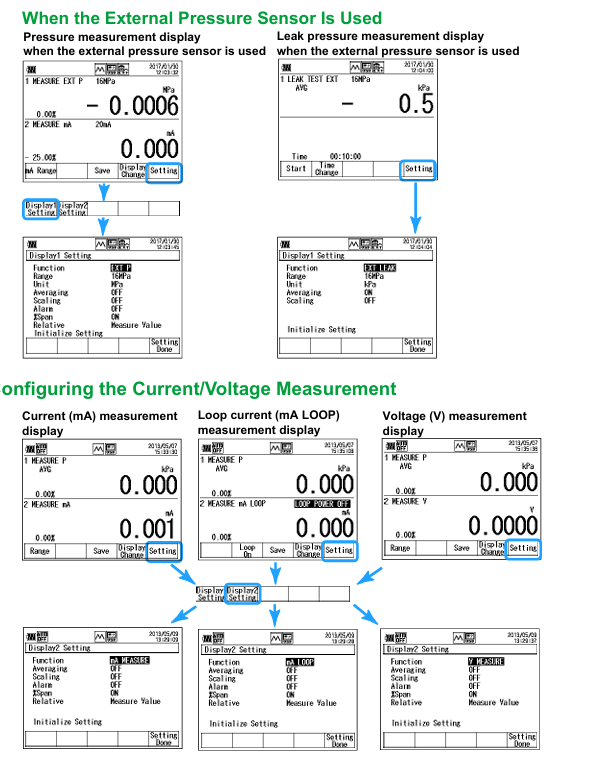
Display partition: In measurement and source mode, the upper half of the screen displays pressure measurement (Display 1), while the lower half displays current/voltage measurement/source (Display 2). When measuring leakage pressure, only Display 1 is displayed; You can switch between full screen Display 1 or Display 2 by pressing the Display Change (F4) key. When displaying separately, press the Setting (F5) key to enter the corresponding settings interface.
Icon display: The icon area at the top of the screen displays USB status (communication/storage mode, host mode), scanning mode (step/linear), battery remaining power, automatic shutdown status, hold status, internal resistance (250 Ω) status, and external pressure sensor connection status. The icons intuitively reflect the current working parameters of the device, making it easy for users to quickly grasp the device status.


Operation preparation and basic settings
(1) Equipment installation
Installation requirements: It should be placed on a stable horizontal surface to ensure that the equipment is level in all directions during pressure measurement. Tilting or unstable placement may cause pressure measurement errors; The installation location should be easy to quickly remove the battery in case of abnormal situations, and comply with the IP54 protection level environment, avoiding scenarios of water immersion and excessive dust; Do not use in areas with high wind speed or frequent airflow to prevent a decrease in measurement accuracy.
Shoulder strap installation: The shoulder strap needs to be threaded through the hanging rings on the upper left and upper right sides of the device, then threaded through the buckle and tightened in the opposite direction to ensure a secure installation and facilitate the movement and carrying of the device. When carrying, the tested device and CA700 should be closed first, all cables removed, and placed in a dedicated carrying case to avoid violent collisions.
(2) Power management
Battery installation: Confirm that the device is powered off and the wireless cable is connected. Use a Phillips screwdriver to open the back panel battery compartment cover, insert 6 AA alkaline dry batteries according to the polarity instructions, close the compartment cover and tighten the screws; Do not mix old and new batteries or batteries of different brands/types to prevent leakage, heating, or bursting; If not used for a long time (more than 1 month), the battery should be removed to avoid leakage and damage to the internal circuit.
Power control: Press the power button on the front panel to turn on the device, and the device will automatically perform self check and calibration. After success, the main menu will be displayed; To shut down, press and hold the power button until the "Power Off?" prompt appears. Press the ENTER key to confirm the shutdown, and the device will save the settings before shutdown. It will automatically resume the next time it is turned on; After starting up, it is necessary to preheat for at least 30 minutes to ensure measurement accuracy, and avoid high-precision measurement operations during the preheating period.
Battery level indicator: The screen icon area displays the remaining battery level through the battery icon. If the battery level is too low, it needs to be replaced in a timely manner. When the battery is depleted, the current measurement data may not be saved; When the current or voltage source function is turned on, battery consumption accelerates. It is necessary to prepare a backup battery in advance to avoid interruption of the calibration process.
(3) Connection and Calibration
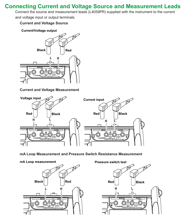
Cable connection: Before connecting, the power supply of the device under test must be turned off. The current/voltage source and the measurement cable (standard L4059PR) must be correctly connected to the corresponding terminals. The current/voltage output should be connected to the "Source mA/V" and "COM" terminals, the current input should be connected to the "MEASURE mA" and "COM" terminals, and the voltage input should be connected to the "MEASURE V" and "COM" terminals; The pressure input port needs to be equipped with a suitable connector according to the interface type. Before connection, it is necessary to wrap sealing tape and use two wrenches to fix the port and connector separately to prevent damage to the internal structure of the equipment. After connection, it is necessary to check for leaks.
Date and Time Setting: Select "Device Setting" from the main menu and press ENTER to enter the device settings menu. Page to the second page and select "Date Format" to set the date display format (such as YYYY/MM/DD). Then set "Date" and "Time" separately, adjust the values using the directional keys, press ENTER to confirm, and finally press "Setting Done (F5)" to save the settings. Date and time are used for data recording and file naming, ensuring accuracy.
Zero point calibration: Before pressure measurement, zero point calibration needs to be performed, keeping the equipment in the measurement posture (horizontal placement, front panel facing up or tilted with back panel support), opening the pressure input port, pressing the ZERO key on the pressure measurement display interface, confirming the prompt, pressing the ENTER key to perform calibration, and pressing the ESC key to cancel; When the ambient temperature or equipment posture changes, recalibration is required. When measuring liquids, the pipeline and equipment should be filled with liquid before calibration; After connecting the external pressure sensor, it is also necessary to perform zero calibration separately. Please refer to the sensor manual for the operation method.
Calibration process of pressure transmitter
(1) Connection configuration
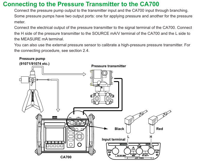
Hardware connection: The output of the pressure pump needs to be connected to both the pressure transmitter input and the CA700 pressure input port through a branch pipeline. Some pressure pumps come with dual output ports (for pressurization and pressure measurement respectively); The electrical output terminal of the pressure transmitter needs to be connected to the CA700 signal terminal, the H terminal of the transmitter should be connected to the "Source mA/V" terminal of CA700, and the L terminal should be connected to the "Measure mA" terminal; High pressure transmitter calibration can use external pressure sensors, which need to be connected to the external pressure sensor input terminal of the device with a dedicated cable when CA700 is powered off. After the device is turned on, the corresponding icon will be displayed when the sensor is successfully recognized.
(2) Calibration settings
Program selection: Select "Calibrate" from the main menu and press the ENTER key to enter the calibration interface. Press the "Select Proc. (F2)" key to display a list of registered calibration programs (up to 20 groups). Use the page flipping and directional keys to select the program to be edited, press the ENTER key to view program information, and then press the "Edit (F1)" key to enter the settings interface. The interface is divided into three pages: "Transmitter Information", "Measure", and "Source", which can be switched by long pressing the directional keys.
Device Information Settings: On the "Transmitter Information" page, enter the model number (up to 20 characters), tag number (up to 32 characters), and serial number (up to 15 characters). Use the arrow keys to move the input position, press ENTER to confirm the character input, and then press "Done (F5)" to save; The device information will be saved to a file along with the calibration data, making it easier to associate and trace the data with the device.
Measurement and source condition settings: The "Measure" page requires setting measurement functions (such as mA LOOP), averaging (default OFF), scaling (default OFF), output values corresponding to 0% and 100% (such as 4mA and 20mA), and tolerance (based on the percentage difference between 0% and 100%); The "Source" page is used to set the source function (pressure calibration needs to be set to P, and the device only monitors pressure rather than generates pressure), pressure units (such as kPa, bar, etc.), input pressure values corresponding to 0% and 100%, calibration points (1-10 points), calibration direction (Up is 0% → 100%, Down is 100% → 0%, Up/Down is 0% → 100% → 0%). When setting in the Up/Down direction, the calibration points automatically change to "Setting Points × 2-1", and all settings need to be confirmed by pressing "Setting Done (F5)".
(3) Calibration execution
Data saving before calibration: Press the "As Found (F3)" button on the calibration interface to switch to the source and measurement value display interface. Press the "Loop On (F4)" button to output the 24VDC circuit voltage and measure the circuit current. Apply calibration point pressure (such as 50.000kPa) from the pressure pump, press the "Set Point (F1)" button to save the current pressure and current values, press the "Next Point (F2)" button to enter the next calibration point, repeat the operation until all points are completed, and finally press the "Done (F5)" button to save the data as a CSV file (file name format MSxxF_y.CSV, xx is the calibration group number, y is the sequence number), and display the calibration results.
Transmitter adjustment: Press the "Adjust (F4)" key to enter the adjustment interface, select the adjustment point through the "Span100% (0%) (F1)", "Step Up (F2)", "Step Down (F3)" keys, press the "Loop On (F4)" key to activate loop measurement, apply corresponding pressure and adjust the transmitter to make the loop current within the tolerance range. After all points are adjusted, press the "Adjust Done (F5)" or ESC key to return.
Data saving after calibration: Press the "As Left (F5)" key and repeat the "pre calibration data saving" step to save the adjusted data in the file format of MAxxL_y.CSV, with the same number as the pre calibration file xx, for easy comparison of differences before and after calibration; The data includes calibration conditions, equipment information, date and time, input/output values at each point, error percentage, and qualified results (PASS/FAIL). When the error exceeds the tolerance, it is marked as FAIL.
Troubleshooting and Maintenance
(1) Common problem solving
Power related issues: If the device cannot be turned on, check the battery level and installation polarity; Automatic shutdown after startup requires battery replacement; If the screen is dim, adjust the contrast (refer to section 6.1 of the download manual IM CA700-01EN) or press the backlight button to turn on the backlight.
Display and operation related issues: If the display is abnormal, it is necessary to confirm that the environmental temperature and humidity meet the requirements, avoid noise interference, check cable connections, and restart the device; Press the HOLD key to exit hold mode if there is no response to the button; Abnormal measurement/source values require checking the battery level, function settings, source and circuit power on status, and correct connection to ensure that the equipment is preheated for more than 30 minutes.
USB and communication issues: USB devices or communication abnormalities need to be shut down, removed, restarted, and reconnected. After power failure, wait for more than 10 seconds before restarting; The communication interface cannot be configured or controlled, and the address settings need to be checked to ensure that the program address is consistent with the device address, and that the interface complies with electrical and mechanical specifications.
(2) Error codes and handling
Communication errors: Code 11 (instruction error), 12 (parameter error), and 13 (execution error) are all related to USB communication. It is necessary to check the correctness of the instruction and whether the current device status supports the instruction; Code 16 (adjustment error), 50 (pressure sensor error), 51 (tilt sensor error), 52 (A/D converter error) need to be repaired by contacting the dealer.
Source and storage class errors: Code 20 (24V circuit power supply error), 23 (source output overcurrent/overvoltage) need to check the connection; Code 24 (insufficient power supply) requires battery replacement; Code 33 (full storage) and 34 (storage error) require checking the storage destination, clearing space, or replacing the storage device; External pressure sensor communication, memory, and measurement errors require reconnecting the sensor, restarting the device, or replacing the cable, which cannot be resolved and requires repair.
(3) Maintenance and disposal
Regular maintenance: It is recommended to replace the backup lithium battery (for memory backup) every 5 years and contact the dealer for operation; To ensure measurement accuracy, it is recommended to calibrate once a year. For details on measuring DC voltage/current and calibrating the source function, please refer to the IM CA700-01EN manual.
Equipment disposal: Abandoned equipment must comply with the laws and regulations of the country or region where it is located and cannot be discarded at will; Batteries need to be disposed of separately according to local waste battery disposal standards to avoid environmental pollution.
Technical parameters
(1) Core functional parameters
Pressure measurement: Different models have different measurement ranges. The -01 model has a positive pressure of 0-200kPa and a negative pressure of -80~0kPa, the -02 model has a positive pressure of 0-1000kPa and a negative pressure of -80~0kPa, and the -03 model has a positive pressure of 0-3500kPa and a negative pressure of -80~0kPa; The accuracy after 6 months of zero drift is ± (0.01% reading+0.003kPa) (20-200kPa)/± 0.005kPa (0-20kPa), ± (0.01% reading+0.04kPa), ± (0.01% reading+0.15kPa) for positive pressure, and ± (0.2% reading+0.08kPa) for negative pressure; The resolutions are 0.001kPa, 0.01kPa, and 0.01kPa respectively, with a response time of ≤ 2.5 seconds. The allowable input pressures are 2.7kPa absolute pressure to 500kPa gauge pressure, 2.7kPa absolute pressure to 3000kPa gauge pressure, and 2.7kPa absolute pressure to 4500kPa gauge pressure. The measuring medium is non corrosive, non flammable, non explosive, and non-toxic gases and liquids, with a medium temperature of -10~50 ℃ (liquid 5~50 ℃).
DC current/voltage source: current source (20mA range) accuracy 0.015% set value+3 μ A, analog output accuracy is the same, compliance voltage 24V (HART resistor OFF)/18V (HART resistor ON); Voltage source (5V range) accuracy 0.015% set value+0.5mV, load current ≤ 1mA; temperature coefficient is accuracy × (1/10)/℃ (-10~20 ℃, 26~50 ℃), source load needs to meet C ≤ 0.1 μ F, L ≤ 10mH, ground voltage 42Vpeak, current limit about 30mA, supports step and linear scanning.
DC current/voltage measurement: current (20mA range) accuracy 0.015% reading+3 μ A, 100mA range accuracy 0.015% reading+30 μ A; Voltage (5V range) accuracy of 0.015% reading+0.5mV, 50V range accuracy of 0.015% reading+5mV; circuit measurement provides 24V ± 1V (HART resistor OFF)/24V ± 6V (HART resistor ON) power supply, measurement accuracy of 0.015% reading+3 μ A, temperature coefficient same source function, common mode suppression ratio of about 120dB (50/60Hz), series mode suppression ratio of about 60dB (50/60Hz), input terminal with PTC protection, maximum input voltage of 50Vpeak, current of 120mA.
(2) General parameters
Storage capacity: Manual storage, logging, and leak testing can each save 2000 pieces of data. As Found and As Left for transmitter calibration (5 points) can each save 9 pieces of data, and pressure switch calibration can each save 1 piece of data. The total number of files is up to 250, with a total data volume of approximately 3.5MB.
Display and interface: Dot matrix LCD display screen (320 × 240 pixels), LED backlight, display update rate of about 300ms/time; Supports USB A (storage device) and USB mini B (communication/storage) interfaces, with external sensor interfaces used to connect dedicated sensors.
Physics and Environment: Dimensions approximately 264mm (width) x 188mm (height) x 96mm (depth), weight approximately 2kg; operating temperature and humidity -10~50 ℃, 20%~80% RH (non condensing), storage temperature and humidity -20~60 ℃, 20%~80% RH (non condensing); Insulation resistance ≥ 100M Ω (500VDC), withstand voltage 500VAC/1 minute, in compliance with EN 61010-1 safety standard, EMC in compliance with EN 61326-1 Class A, EN 55011 Class A standards, and in compliance with the EU RoHS directive.

- YOKOGAWA
- Reliance
- ADVANCED
- SEW
- ProSoft
- WATLOW
- Kongsberg
- FANUC
- VSD
- DCS
- PLC
- man-machine
- Covid-19
- Energy and Gender
- Energy Access
- Renewable Integration
- Energy Subsidies
- Energy and Water
- Net zero emission
- Energy Security
- Critical Minerals
- A-B
- petroleum
- Mine scale
- Sewage treatment
- cement
- architecture
- Industrial information
- New energy
- Automobile market
- electricity
- Construction site
- HIMA
- ABB
- Rockwell
- Schneider Modicon
- Siemens
- xYCOM
- Yaskawa
- Woodward
- BOSCH Rexroth
- MOOG
- General Electric
- American NI
- Rolls-Royce
- CTI
- Honeywell
- EMERSON
- MAN
- GE
- TRICONEX
- Control Wave
- ALSTOM
- AMAT
- STUDER
- KONGSBERG
- MOTOROLA
- DANAHER MOTION
- Bentley
- Galil
- EATON
- MOLEX
- Triconex
- DEIF
- B&W
- ZYGO
- Aerotech
- DANFOSS
- KOLLMORGEN
- Beijer
- Endress+Hauser
- schneider
- Foxboro
- KB
- REXROTH
- YAMAHA
- Johnson
- Westinghouse
- WAGO
- TOSHIBA
- TEKTRONIX
- BENDER
- BMCM
- SMC
- HITACHI
- HIRSCHMANN
- XP POWER
- Baldor
- Meggitt
- SHINKAWA
- Other Brands
- UniOP
- KUKA
- IBA
- Beckhoff
-
LTI SC52.0040.0012.0000.0 - Servo Drive
-
Lti SC52.0040.0012.0000.0 - Servo Drive
-
Milton Industries LTI Tool By Milton LT1240 - 1/2" Drive Lugnut Remover
-
LTi Drives SO84.200.P030.0000.0-W - Servo Spindle Drive
-
LTI DRIVES LSP08-035-320-30-B0R1PY170 - Servo Motor
-
LTI DRIVES SE84.200.SC00.0001.0-W - Servo Drive
-
Lust CDE34.005.W2.2 - Lti Drives Controller
-
LTi SO84.012.0030.0011.2 - ServoOne Servo Drive
-
LTi Drives SO CM-P.0010.11.00.0 - Servo Drive Controller
-
LTi CDE34.017.W3.0 - Servo Drive
-
LTI Drives CDB32.004, C2.0,SH - Positioning Controller
-
LUST CM-CAN1 - LTi DRIVES Communication Module
-
LTi SO84.012.1030.0000.2 - Servo Drive
-
LTI MOOG CDE54.044 - PITCHMASTER FREQUENCY CONVERTER 181-01019
-
MOOG LTI 181-01019 CDE54.044 - PITCHMASTER FREQUENCY CONVERTER
-
Lust LTi Drives CDE34.010,D2.0 - Servo Drive Controller
-
LTI SO84.032.0003.0101.2 - Servo Drive
-
Seagate 9CC132-302 Harris LTI-CS IRT-34-0021-01 - Hard Drive 160GB
-
LTI SO84.032.0003.0001.2 - Servo Drive
-
LTI SO24.007.0070.0000.1 - SERVO CONTROLLER
-
LTi drive CDA32.003.C3.0.H05-01.PC1 - Servo Drive
-
LTI SO84.016.0030.0000.2 - SERVO CONTROLLER
-
LUST LTI CD A34.008,W1.4, BR - SERVO DRIVE
-
MOOG LTI 181-01019 CDE54.044 - PITCHMASTER FREQUENCY CONVERTER
-
LTI MOOG 181-01019 - PITCH Master Servo Drive CDE54.044
-
LTI SERVO ONE SO84.045.0030.0001.2-W - Drive
-
LUST LTi SO84.032.0040.0000.2 - SERVO ONE DRIVE
-
LTi Drives LSH-074-2-30-3 20/T1,G6.1M - SERVO MOTOR
-
LTI SO84.016.0000.0101.2 - servo drive
-
LTI SA54.0550.0033.0000.0 - Servo Drive
-
LTI SA54.0550.0033.0000.0 - Servo Drive
-
LTI LT 4850 - 3/8" Drive 3-Pc Twist Socket Transmission Drain Plug Removal System
-
LTI Tools LT4400-30 Lock Technology - 3/4" Twist Socket 1/2" Drive Lugnut Remover
-
LTI Tools LT-1400C - 1/2 Drive Wheel Torque Extension Tool
-
LTI Tools LT1250 - 1/2" Drive Dual Sided Socket Lug Nut Remover Tool
-
LTI SO84.032.0003.0101.2 - Servo Drive
-
LTI MOOG 181-01019 - PITCH Master Servo Drive CDE54.044
-
MOOG LTI 181-01019 CDE54.044 - PITCHMASTER FREQUENCY CONVERTER
-
MOOG LTI 181-01019 CDE54.044 - PITCHMASTER FREQUENCY CONVERTER
-
MOOG LTI 181-01019 CDE54.044 - PITCHMASTER FREQUENCY CONVERTER
-
LTI SA54.0550.0033.0000.0 - Servo Drive
-
LTI Tools LT-4800 - 7 Piece Twist Socket 3/8" Drive Oil Drain Plug Removal Set
-
LTI SA54.0550.0033.0000.0 - Servo Drive
-
LTI Drive SO24.007.00300000.0 - Servo Drive
-
LTI TOOLS LTI 1400-I - Drive Wheel Torque Extension
-
LTI Tools LT4400-3 - 3/4" 19mm Twist Socket 1/2" Drive Lugnut
-
LTI TOOLS LTI 1400-BB - Drive Wheel Torque Extension
-
LTI SO84.032.0003.0101.2 - Servo Drive
-
LTI Tools LT-4512 - 3/8" Drive 12mm Twist Socket
-
LTI MOTION Luster SO84.032.0003.0001.2 - Servo Drive
-
LTI Tool By Milton LT1600P - 1" Drive Torx Stick
-
LTI Lust VF1424L,HF,OP2,S56 - Variable Frequency Drive
-
LUST CDA32.004,C1.4,H08,B0 - SERVO DFRIVE CM-CAN1 Module
-
LTI SO84.045.0002.0001.2-W - Drive
-
LTI Lust VF1404M,C9,PT1,BR1 - Inverter Type VF1404M
-
LTI SA54.0550.0033.0000.0 - Servo Drive
-
LTI Tools LT-1400C - 1/2" Drive Wheel Torque Extension
-
Lust LTI DRiVES CDA32.006, C3.0, H09 - Variateur De Fr茅quence Frequency Inverter
-
LTI MOOG CDE54.044 - PITCH master SERVO DRIVE
-
LTI MOOG CDE54.044 - PITCH master SERVO DRIVE
-
LTI SO84.143.0020.0101.2-W - servo drive
-
LTI MOTION SC34.0200.0011.0000.0 - Servo drives
-
LTI SO84.032.0003.0001.2 - Servo Drive
-
LTI DRIVES GmbH MS100 - Assembly Set Mounting Kit
-
LTI SO84.032.0003.0001.2 - Servo Drive
-
LTI SO84.032.0003.0001.2 - Servo Drive
-
LTI MOTION SO84.032.0003.0101.2 - servo drive
-
LTI SO84.032.0003.0101.2 - Servo Drive
-
LTI MOOG CDE54.044 - PITCH master SERVO DRIVE
-
LTI MOTION CDE32.004.C2.4 - Servo drives
-
LTI CDD34.032锛學x.x锛孊R锛孭C1 - Servo Drive
-
Lust LTI DRiVES CDA32.006, C3.0, H09 - Inversor De Frecuencia Frequency Inverter
-
Lust SO84.008.0030.1000.0 - Servo One LTi Drive
-
LTI MOTION SO84.032.0003.0101.2 - Servo drives
-
LUST LTi CDA32.004,C1.4 - SERVO DRIVE
-
LTI MOOG CDE54.044 - PITCH Master SERVO DRIVE
-
LTI KEBA CDB32.004 C2.7, SH - PN: 08673530 Frequency Inverter
-
LTI Tools LT-1400C - 1/2" Drive Wheel Torque Extension
-
LTI LT1400-E - 1/2" Drive Wheel Torque Extension
-
LTI MOOG 181-01019 - PITCH master SERVO DRIVE CDE54.044
-
LTI LSN-097-0510-30-560/T1 - Actuator Motor
-
LTI Tools LT 4800 - 7 Piece 3/8" Drive Twist Socket Oil Drain Plug Removal System
-
LTI DRIVES GmbH MS100 - MONTAGESET Assembly Set Mounting Kit
-
Lti SC52.0040.0012.0000.0 - Servo Drive
-
LTI DRIVES GmbH MS100 - Juego De Montaje Assembly Set Mounting Kit
-
LTi DSM4-14.2-21R83-200 - Drives servomoteur Servo Motor
-
MOOG CDE 54.044.GDA - Pitch Master Industrielle Turbine Lti Drive
-
LTI SO24.004.0030.1000.0 - Servo Drive Controller
-
Lti MOOG CDE54.044 - Pitch Master Servo Drive
-
Lust LTI DRiVES CDA32.006, C3.0, H09 - Inverter
-
LTI MOTION GMBH CDB34.006,W3.0,PC1,H39 - Frequency inverter
-
LTI SO84.032.0003.0001.2 - Servo Drive
-
MOOG CDE 54.044.D - Pitch Master Industrielle Turbine Lti Drive
-
LTI TOOLS LT-1460 - 1/2" DRIVE WHEEL TORQUE EXTENSION KIT 5 PIECE SET
-
Lust Cdb32.003, C2.4 - Lti Drives Servoregulador Frecuencia Servo Controller Inverter
-
Lust LTI DRIVES CDA32.006, C3.0, H09 - Frequency Inverter
-
Lust Lti SO82.004.0030.0000.2 - Servo Drive
-
LTI MOTION SC34.0200.0011.0000.0-SL - Servo drives
-
LTI MOTION SA54.0075.0033.0000.0 - Servo drives
-
LTI MOTION SC32.0075.1011.0000.0 - Servo drives
-
LTI Servo-One Junior SO22.006.0080.1000.0 - Servo Controller Servoregler
-
LUST CDA32.004, C1.4, H08, B0 - Servo Drive & LTI CM-CAN1 Module
-
LTI DRIVES LSP08-035-320-30-B0R1PY170 - Servo Motor
-
LUST LTI CDA32.004,C1.4.H08.B0 - SERVO CONTROLLER DRIVES
-
LUST LTi DRiVES CDS44.072LC1.2 - Servo Drive
-
Lti Servo-One Junior SO22.006.0082.1000.0 - Servo Controller Servoregler
-
LUST CDA32.008,C2.0,HF - Lti DRIVES Spindle Drive Inverter
-
LTI SO22.003.0082.0000.0 - Servo Drives One junior Servo Controller Servoregler
-
Lust Lti Drives CM-CAN1 - Communication Module
-
LUST Lti Drives Vf1202s, G8, I6 - Frequency Inverter Drive
-
LTI DRIVES BR-090.03.540.UR.H38 - Bremswiderstand Brake Resistor
-
LTi DRIVES PM-E40.2DRA054P - Wind Turbine Pitch Control Inverter
-
LTi Drives GmbH br-110.01.540-UR - Brake Resistor
-
LTI Drives LSN-097-0960-30-0560/T1,S4,B - Servo Motor
-
LUST CDA34.006.C2.0 - LTI Drives Servoregler
-
LUST LTI DRIVES SERVO ONE JUNIOR SO24.002.0020.0000.1 - Servo Drive Controller
-
LTI MOTION SO84.032.0003.0001.2 - Servo drives
-
LTI DDTD750V2-120 - IBOP ACTUATOR CYLINDER FOR TOP DRIVE
-
LTI CDE32.004, C2.4 - SERVO DRIVE
-
LUST LTI DRIVES CDD34.017 W3.4PC1 - Servo Drive Controller
-
LTI CDA3208,C3,0,HF - AC SERVO DRIVE
-
LUST LTI DRIVES LSH-074-3-30-560/T1,G6.1S - SERVO MOTOR
-
LUST Lti CDB32.004.C2.4.SH - AC Servo Drive
-
LTi CDA32.006, C3.0, H09 - Servo Drive
-
LTI SO22.003.0010.0000.0 - Servo Drive Servo one junior Servoregler Controller
-
LTi Drives DSM4-14.2-21R83-200 - Servo Motor
-
LUST Lti Drives Lsh-097-1-30-560/T1, 1R - Servomotor
-
LTI 1237 - 7 Piece 1/2" Drive Flip Socket Set

K-JIANG

Add: Jimei North Road, Jimei District, Xiamen, Fujian, China
Tell:+86-15305925923