
K-WANG


Yokogawa DL350 Scope Order Communication Interface
Yokogawa DL350 Scope Order Communication Interface
Overview
This document is the Yokogawa DL350 Scope Order Communication Interface User Manual (6th edition, released in April 2024), which focuses on the Ethernet and USB communication interface functions of the device. It provides detailed guidance for users to complete interface configuration, remote control programming, and status monitoring. At the same time, it provides a supporting document system, technical support channels, and version revision records to ensure that users can safely and efficiently operate the device remotely through the communication interface.

Safety regulations and symbol explanations
(1) Warning symbols and their meanings
The manual adopts a three-level warning system and provides French reference to ensure clear safety guidance in multilingual scenarios
Warning: Operations that may cause serious or fatal injuries, such as operating high-voltage circuits without grounding, using equipment in flammable environments, etc., must strictly follow preventive measures.
CAUTION: Indicates operations that may cause minor injury or equipment/data damage, such as wet hand operation interfaces, improper cable connections, etc.
Note: Key information indicating the correct operation of the device, such as communication interfaces that cannot be used simultaneously, command execution sequence requirements, etc.
Equipment symbol: The "manual reference required" symbol marked on the equipment indicates that the operation needs to refer to the manual for special guidance to avoid missing key steps.
(2) Core Security Guidelines
Scope of use: The communication interface is only used to connect with a PC for remote control, and it is strictly prohibited to use it beyond the designated range; The equipment complies with measurement category II of IEC 61010-031 standard and cannot be used in category III/IV scenarios. When paired with equipment of different categories, the lower category shall prevail.
Grounding requirements: The oscilloscope protection grounding terminal must be reliably grounded, and the probe grounding wire must be connected to the grounding potential. Double grounding can effectively prevent the risk of electric shock.
Environmental restrictions: The working environment must meet the temperature range of 0-50 ℃, humidity range of 20% -80% RH (non condensing), and storage environment temperature range of -40~71 ℃; It is strictly prohibited to use in damp, dusty, flammable/explosive gas environments. The working altitude should not exceed 2000m, and the storage altitude should not exceed 15000m.
Equipment status: If any signs of damage such as damaged interface cables or exposed metal are found, immediately stop using and contact the dealer for repair; It is strictly prohibited to disassemble or modify communication interface components. Yokogawa shall not be held responsible for any malfunctions caused by unauthorized modifications.
Communication interface function and configuration
(1) Ethernet interface
1. Core features and parameters
Function: Supports remote reception of device setting instructions, acquisition of measurement data (such as waveform data, panel configuration) and status information (such as device error codes, operating status), and remote transmission of measurement results and status bytes.
Technical specifications: 1 RJ-45 port, compliant with IEEE 802.3 standard, maximum data rate of 100Mbps, communication protocol is TCP/IP; The transmission rate of waveform data varies depending on the data format. For example, the transmission of byte data for 1 million data points takes about 100ms, while ASCII data takes about 30s.
2. Connection and configuration
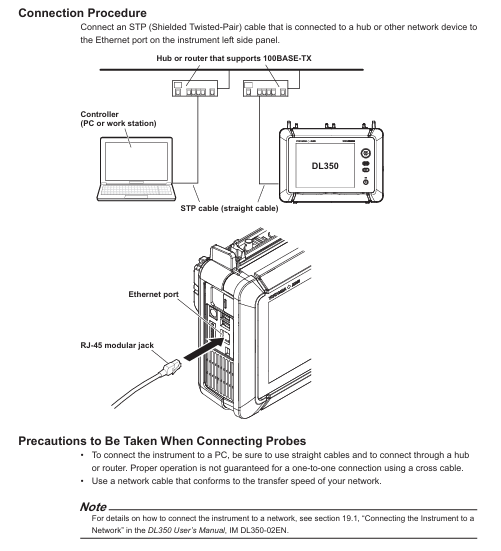
Hardware connection: Use shielded twisted pair (STP) to connect the Ethernet port on the left panel of the device to the hub/router, and then connect to the PC; direct cables are required, and it is not recommended to directly connect the PC to the device through crossover cables.
Parameter settings: TCP/IP parameters (IP address, subnet mask, default gateway) and network timeout time need to be configured. Set the timeout period through the device menu "Utility>Network>VXI11" to ensure stable communication during remote control.
3. Remote/Local Mode Switching
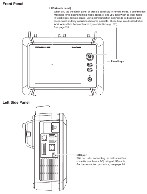
Switching logic: When the PC sends the "COMMunicate: REMote ON" command, the device enters remote mode, and "Remote" is displayed at the top of the screen. At this time, touch panel/button operations can only trigger the "Release Remote Mode" confirmation pop-up window; Send "COMMunicate: REMote OFF" or click "OK" in the pop-up window to switch back to local mode.
Mode restriction: In remote mode, if the PC sends the ": Communicate: LOCKout ON" command, the local operation will be locked and can only be released through the PC command; When switching between two modes, the current device settings will be retained without the need for reconfiguration.
(2) USB interface
1. Core features and parameters
Function: Consistent with Ethernet interface function, supports remote command reception, data transmission, and status monitoring, but requires additional driver installation.
Technical specifications: 1 Mini Type B port, compliant with USB 2.0 standard, device in self powered mode; Only supports Windows 8.1/10/11 system PC, requires installation of Yokogawa USB driver (YKMUSB) and communication library (TMCTL); The waveform transmission rate is slightly higher than Ethernet, with a byte data transmission time of about 700ms for 1 million data points and about 25s for ASCII data.
2. Connection and configuration
Hardware connection: Use a USB Mini B cable to connect the USB port on the left panel of the device to the PC. If multiple devices are connected through a USB hub, connect the DL350 to the hub port near the PC to avoid signal attenuation; Do not plug or unplug USB cables within 20-30 seconds after the device is turned on (not fully started) to prevent damage to the device.
Parameter setting: Set "USB Function" to "TMC" through the device menu "Utility>System>Others". After setting, restart the device to take effect; PC requires the installation of corresponding drivers, which can be obtained through the official website or by contacting distributors. The use of third-party USB drivers is prohibited.
3. Remote/Local Mode Switching
Switching logic: Completely consistent with the Ethernet interface, confirm the switch through PC commands or local pop ups, and retain the current settings when switching modes.
Exclusive restriction: Ethernet and USB interfaces cannot be used simultaneously. When one interface is enabled, the other interface will be automatically disabled.
Fundamentals of Programming and Instruction System
(1) Core Programming Concepts
1. Message format
Program message: sent from a PC to a device, containing one or more instruction units separated by semicolons, and ending with a termination symbol (NL, ^ END, or NL ^ END); Each instruction unit consists of "program header+space+program data", such as "ACQuire: MODE NORMal" (set the acquisition mode to normal mode).
Response message: returned by the device to the PC, corresponding to the query instruction in the program message, in the format of "response header+space+response data" (some queries only return data), terminated with NL ^ END at the end; If the program message contains multiple queries, the response will be returned in the order of the queries.
2. Data type
Supporting multiple data formats to adapt to different control requirements, the key types and descriptions are as follows:
Example of Data Type Format Explanation
Decimal numbers (<Decimal>) consist of integers (NR1), fixed-point numbers (NR2), and floating-point numbers (NR3). The device can receive any format, and the response is uniformly set to NR3 with a sampling rate of "TIMebase: SRATE 1E6"
Physical quantities (such as<Voltage>/<Time>) are numerical values prefixed with units or multiples, and units/prefixes are not case sensitive. Set the timeline as "TIMebase: TDIV 1US"
Register>supports decimal, hexadecimal (# H), octal (# Q), and binary (# B), and responds by uniformly setting events in decimal: "STATus: EESE # H01"
Pre defined mnemonic for character data (<Character data>), to be selected from options, case insensitive setting coupling method: "CHANnel1: COUPling AC"
Boolean value (<Boolean>) supports ON/OFF or numerical values (0=OFF, non-zero=ON), and the response uniformly uses 0/1 to open the channel display: "CHANnel1: DISPlay ON"
The string (<String data>) needs to be enclosed in single/double quotation marks. If it contains quotation marks, two consecutive setting labels should be entered: "CHANnel1: LABel" CH1_TEST "
Block data (<Block data>) 8-bit binary data, formatted as "# N+N bit data length+data byte sequence", only used to respond to waveform data response: "# 800000010ABCDEFGHIJ"
(2) Instruction system
The manual divides instructions into 37 command groups, covering full remote control functions such as device acquisition, analysis, display, and triggering. The core command groups and functions are as follows:
Command Group Core Instruction Function Description
ACQuire Group: ACQuire: MODE, ACQuire: LENGTH Set/query waveform acquisition mode (normal/average/envelope), recording length (oscilloscope mode)
ANALysis Group :ANALysis:HARMonic:FREQuency、:ANALysis:HARMonic:RESult? Configure harmonic analysis frequency, query harmonic RMS/power analysis results (such as total distortion rate, active power)
CHANnel Group: CHANnel<x>: COUPling, CHANnel<x>: SCALe sets channel input coupling (AC/DC/GND), screen display upper and lower limits, supports voltage, temperature, strain and other modules
TRIGger Group: TRIGger: MODE, TRIGger: LEVel Configure trigger mode (single/repeated), trigger level, supports multiple trigger types such as edge, pulse width, etc
WAVeform Group :WAVeform:SEND? 、 WAVeform: FORMat queries waveform data and sets data transmission format (byte/word/ASCII)
SYSTem Group :SYSTem:CLOCk:DATE、:SYSTem:BATTery:REMain? Set device date and time, check battery remaining level
Common Command Group *IDN? 、 *CLS, OPC standard IEEE 488.2 command, query device model, clear status register, mark operation completed
Status monitoring and troubleshooting
(1) Status reporting mechanism
The device achieves status monitoring through status bytes, registers, and queues. The core components include:
Status byte: 8-bit binary data, reflecting the overall operating status of the device, such as bit0 indicating operation completion and bit5 indicating error occurrence.
Standard event register: records device standard events (such as operation completion, query errors), which can be enabled through "* ESE" and queried and cleared through "* ESR?".
Extended event register: records device specific events (such as collection completion, trigger occurrence), enabled through the "STATus: EESE" setting, cleared through the "STATus: EESR?" query.
Output and Error Queue: The error queue stores the latest error code and description, which can be queried through "STATus: ERRor?"; The output queue stores non error messages, which can be set to be stored or not through ": STATus: QENable".
(2) Common problem solving
Troubleshooting steps for problem types and phenomena
Communication connection issue: Ethernet/USB cannot establish a connection. 1. Check if the cable connection is secure, and confirm if the Ethernet IP address is in the same network segment; 2. USB needs to confirm whether the driver is installed correctly and whether the device's "USB Function" is set to "TMC"; 3. Restart the device and PC and try again
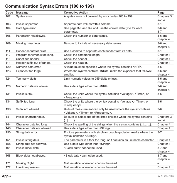
Instruction execution problem: Sending instructions without response or error. 1. Check the instruction syntax (such as case and parameter range), refer to Chapter 4 of the manual to confirm the instruction format; 2. Confirm that the device is in remote mode and there is no local lock; 3. Check the communication timeout setting. If the data volume is large, the timeout time can be extended
Data transmission issue: waveform data transmission interruption or distortion. 1. Confirm that the transmitted data format is consistent with the supported format of the device (such as byte/word/ASCII); 2. Ethernet needs to check network bandwidth to avoid transmitting large amounts of data simultaneously; 3. USB requires the use of short distance cables to reduce signal attenuation
- YOKOGAWA
- Reliance
- ADVANCED
- SEW
- ProSoft
- WATLOW
- Kongsberg
- FANUC
- VSD
- DCS
- PLC
- man-machine
- Covid-19
- Energy and Gender
- Energy Access
- Renewable Integration
- Energy Subsidies
- Energy and Water
- Net zero emission
- Energy Security
- Critical Minerals
- A-B
- petroleum
- Mine scale
- Sewage treatment
- cement
- architecture
- Industrial information
- New energy
- Automobile market
- electricity
- Construction site
- HIMA
- ABB
- Rockwell
- Schneider Modicon
- Siemens
- xYCOM
- Yaskawa
- Woodward
- BOSCH Rexroth
- MOOG
- General Electric
- American NI
- Rolls-Royce
- CTI
- Honeywell
- EMERSON
- MAN
- GE
- TRICONEX
- Control Wave
- ALSTOM
- AMAT
- STUDER
- KONGSBERG
- MOTOROLA
- DANAHER MOTION
- Bentley
- Galil
- EATON
- MOLEX
- Triconex
- DEIF
- B&W
- ZYGO
- Aerotech
- DANFOSS
- KOLLMORGEN
- Beijer
- Endress+Hauser
- schneider
- Foxboro
- KB
- REXROTH
- YAMAHA
- Johnson
- Westinghouse
- WAGO
- TOSHIBA
- TEKTRONIX
- BENDER
- BMCM
- SMC
- HITACHI
- HIRSCHMANN
- XP POWER
- Baldor
- Meggitt
- SHINKAWA
- Other Brands
- UniOP
- KUKA
- IBA
- Beckhoff
-
LTI SC52.0040.0012.0000.0 - Servo Drive
-
Lti SC52.0040.0012.0000.0 - Servo Drive
-
Milton Industries LTI Tool By Milton LT1240 - 1/2" Drive Lugnut Remover
-
LTi Drives SO84.200.P030.0000.0-W - Servo Spindle Drive
-
LTI DRIVES LSP08-035-320-30-B0R1PY170 - Servo Motor
-
LTI DRIVES SE84.200.SC00.0001.0-W - Servo Drive
-
Lust CDE34.005.W2.2 - Lti Drives Controller
-
LTi SO84.012.0030.0011.2 - ServoOne Servo Drive
-
LTi Drives SO CM-P.0010.11.00.0 - Servo Drive Controller
-
LTi CDE34.017.W3.0 - Servo Drive
-
LTI Drives CDB32.004, C2.0,SH - Positioning Controller
-
LUST CM-CAN1 - LTi DRIVES Communication Module
-
LTi SO84.012.1030.0000.2 - Servo Drive
-
LTI MOOG CDE54.044 - PITCHMASTER FREQUENCY CONVERTER 181-01019
-
MOOG LTI 181-01019 CDE54.044 - PITCHMASTER FREQUENCY CONVERTER
-
Lust LTi Drives CDE34.010,D2.0 - Servo Drive Controller
-
LTI SO84.032.0003.0101.2 - Servo Drive
-
Seagate 9CC132-302 Harris LTI-CS IRT-34-0021-01 - Hard Drive 160GB
-
LTI SO84.032.0003.0001.2 - Servo Drive
-
LTI SO24.007.0070.0000.1 - SERVO CONTROLLER
-
LTi drive CDA32.003.C3.0.H05-01.PC1 - Servo Drive
-
LTI SO84.016.0030.0000.2 - SERVO CONTROLLER
-
LUST LTI CD A34.008,W1.4, BR - SERVO DRIVE
-
MOOG LTI 181-01019 CDE54.044 - PITCHMASTER FREQUENCY CONVERTER
-
LTI MOOG 181-01019 - PITCH Master Servo Drive CDE54.044
-
LTI SERVO ONE SO84.045.0030.0001.2-W - Drive
-
LUST LTi SO84.032.0040.0000.2 - SERVO ONE DRIVE
-
LTi Drives LSH-074-2-30-3 20/T1,G6.1M - SERVO MOTOR
-
LTI SO84.016.0000.0101.2 - servo drive
-
LTI SA54.0550.0033.0000.0 - Servo Drive
-
LTI SA54.0550.0033.0000.0 - Servo Drive
-
LTI LT 4850 - 3/8" Drive 3-Pc Twist Socket Transmission Drain Plug Removal System
-
LTI Tools LT4400-30 Lock Technology - 3/4" Twist Socket 1/2" Drive Lugnut Remover
-
LTI Tools LT-1400C - 1/2 Drive Wheel Torque Extension Tool
-
LTI Tools LT1250 - 1/2" Drive Dual Sided Socket Lug Nut Remover Tool
-
LTI SO84.032.0003.0101.2 - Servo Drive
-
LTI MOOG 181-01019 - PITCH Master Servo Drive CDE54.044
-
MOOG LTI 181-01019 CDE54.044 - PITCHMASTER FREQUENCY CONVERTER
-
MOOG LTI 181-01019 CDE54.044 - PITCHMASTER FREQUENCY CONVERTER
-
MOOG LTI 181-01019 CDE54.044 - PITCHMASTER FREQUENCY CONVERTER
-
LTI SA54.0550.0033.0000.0 - Servo Drive
-
LTI Tools LT-4800 - 7 Piece Twist Socket 3/8" Drive Oil Drain Plug Removal Set
-
LTI SA54.0550.0033.0000.0 - Servo Drive
-
LTI Drive SO24.007.00300000.0 - Servo Drive
-
LTI TOOLS LTI 1400-I - Drive Wheel Torque Extension
-
LTI Tools LT4400-3 - 3/4" 19mm Twist Socket 1/2" Drive Lugnut
-
LTI TOOLS LTI 1400-BB - Drive Wheel Torque Extension
-
LTI SO84.032.0003.0101.2 - Servo Drive
-
LTI Tools LT-4512 - 3/8" Drive 12mm Twist Socket
-
LTI MOTION Luster SO84.032.0003.0001.2 - Servo Drive
-
LTI Tool By Milton LT1600P - 1" Drive Torx Stick
-
LTI Lust VF1424L,HF,OP2,S56 - Variable Frequency Drive
-
LUST CDA32.004,C1.4,H08,B0 - SERVO DFRIVE CM-CAN1 Module
-
LTI SO84.045.0002.0001.2-W - Drive
-
LTI Lust VF1404M,C9,PT1,BR1 - Inverter Type VF1404M
-
LTI SA54.0550.0033.0000.0 - Servo Drive
-
LTI Tools LT-1400C - 1/2" Drive Wheel Torque Extension
-
Lust LTI DRiVES CDA32.006, C3.0, H09 - Variateur De Fr茅quence Frequency Inverter
-
LTI MOOG CDE54.044 - PITCH master SERVO DRIVE
-
LTI MOOG CDE54.044 - PITCH master SERVO DRIVE
-
LTI SO84.143.0020.0101.2-W - servo drive
-
LTI MOTION SC34.0200.0011.0000.0 - Servo drives
-
LTI SO84.032.0003.0001.2 - Servo Drive
-
LTI DRIVES GmbH MS100 - Assembly Set Mounting Kit
-
LTI SO84.032.0003.0001.2 - Servo Drive
-
LTI SO84.032.0003.0001.2 - Servo Drive
-
LTI MOTION SO84.032.0003.0101.2 - servo drive
-
LTI SO84.032.0003.0101.2 - Servo Drive
-
LTI MOOG CDE54.044 - PITCH master SERVO DRIVE
-
LTI MOTION CDE32.004.C2.4 - Servo drives
-
LTI CDD34.032锛學x.x锛孊R锛孭C1 - Servo Drive
-
Lust LTI DRiVES CDA32.006, C3.0, H09 - Inversor De Frecuencia Frequency Inverter
-
Lust SO84.008.0030.1000.0 - Servo One LTi Drive
-
LTI MOTION SO84.032.0003.0101.2 - Servo drives
-
LUST LTi CDA32.004,C1.4 - SERVO DRIVE
-
LTI MOOG CDE54.044 - PITCH Master SERVO DRIVE
-
LTI KEBA CDB32.004 C2.7, SH - PN: 08673530 Frequency Inverter
-
LTI Tools LT-1400C - 1/2" Drive Wheel Torque Extension
-
LTI LT1400-E - 1/2" Drive Wheel Torque Extension
-
LTI MOOG 181-01019 - PITCH master SERVO DRIVE CDE54.044
-
LTI LSN-097-0510-30-560/T1 - Actuator Motor
-
LTI Tools LT 4800 - 7 Piece 3/8" Drive Twist Socket Oil Drain Plug Removal System
-
LTI DRIVES GmbH MS100 - MONTAGESET Assembly Set Mounting Kit
-
Lti SC52.0040.0012.0000.0 - Servo Drive
-
LTI DRIVES GmbH MS100 - Juego De Montaje Assembly Set Mounting Kit
-
LTi DSM4-14.2-21R83-200 - Drives servomoteur Servo Motor
-
MOOG CDE 54.044.GDA - Pitch Master Industrielle Turbine Lti Drive
-
LTI SO24.004.0030.1000.0 - Servo Drive Controller
-
Lti MOOG CDE54.044 - Pitch Master Servo Drive
-
Lust LTI DRiVES CDA32.006, C3.0, H09 - Inverter
-
LTI MOTION GMBH CDB34.006,W3.0,PC1,H39 - Frequency inverter
-
LTI SO84.032.0003.0001.2 - Servo Drive
-
MOOG CDE 54.044.D - Pitch Master Industrielle Turbine Lti Drive
-
LTI TOOLS LT-1460 - 1/2" DRIVE WHEEL TORQUE EXTENSION KIT 5 PIECE SET
-
Lust Cdb32.003, C2.4 - Lti Drives Servoregulador Frecuencia Servo Controller Inverter
-
Lust LTI DRIVES CDA32.006, C3.0, H09 - Frequency Inverter
-
Lust Lti SO82.004.0030.0000.2 - Servo Drive
-
LTI MOTION SC34.0200.0011.0000.0-SL - Servo drives
-
LTI MOTION SA54.0075.0033.0000.0 - Servo drives
-
LTI MOTION SC32.0075.1011.0000.0 - Servo drives
-
LTI Servo-One Junior SO22.006.0080.1000.0 - Servo Controller Servoregler
-
LUST CDA32.004, C1.4, H08, B0 - Servo Drive & LTI CM-CAN1 Module
-
LTI DRIVES LSP08-035-320-30-B0R1PY170 - Servo Motor
-
LUST LTI CDA32.004,C1.4.H08.B0 - SERVO CONTROLLER DRIVES
-
LUST LTi DRiVES CDS44.072LC1.2 - Servo Drive
-
Lti Servo-One Junior SO22.006.0082.1000.0 - Servo Controller Servoregler
-
LUST CDA32.008,C2.0,HF - Lti DRIVES Spindle Drive Inverter
-
LTI SO22.003.0082.0000.0 - Servo Drives One junior Servo Controller Servoregler
-
Lust Lti Drives CM-CAN1 - Communication Module
-
LUST Lti Drives Vf1202s, G8, I6 - Frequency Inverter Drive
-
LTI DRIVES BR-090.03.540.UR.H38 - Bremswiderstand Brake Resistor
-
LTi DRIVES PM-E40.2DRA054P - Wind Turbine Pitch Control Inverter
-
LTi Drives GmbH br-110.01.540-UR - Brake Resistor
-
LTI Drives LSN-097-0960-30-0560/T1,S4,B - Servo Motor
-
LUST CDA34.006.C2.0 - LTI Drives Servoregler
-
LUST LTI DRIVES SERVO ONE JUNIOR SO24.002.0020.0000.1 - Servo Drive Controller
-
LTI MOTION SO84.032.0003.0001.2 - Servo drives
-
LTI DDTD750V2-120 - IBOP ACTUATOR CYLINDER FOR TOP DRIVE
-
LTI CDE32.004, C2.4 - SERVO DRIVE
-
LUST LTI DRIVES CDD34.017 W3.4PC1 - Servo Drive Controller
-
LTI CDA3208,C3,0,HF - AC SERVO DRIVE
-
LUST LTI DRIVES LSH-074-3-30-560/T1,G6.1S - SERVO MOTOR
-
LUST Lti CDB32.004.C2.4.SH - AC Servo Drive
-
LTi CDA32.006, C3.0, H09 - Servo Drive
-
LTI SO22.003.0010.0000.0 - Servo Drive Servo one junior Servoregler Controller
-
LTi Drives DSM4-14.2-21R83-200 - Servo Motor
-
LUST Lti Drives Lsh-097-1-30-560/T1, 1R - Servomotor
-
LTI 1237 - 7 Piece 1/2" Drive Flip Socket Set

K-JIANG

Add: Jimei North Road, Jimei District, Xiamen, Fujian, China
Tell:+86-15305925923