
K-WANG


YOKOGAWA ADMAG TI Series AXW Electromagnetic Flow Meter (25-450mm) Installation and Operation
YOKOGAWA ADMAG TI Series AXW Electromagnetic Flow Meter (25-450mm) Installation and Operation
Basic Information and Security Standards
1. Document scope and supporting materials
Applicable equipment: AXW series electromagnetic flowmeter (integrated+remote sensor), paired with AXW4A/AXG1A/AXFA11G remote transmitters, supporting multiple communication protocols such as BRAN, HART, Modbus, FOUNDATION Fieldbus, PROFIBUS PA, EtherNet/IP, etc.
2. Core security principles
The document clearly identifies risks through four levels of Warning, Caution, Important Notice, and NOTE, and the key safety requirements are as follows:
Personnel qualifications: Installation, wiring, and maintenance must be carried out by professional engineers or skilled personnel, and ordinary operators are prohibited from participating.
Electrical safety: Power off and wait for at least 20 minutes before wiring; The power supply voltage needs to match the rated value of the equipment (AC 100-240V/24V, DC 100-120V/24V); Unused cable entrances need to be sealed with dedicated plugs to avoid failure of protection level.
Explosion proof requirements: Explosion proof equipment requires additional reading of the corresponding explosion-proof manual (such as ATEX/IECEx/NEPSI certified version), and grounding must comply with the requirements of the explosion-proof system to avoid the generation of mechanical sparks.
Static electricity protection: Equipment components are susceptible to static electricity damage, and anti-static wristbands should be used during operation. Direct contact with circuit components is prohibited.
Environmental restrictions: ambient temperature -10~60 ℃ (refer to special manual for explosion-proof type), humidity 0~100% (avoid long-term high humidity of 95% or more); Avoid corrosive gases (such as H ₂ S, SO ₓ), strong vibrations, and direct sunlight.
Reception and Storage
1. Arrival inspection
Appearance and accessory verification: Upon arrival, visual inspection of transportation damage is required to confirm the standard accessories according to the model (as shown in the table below). If missing, please contact Yokogawa in a timely manner.
|Equipment type | Standard accessories (example) | Quantity|
|Integrated flowmeter | centering device, plug, cable sealing sleeve | 1 set/0-2 pieces/0-3 pieces|
|Remote Sensor | Centering Device, Cable Sealing Sleeve, Special Double Headed Bolt (Specific Model) | 1 set/0-2 pieces/2 pieces|
|Remote transmitter (such as AXW4A) | Installation bracket, plug, cable sealing sleeve | 1 set/0-2 pieces/0-5 pieces|
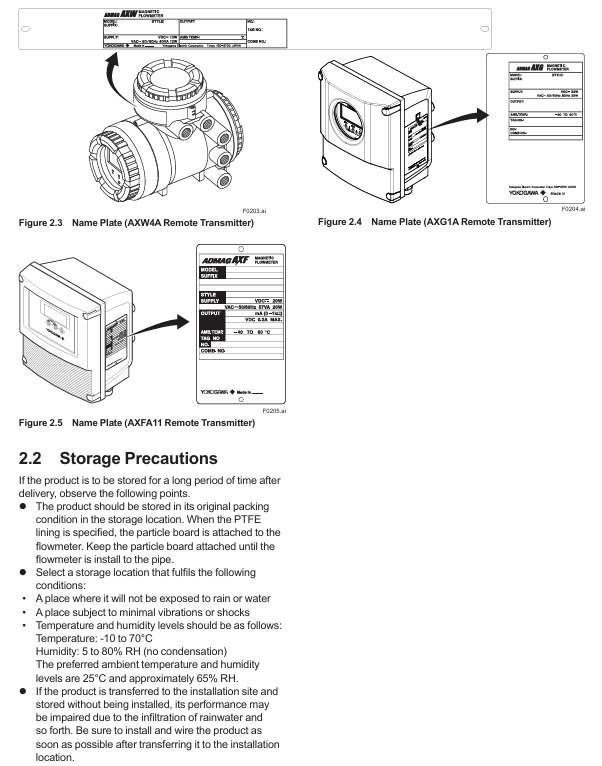
Model and specification confirmation: Verify the model, serial number, instrument coefficient, fluid specifications, etc. through the equipment nameplate (as shown in Figure 2.1-2.5) to ensure consistency with the order; The nameplate information can also be viewed through the parameter menu (refer to the corresponding communication type manual).
2. Storage requirements
Packaging: The original packaging should be retained for long-term storage, and the PTFE lining model should retain the accompanying particle board until it is removed before installation.
Environment: Storage temperature -10~70 ℃, humidity 5~80% RH (non condensing), preferably 25 ℃, 65% RH environment; Avoid exposure to rain, vibration, and impact, and install as soon as possible after transportation to the installation site to prevent rainwater infiltration.
Installation process and requirements
1. Preparation before installation: pipeline design principles
Requirements for straight pipe section: It must meet JIS B 7554 standard. The length of the upstream straight pipe section should be 5D~10D (D is the sensor diameter) depending on the upstream pipe fittings, and 2D~3D (as shown in Figure 3.1.1) downstream to avoid uneven flow distribution affecting measurement.
Fluid conditions: The pipeline should always be filled with liquid (when installed vertically, the fluid flows from bottom to top) to avoid bubbles (valves should be installed downstream first to prevent negative pressure from generating bubbles); The injection point of chemical agents should be downstream of the flow meter. If it is necessary to reserve a straight pipe section of more than 50D upstream to ensure uniform mixing.
Anti interference: Keep away from power equipment such as motors and transformers; The distance between multiple electromagnetic flow meters should be ≥ 5D (taking the larger diameter D); To avoid pipeline misalignment and tilting (as shown in Figure 3.2.2), new pipelines need to be flushed to remove foreign objects such as welding slag and sawdust.
2. Installation of sensors and transmitters
(1) Integrated/remote sensor installation
Classification installation:
**Wafer type (25-200mm) * *: It is necessary to use a centering device to ensure concentricity, and the bolt torque should be based on the flange grade (such as JIS 10K, ASME Class 150) according to Table 3.3.2; 50mm/2-inch submersible JIS 20K wafer requires special double headed bolts.
Flange type (25-450mm): The gasket needs to be provided by the user (except in special circumstances), and the use of wrapped gaskets is prohibited; Attention should be paid to avoiding negative pressure for PTFE lining models, and uneven force on the lining should be prevented during installation (refer to Table 3.3.6-3.3.7 for torque values).
Grounding requirements: The protective grounding resistance should be ≤ 100 Ω (Class D), and the lightning protection requirement should be ≤ 10 Ω (Class C); Metal pipelines should be connected to sensor flanges through grounding rings or grounding wires first, while plastic pipelines must use grounding rings.
(2) Remote transmitter installation
Installation location: Avoid direct sunlight and ensure that the environment meets temperature/humidity requirements; AXW4A can be installed vertically/horizontally on 2-inch pipes, while AXG1A/AXFA11G supports surface mounting, 2-inch pipe mounting, and panel mounting (must meet load-bearing requirements: AXG1A 3.5kg, AXFA11G 3.4kg, and the bracket needs to withstand 4 times the weight).
Direction adjustment: The cable entry direction (non submersible/DHC type) can be rotated by -90 °/+90 °/+180 °, and the display screen direction can be rotated clockwise by 90 ° (the cover plate needs to be removed, pay attention to protecting the threads and O-ring).
3. Gasket selection and size
Core requirement: The inner and outer diameters of the gasket must not extend into the pipeline to avoid fluid leakage or affect measurement; Different linings (such as natural hard rubber, PTFE, polyurethane rubber) need to be matched with corresponding hardness gaskets (such as non asbestos gaskets, PTFE coated gaskets), with thickness reference to Tables 3.3.1/3.3.4.
Size inquiry: The user's pipeline gasket size should refer to Table 3.3.8, specifying the effective sealing inner diameter (ø A) and recommended gasket inner diameter (ø C/ø D) corresponding to different linings and connection types (wafer/flange).
Wiring specifications
1. Preparation before wiring
Cable requirements:
Excitation/power/IO cables: JIS C 3401 control cables and JIS C 3312 power cables are recommended, with a wire diameter of 0.5~2.5mm ² (single strand)/0.5~1.5mm ² (multiple strands), and the outer diameter needs to match the cable sealing sleeve (such as waterproof sealing sleeve compatible with 7.5~12mm).
Special signal cable (AX01C): Double shielded structure, with a maximum length of 200m when paired with AXG1A/AXFA11 and 100m when paired with AXW4A. Cutting or splicing is prohibited, and excess length must be cut off.
Protective measures: When the ambient temperature is above 50 ℃, cables with a temperature resistance of 70 ℃ or above are required; Power and signal cables need to be separately threaded through steel conduits (excluding 24V power supply and 4-core cables); Explosion proof wiring must comply with the corresponding explosion-proof standards.
2. Wiring operation
Power wiring: DC power supply should pay attention to the positive and negative poles (L/+connected to the positive pole, N/- connected to the negative pole), and 24V models should not be connected to 100-240V power supply; 15A external switch/circuit breaker needs to be installed and labeled as "power-off equipment".
Grounding Wiring: The protective grounding wire requires a 600V ethylene insulated cable, and the terminals require circular crimping terminals (M4 screws) with insulation covers to ensure reliable connection; Remote type requires separate grounding sensors and transmitters.
Cable entrance sealing: Unused entrances need to be sealed with dedicated plugs, waterproof sealing sleeves need to be evenly tightened (to avoid damaging the cable due to over tightening), and vertical conduits need to be equipped with drainage valves at the low end and regularly drained.
3. Communication and IO wiring
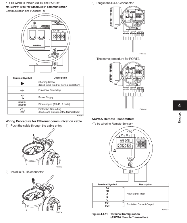
Communication protocol wiring: Modbus requires 3-core shielded wire (AWG24 or above), FOUNDATION Fieldbus/PROFIBUS PA requires Type A cable, EtherNet/IP requires CAT5e or above shielded twisted pair (without protective cover).
IO signal wiring: current output (4-20mA), pulse output (maximum 10000 pulses/second), status input (no voltage contacts), etc. need to be wired according to the terminal configuration table (such as 4.4.4/4.5.2) to ensure galvanic isolation (input/output/power circuits are isolated from each other).
Basic operations and parameter settings
1. Operation method
Display screen operation: Operated through three infrared (IR) buttons ([SET], [SHIFT], [▼]), supporting parameter viewing/modification, zero point adjustment, etc; The default display language is English, which can be switched through "Device setup ► Language" (supports multiple languages such as Chinese, French, German, etc., depending on the display code).
Operation level: divided into three levels: Operator (no password required, only basic display settings), Maintenance (maintenance personnel, password required, including zero adjustment), Specialist (expert, password required, full parameter settings), default password "0000".
2. Key operational procedures
(1) Mode switching: Display mode → Set mode
Long press [SET] for a few seconds, touch [FFT]+[INC];
Select "Yes" with [INC], double-click [SET] to confirm;
Select the operation level, enter the corresponding password (Maintenance/Specialist requires password), and enter the "Device setup" menu.
(2) Example of Parameter Setting
Flow unit setting (optional parameter): Path "Device setup ► Detailed setup ► Pro var ► Volume ► Unit/Time Unit". If setting "l/min", select "l (lite)" (physical unit) and "/min" (time unit) respectively.
Flow range setting (numerical parameter): Path "Device setup ► Detailed setup ► Pro var ► Volume ► Span", the unit needs to be set first, and the range value will be automatically converted with the unit.
Tag number setting (alphanumeric parameter): Path "Device setup ► Detailed setup ► Device info ► Order info ► Tag No.", maximum input of 8 ASCII characters.
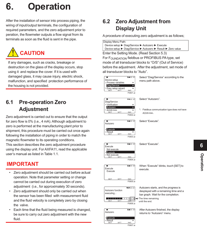
(3) Pre operation Zero Adjustment
Prerequisite: The sensor is filled with fluid and the flow rate is 0 (with the valve closed). For the FILDVUE/PROFIBUS PA type, all sensor blocks must first be set to "O/S" mode.
Operation path: "Device setup ► Diag/Service ► Autozero ► Execute". Double click [SET] to start, taking about 30 seconds. After completion, check the "Result ► Zero value" to confirm the result (exceeding 10cm/s will trigger a warning "092: AZ warning").
3. Use of configuration tools
BRAN/HART: Connected through BT200 or FieldMate, it needs to be parallel in a 4-20mA circuit, with load resistance ≥ 250 Ω/230 Ω respectively.
Modbus/FOUNDATION Fieldbus/PROFIBUS PA: Corresponding DTM (such as AXW4A Modbus DTM 1.1.4.0 or above) is required, and FieldMate needs to be upgraded to the corresponding version.
EtherNet/IP: Supports web configuration (requires IE8+/Chrome/Edge browser), requires installation of corresponding EDS file (supplier ID 250, product code 206).
Operation and maintenance
1. Hardware switch settings
Burnout switch: When the CPU fails, the current output direction defaults to a high value (>21.6mA), and when C1/C2 is installed, a low value (<2.4mA) is set.
Write Protect: To prevent parameter tampering, rewriting is prohibited when the hardware switch is set to "ON" (in conjunction with software write protection).
Address switch: Modbus (1-127), PROFIBUS PA (0-126), EtherNet/IP (set IP segment 4) need to be set through 8-bit dialing, and priority is controlled by the SW3-1 switch.
Terminal resistor switch (SW2): A 150 Ω terminal resistor (SW2-1/SW2-2 both "ON") is required at both ends of the Modbus bus.
2. Correction factor setting (for specific flanges)
Applicable scenarios: When using 40-125mm wafer type and specific linings (such as polyurethane rubber U, natural hard rubber H) with carbon steel flanges, a correction factor (CFL/CFH: double-sided carbon steel) needs to be set; CF1L/CF1H: single-sided carbon steel), the coefficient is marked on the nameplate or on the Yokogawa official website for reference.
Set path: such as the display screen "Device setup ► Detailed setup ► Sensors ► Low MF/High MF", Modbus address 40321 (Low MF)/40323 (High MF).
3. Fault handling
Chapter 7 of the document provides a detailed list of four types of faults: system alarms (equipment failures, such as "010: Main CPU FAIL" requiring contact with the service center), process alarms (process issues, such as "051: Empty detect" requiring fluid filling), set alarms (parameter errors, such as "060: Span cfg ERR" requiring range adjustment), and warnings (such as "087: Adhesion lv 3" requiring electrode cleaning). Each fault includes NE107 status (F/C/S/M/N), description, and countermeasures. Examples are as follows:
NE107 status error code/information reason countermeasures
F 010: Main CPU FAIL Mainboard CPU failure Contact Yokogawa Service Center
S 051: Empty detect sensor fills the pipeline with liquid through the empty tube
C 060: Span cfg ERR flow range setting error (requires 0.05<Span<16m/s) Check and correct range parameters
M 087: Adhesion lv 3 electrode adhesion insulation (resistance exceeding level 3). It is recommended to clean the electrode
- YOKOGAWA
- Reliance
- ADVANCED
- SEW
- ProSoft
- WATLOW
- Kongsberg
- FANUC
- VSD
- DCS
- PLC
- man-machine
- Covid-19
- Energy and Gender
- Energy Access
- Renewable Integration
- Energy Subsidies
- Energy and Water
- Net zero emission
- Energy Security
- Critical Minerals
- A-B
- petroleum
- Mine scale
- Sewage treatment
- cement
- architecture
- Industrial information
- New energy
- Automobile market
- electricity
- Construction site
- HIMA
- ABB
- Rockwell
- Schneider Modicon
- Siemens
- xYCOM
- Yaskawa
- Woodward
- BOSCH Rexroth
- MOOG
- General Electric
- American NI
- Rolls-Royce
- CTI
- Honeywell
- EMERSON
- MAN
- GE
- TRICONEX
- Control Wave
- ALSTOM
- AMAT
- STUDER
- KONGSBERG
- MOTOROLA
- DANAHER MOTION
- Bentley
- Galil
- EATON
- MOLEX
- Triconex
- DEIF
- B&W
- ZYGO
- Aerotech
- DANFOSS
- KOLLMORGEN
- Beijer
- Endress+Hauser
- schneider
- Foxboro
- KB
- REXROTH
- YAMAHA
- Johnson
- Westinghouse
- WAGO
- TOSHIBA
- TEKTRONIX
- BENDER
- BMCM
- SMC
- HITACHI
- HIRSCHMANN
- XP POWER
- Baldor
- Meggitt
- SHINKAWA
- Other Brands
- UniOP
- KUKA
- IBA
- Beckhoff
-
LTI SC52.0040.0012.0000.0 - Servo Drive
-
Lti SC52.0040.0012.0000.0 - Servo Drive
-
Milton Industries LTI Tool By Milton LT1240 - 1/2" Drive Lugnut Remover
-
LTi Drives SO84.200.P030.0000.0-W - Servo Spindle Drive
-
LTI DRIVES LSP08-035-320-30-B0R1PY170 - Servo Motor
-
LTI DRIVES SE84.200.SC00.0001.0-W - Servo Drive
-
Lust CDE34.005.W2.2 - Lti Drives Controller
-
LTi SO84.012.0030.0011.2 - ServoOne Servo Drive
-
LTi Drives SO CM-P.0010.11.00.0 - Servo Drive Controller
-
LTi CDE34.017.W3.0 - Servo Drive
-
LTI Drives CDB32.004, C2.0,SH - Positioning Controller
-
LUST CM-CAN1 - LTi DRIVES Communication Module
-
LTi SO84.012.1030.0000.2 - Servo Drive
-
LTI MOOG CDE54.044 - PITCHMASTER FREQUENCY CONVERTER 181-01019
-
MOOG LTI 181-01019 CDE54.044 - PITCHMASTER FREQUENCY CONVERTER
-
Lust LTi Drives CDE34.010,D2.0 - Servo Drive Controller
-
LTI SO84.032.0003.0101.2 - Servo Drive
-
Seagate 9CC132-302 Harris LTI-CS IRT-34-0021-01 - Hard Drive 160GB
-
LTI SO84.032.0003.0001.2 - Servo Drive
-
LTI SO24.007.0070.0000.1 - SERVO CONTROLLER
-
LTi drive CDA32.003.C3.0.H05-01.PC1 - Servo Drive
-
LTI SO84.016.0030.0000.2 - SERVO CONTROLLER
-
LUST LTI CD A34.008,W1.4, BR - SERVO DRIVE
-
MOOG LTI 181-01019 CDE54.044 - PITCHMASTER FREQUENCY CONVERTER
-
LTI MOOG 181-01019 - PITCH Master Servo Drive CDE54.044
-
LTI SERVO ONE SO84.045.0030.0001.2-W - Drive
-
LUST LTi SO84.032.0040.0000.2 - SERVO ONE DRIVE
-
LTi Drives LSH-074-2-30-3 20/T1,G6.1M - SERVO MOTOR
-
LTI SO84.016.0000.0101.2 - servo drive
-
LTI SA54.0550.0033.0000.0 - Servo Drive
-
LTI SA54.0550.0033.0000.0 - Servo Drive
-
LTI LT 4850 - 3/8" Drive 3-Pc Twist Socket Transmission Drain Plug Removal System
-
LTI Tools LT4400-30 Lock Technology - 3/4" Twist Socket 1/2" Drive Lugnut Remover
-
LTI Tools LT-1400C - 1/2 Drive Wheel Torque Extension Tool
-
LTI Tools LT1250 - 1/2" Drive Dual Sided Socket Lug Nut Remover Tool
-
LTI SO84.032.0003.0101.2 - Servo Drive
-
LTI MOOG 181-01019 - PITCH Master Servo Drive CDE54.044
-
MOOG LTI 181-01019 CDE54.044 - PITCHMASTER FREQUENCY CONVERTER
-
MOOG LTI 181-01019 CDE54.044 - PITCHMASTER FREQUENCY CONVERTER
-
MOOG LTI 181-01019 CDE54.044 - PITCHMASTER FREQUENCY CONVERTER
-
LTI SA54.0550.0033.0000.0 - Servo Drive
-
LTI Tools LT-4800 - 7 Piece Twist Socket 3/8" Drive Oil Drain Plug Removal Set
-
LTI SA54.0550.0033.0000.0 - Servo Drive
-
LTI Drive SO24.007.00300000.0 - Servo Drive
-
LTI TOOLS LTI 1400-I - Drive Wheel Torque Extension
-
LTI Tools LT4400-3 - 3/4" 19mm Twist Socket 1/2" Drive Lugnut
-
LTI TOOLS LTI 1400-BB - Drive Wheel Torque Extension
-
LTI SO84.032.0003.0101.2 - Servo Drive
-
LTI Tools LT-4512 - 3/8" Drive 12mm Twist Socket
-
LTI MOTION Luster SO84.032.0003.0001.2 - Servo Drive
-
LTI Tool By Milton LT1600P - 1" Drive Torx Stick
-
LTI Lust VF1424L,HF,OP2,S56 - Variable Frequency Drive
-
LUST CDA32.004,C1.4,H08,B0 - SERVO DFRIVE CM-CAN1 Module
-
LTI SO84.045.0002.0001.2-W - Drive
-
LTI Lust VF1404M,C9,PT1,BR1 - Inverter Type VF1404M
-
LTI SA54.0550.0033.0000.0 - Servo Drive
-
LTI Tools LT-1400C - 1/2" Drive Wheel Torque Extension
-
Lust LTI DRiVES CDA32.006, C3.0, H09 - Variateur De Fr茅quence Frequency Inverter
-
LTI MOOG CDE54.044 - PITCH master SERVO DRIVE
-
LTI MOOG CDE54.044 - PITCH master SERVO DRIVE
-
LTI SO84.143.0020.0101.2-W - servo drive
-
LTI MOTION SC34.0200.0011.0000.0 - Servo drives
-
LTI SO84.032.0003.0001.2 - Servo Drive
-
LTI DRIVES GmbH MS100 - Assembly Set Mounting Kit
-
LTI SO84.032.0003.0001.2 - Servo Drive
-
LTI SO84.032.0003.0001.2 - Servo Drive
-
LTI MOTION SO84.032.0003.0101.2 - servo drive
-
LTI SO84.032.0003.0101.2 - Servo Drive
-
LTI MOOG CDE54.044 - PITCH master SERVO DRIVE
-
LTI MOTION CDE32.004.C2.4 - Servo drives
-
LTI CDD34.032锛學x.x锛孊R锛孭C1 - Servo Drive
-
Lust LTI DRiVES CDA32.006, C3.0, H09 - Inversor De Frecuencia Frequency Inverter
-
Lust SO84.008.0030.1000.0 - Servo One LTi Drive
-
LTI MOTION SO84.032.0003.0101.2 - Servo drives
-
LUST LTi CDA32.004,C1.4 - SERVO DRIVE
-
LTI MOOG CDE54.044 - PITCH Master SERVO DRIVE
-
LTI KEBA CDB32.004 C2.7, SH - PN: 08673530 Frequency Inverter
-
LTI Tools LT-1400C - 1/2" Drive Wheel Torque Extension
-
LTI LT1400-E - 1/2" Drive Wheel Torque Extension
-
LTI MOOG 181-01019 - PITCH master SERVO DRIVE CDE54.044
-
LTI LSN-097-0510-30-560/T1 - Actuator Motor
-
LTI Tools LT 4800 - 7 Piece 3/8" Drive Twist Socket Oil Drain Plug Removal System
-
LTI DRIVES GmbH MS100 - MONTAGESET Assembly Set Mounting Kit
-
Lti SC52.0040.0012.0000.0 - Servo Drive
-
LTI DRIVES GmbH MS100 - Juego De Montaje Assembly Set Mounting Kit
-
LTi DSM4-14.2-21R83-200 - Drives servomoteur Servo Motor
-
MOOG CDE 54.044.GDA - Pitch Master Industrielle Turbine Lti Drive
-
LTI SO24.004.0030.1000.0 - Servo Drive Controller
-
Lti MOOG CDE54.044 - Pitch Master Servo Drive
-
Lust LTI DRiVES CDA32.006, C3.0, H09 - Inverter
-
LTI MOTION GMBH CDB34.006,W3.0,PC1,H39 - Frequency inverter
-
LTI SO84.032.0003.0001.2 - Servo Drive
-
MOOG CDE 54.044.D - Pitch Master Industrielle Turbine Lti Drive
-
LTI TOOLS LT-1460 - 1/2" DRIVE WHEEL TORQUE EXTENSION KIT 5 PIECE SET
-
Lust Cdb32.003, C2.4 - Lti Drives Servoregulador Frecuencia Servo Controller Inverter
-
Lust LTI DRIVES CDA32.006, C3.0, H09 - Frequency Inverter
-
Lust Lti SO82.004.0030.0000.2 - Servo Drive
-
LTI MOTION SC34.0200.0011.0000.0-SL - Servo drives
-
LTI MOTION SA54.0075.0033.0000.0 - Servo drives
-
LTI MOTION SC32.0075.1011.0000.0 - Servo drives
-
LTI Servo-One Junior SO22.006.0080.1000.0 - Servo Controller Servoregler
-
LUST CDA32.004, C1.4, H08, B0 - Servo Drive & LTI CM-CAN1 Module
-
LTI DRIVES LSP08-035-320-30-B0R1PY170 - Servo Motor
-
LUST LTI CDA32.004,C1.4.H08.B0 - SERVO CONTROLLER DRIVES
-
LUST LTi DRiVES CDS44.072LC1.2 - Servo Drive
-
Lti Servo-One Junior SO22.006.0082.1000.0 - Servo Controller Servoregler
-
LUST CDA32.008,C2.0,HF - Lti DRIVES Spindle Drive Inverter
-
LTI SO22.003.0082.0000.0 - Servo Drives One junior Servo Controller Servoregler
-
Lust Lti Drives CM-CAN1 - Communication Module
-
LUST Lti Drives Vf1202s, G8, I6 - Frequency Inverter Drive
-
LTI DRIVES BR-090.03.540.UR.H38 - Bremswiderstand Brake Resistor
-
LTi DRIVES PM-E40.2DRA054P - Wind Turbine Pitch Control Inverter
-
LTi Drives GmbH br-110.01.540-UR - Brake Resistor
-
LTI Drives LSN-097-0960-30-0560/T1,S4,B - Servo Motor
-
LUST CDA34.006.C2.0 - LTI Drives Servoregler
-
LUST LTI DRIVES SERVO ONE JUNIOR SO24.002.0020.0000.1 - Servo Drive Controller
-
LTI MOTION SO84.032.0003.0001.2 - Servo drives
-
LTI DDTD750V2-120 - IBOP ACTUATOR CYLINDER FOR TOP DRIVE
-
LTI CDE32.004, C2.4 - SERVO DRIVE
-
LUST LTI DRIVES CDD34.017 W3.4PC1 - Servo Drive Controller
-
LTI CDA3208,C3,0,HF - AC SERVO DRIVE
-
LUST LTI DRIVES LSH-074-3-30-560/T1,G6.1S - SERVO MOTOR
-
LUST Lti CDB32.004.C2.4.SH - AC Servo Drive
-
LTi CDA32.006, C3.0, H09 - Servo Drive
-
LTI SO22.003.0010.0000.0 - Servo Drive Servo one junior Servoregler Controller
-
LTi Drives DSM4-14.2-21R83-200 - Servo Motor
-
LUST Lti Drives Lsh-097-1-30-560/T1, 1R - Servomotor
-
LTI 1237 - 7 Piece 1/2" Drive Flip Socket Set

K-JIANG

Add: Jimei North Road, Jimei District, Xiamen, Fujian, China
Tell:+86-15305925923