
K-WANG
+086-15305925923
Service expert in industrial control field!


Product
Article
NameDescriptionContent
Adequate Inventory, Timely Service
pursuit of excellence


Ship control system
Equipment control system
Power monitoring system
Current position:
新闻动态
newS
Brand
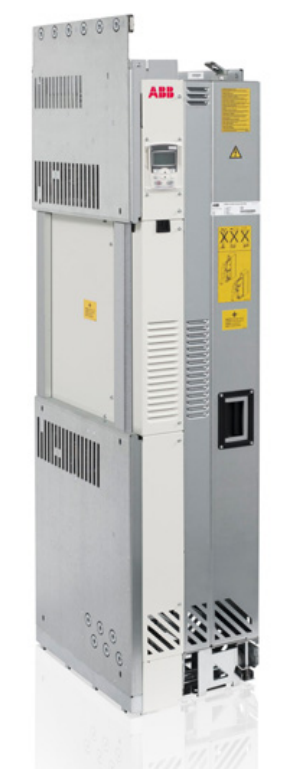
ABB ACS850-04 drive modules
ABB ACS850-04 drive modules
ABB ACS850-04 drive modules
What this chapter contains
This chapter contains the safety instructions which you must follow when installing,
operating and servicing the drive. If ignored, physical injury or death may follow, or
damage may occur to the drive, motor or driven equipment. Read the safety
instructions before you work on the unit.
Use of warnings
Warnings caution you about conditions which can result in serious injury or death
and/or damage to the equipment and advise on how to avoid the danger. The
following warning symbols are used in this manual:
Electricity warning warns of hazards from electricity which can cause
physical injury and/or damage to the equipment.
General warning warns about conditions, other than those caused by
electricity which can result in physical injury and/or damage to the
equipment.
Electrostatic sensitive devices warning warns of electrostatic
discharge which can damage the equipment.
Hot surface warning warns of component surfaces that may become
hot enough to cause burns if touched.
Electrical safety
These warnings are intended for all who work on the drive, motor cable or motor.
WARNING! Ignoring the following instructions can cause physical injury or death, or
damage to the equipment:
• Only qualified electricians are allowed to install and maintain the drive.
• Never work on the drive, motor cable or motor when main power is applied.
After disconnecting the input power, always wait for 5 min to let the intermediate
circuit capacitors discharge before you start working on the drive, motor or
motor cable.
Always ensure by measuring with a multimeter (impedance at least 1 Mohm)
that:
1. voltage between drive input phases U1, V1 and W1 and the frame is close to
0 V.
2. voltage between terminals UDC+ and UDC- and the frame is close to 0 V.
• Do not work on the control cables when power is applied to the drive or to the
external control circuits. Externally supplied control circuits may cause
dangerous voltages inside the drive even when the main power on the drive is
switched off.
• Do not make any insulation or voltage withstand tests on the drive or drive
modules.
Note:
• The motor cable terminals on the drive are at a dangerously high voltage when
the input power is on, regardless of whether the motor is running or not.
• The brake control terminals (UDC+, UDC-, R+ and R- terminals) carry a
dangerous DC voltage (over 500 V).
• Depending on the external wiring, dangerous voltages (115 V, 220 V or 230 V)
may be present on the terminals of relay outputs (X2) or Safe torque off (X6).
• The Safe torque off function does not remove the voltage from the main and
auxiliary circuits
Grounding
These instructions are intended for all who are responsible for the grounding of the
drive.
WARNING! Ignoring the following instructions can cause physical injury, death,
increased electromagnetic interference and equipment malfunction:
• Ground the drive, motor and adjoining equipment to ensure personnel safety in
all circumstances, and to reduce electromagnetic emission and interference.
• Make sure that grounding conductors are adequately sized as required by
safety regulations.
• In a multiple-drive installation, connect each drive separately to protective
earth (PE).
• Where EMC emissions must be minimized, make a 360° high frequency
grounding of cable entries at the cabinet lead-through in order to suppress
electromagnetic disturbances. In addition, connect the cable shields to
protective earth (PE) in order to meet safety regulations.
Note:
• Power cable shields are suitable for equipment grounding conductors only
when adequately sized to meet safety regulations.
• As the normal leakage current of the drive is higher than 3.5 mA AC or 10 mA
DC, a fixed protective earth connection is required by EN 61800-5-1, 4.3.5.5.2.
Permanent magnet motor drives
These are additional warnings concerning permanent magnet motor drives.
WARNING! Ignoring the instructions can cause physical injury or death, or damage
to the equipment.
• Do not work on the drive when the permanent magnet motor is rotating. Also,
when the supply power is switched off and the drive is stopped, a rotating
permanent magnet motor feeds power to the intermediate circuit of the drive and
the supply connections become live.
Before installation and maintenance work on the drive:
• Stop the motor.
• Ensure that there is no voltage on the drive power terminals according to step 1 or
2, or if possible, according to the both steps.
1. Disconnect the motor from the drive with a safety switch or by other means.
Measure that there is no voltage present on the drive input, output or DC
terminals (U1, V1, W1, U2, V2, W2, UDC+, UDC-).
2. Ensure that the motor cannot rotate during work. Make sure that no other system,
like hydraulic crawling drives, is able to rotate the motor directly or through any
mechanical connection like felt, nip, rope, etc. Measure that there is no voltage
present on the drive input, output or DC terminals (U1, V1, W1, U2, V2, W2,
UDC+, UDC-). Ground the drive output terminals temporarily by connecting them
together as well as to the PE.
These instructions are intended for all who install and service the drive.
WARNING! Ignoring the following instructions can cause physical injury or death,
or damage to the equipment:
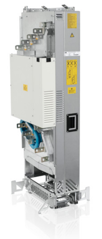
• - Lift the drive module using the lifting lugs attached to the top and base of the
unit.
- Handle the drive module carefully. Make sure that the module does not fall
down when moving it on the floor and during installation and maintenance
work: Open the support legs by pressing each leg a little down (1, 2) and
turning it aside. When ever possible secure the module also with chains.
- Do not tilt the drive module (A). It is heavy (over 160 kg [350 lb]) and its
center of gravity is high. The module will overturn from a sideways tilt of 5
degrees. Do not leave the module unattended on a sloping floor.
Push the drive module into the cabinet and pull it from the cabinet carefully
preferably with help from another person as shown below. Keep a constant
pressure with one foot on the base of the module to prevent the module from
falling on its back. Use safety shoes with metal toe cap to avoid foot injury.
Do not use the ramp with plinth heights which exceed the maximum height
marked on the ramp next to the fastening screw. (The maximum plinth height
is 50 mm when the telescopic ramp is shortest and 150 mm when the ramp is
longest.) Tighten the two fastening bolts of the ramp carefully.
• Beware of hot surfaces. Some parts, such as heatsinks of power
semiconductors, remain hot for a while after disconnection of the electrical
supply.
• Make sure that dust from borings and grindings does not enter the drive when
installing. Electrically conductive dust inside the unit may cause damage or
malfunctioning.
• Ensure sufficient cooling.
• Do not fasten the drive by riveting or welding.
WARNING! Ignoring the following instructions can cause equipment malfunction
and damage to the fiber optic cables:
• Handle the fiber optic cables with care. When unplugging optic cables, always
grab the connector, not the cable itself. Do not touch the ends of the fibers with
bare hands as the fiber is extremely sensitive to dirt. The minimum allowed
bend radius is 35 mm (1.4 in.).
Printed circuit boards
WARNING! lgnoring the following instructions can cause damage to the printed
circuit boards:
Wear a grounding wrist band when handling the boards. Do not touch the
boards unnecessarily. The printed circuit boards contain components sensitive
to electrostatic discharge.
Safe start-up and operation
General safety
These warnings are intended for all who plan the operation of the drive or operate
the drive.
WARNING! Ignoring the following instructions can cause physical injury or death,
or damage to the equipment:
Before adjusting the drive and putting it into service, make sure that the motor
and all driven equipment are suitable for operation throughout the speed range
provided by the drive. The drive can be adjusted to operate the motor at
speeds above and below the speed provided by connecting the motor directly
to the power line.
Do not activate any automatic fault reset functions of the drive control program
if dangerous situations can occur. When activated, these functions will reset
the drive and resume operation after a fault.
Do not control the motor with an AC contactor or disconnecting device;
instead, use the control panel keysand ⑦, or commands via the l/O
board of the drive. The maximum allowed number ofcharging cycles of the DC
capacitors, ie, power-ups by applying power, is five in ten minutes.
Note:
●If an external source for start command is selected and it is ON, the drive will
start immediately after an input voltage break or fault reset unless the drive is
configured for 3-wire (a pulse) start/stop.
.When the control location is not set to local, the stop key on the control panel
will not stop the drive.
Permanent magnet motor drives
WARNING! Do not run the motor over the rated speed. Motor overspeed leads to
overvoltage which may damage orexplode the capacitors in the intermediate circuit
of the drive.
- YOKOGAWA
- Reliance
- ADVANCED
- SEW
- ProSoft
- WATLOW
- Kongsberg
- FANUC
- VSD
- DCS
- PLC
- man-machine
- Covid-19
- Energy and Gender
- Energy Access
- Renewable Integration
- Energy Subsidies
- Energy and Water
- Net zero emission
- Energy Security
- Critical Minerals
- A-B
- petroleum
- Mine scale
- Sewage treatment
- cement
- architecture
- Industrial information
- New energy
- Automobile market
- electricity
- Construction site
- HIMA
- ABB
- Rockwell
- Schneider Modicon
- Siemens
- xYCOM
- Yaskawa
- Woodward
- BOSCH Rexroth
- MOOG
- General Electric
- American NI
- Rolls-Royce
- CTI
- Honeywell
- EMERSON
- MAN
- GE
- TRICONEX
- Control Wave
- ALSTOM
- AMAT
- STUDER
- KONGSBERG
- MOTOROLA
- DANAHER MOTION
- Bentley
- Galil
- EATON
- MOLEX
- Triconex
- DEIF
- B&W
- ZYGO
- Aerotech
- DANFOSS
- KOLLMORGEN
- Beijer
- Endress+Hauser
- schneider
- Foxboro
- KB
- REXROTH
- YAMAHA
- Johnson
- Westinghouse
- WAGO
- TOSHIBA
- TEKTRONIX
- BENDER
- BMCM
- SMC
- HITACHI
- HIRSCHMANN
- XP POWER
- Baldor
- Meggitt
- SHINKAWA
- Other Brands
- UniOP
- KUKA
- IBA
- Beckhoff
- ADLINK
51
-
Beckhoff CX1100-0910 - Power Supply Module
-
Beckhoff C5210-0010 - Communication Module C5210
-
BECKHOFF KL1352 - Bus Terminal SET OF 2 FREE FAST SHIP
-
Beckhoff EL3058 - 8 x analog input single ended 4...20mA 85惟 shunt 12bit
-
Beckoff CX1100-0920 - UPS Module 24VDC (US SELLER) * *
-
BECKHOFF C6920-0000 - C69200000 PLC Moudule
-
Beckhoff CX5120-0115 - CPU controller module CX5120-0115
-
Unknown 15F5C1E-Y50A - Of Frequency Converters
-
Beckhoff AX5118-0000-0200 - Servo Drive HTP0
-
BECKHOFF AX5106-0000-0200 - Servo Drive
-
Beckhoff CX5240-0175 - Module (free) #U2327D YG
-
Beckhoff CP6607-0001-0000 - Compact PC Panel Economy Installation Operator 5,7 "
-
Beckhoff EP3744-0041 - 2022 EP37440041 Module
-
Beckhoff CP6209-0001-0020 - 6.5" PC Touch Screen Control Panel 24VDC
-
Beckhoff CX9020-0111 - /U900 +8x+2xEL3121+1x EL9410+3xEL1008+1x EL2008 Set
-
Beckhoff C6525-1030-0050 - Industrial PC
-
Beckoff CX1100-0920 - UPS Module 24VDC (US SELLER)
-
Beckhoff CX5010-0120 - CX5010 Processor Intel Atom Z510 B24
-
Siemens 6FC5203-0AF04-1BA1 - Operation Panel
-
Beckhoff CX5230-0175 - / 000029724 Embedded PC / Industrial PC on Rail
-
Beckhoff CP3916-0000 - industrielles Anzeige- und Bedienterminal
-
BECKHOFF CX1500-M310 - CX1000-N000 CX1000-0011 CX1000-C00L CX1100-0002 PLC Module
-
Beckhoff EL1872 - 16-channel digital input terminal
-
BECKHOFF EP2318-0001 - module
-
Beckhoff CX9020-0110 - Basic CPU Module
-
Beckhoff EL2564 - EtherCAT Terminal, 4-channel LED output, 5鈥?8VDC, 4A, RGBW
-
Beckhoff CX5130-0155 - /000105637 Automation Embedded PC
-
B&R 400 - Power Control Panel Rev D0 24 VDC
-
Beckhoff CX2020-0155 - module
-
Beckhoff CX9020-0115 - PLC Module
-
BECKHOFF EL6695 - PLC EL 6695
-
BECKHOFF EL7047 - PLC Modules
-
Beckhoff CX1000-0012 - Control HW 2.2 + CX1500-M310 + CX1000-C00L + CX1100-0002+
-
Beckhoff C6920-1039-0030 - control cabinet industrial PC CPU Celeron 1.90 GHz, 2 cores
-
BECKHOFF CX1100-0910 - PLC Module#
-
Beckhoff IL2301-B318-0000 - Coupler Box 4 Channel Digital Input |
-
Beckhoff CX7080 - Module
-
Beckhoff C6930-0060 - Industrial PC
-
Beckhoff CP7902-1060-0000 - Touchscreen 15 " CP7902
-
beckhoff CX9020-0111 - Controller module or UPS
-
Beckhoff CX8091 - PLC Module CX8091
-
Beckhoff C6640-1008-0030 - Control Cabinet Industrial PC
-
BECKHOFF CX1100-0920 - module
-
Beckhoff C9900-M921 - see pictures
-
BECKHOFF CP6829-0001-0000 - Touch Panel
-
BECKHOFF C6930-0060 - Industrial Computer
-
BECKHOFF CX8050 - PLC module
-
Beckhoff CP6202-0021-0020 - Touch Screen #
-
BECKHOFF AM3031-0C20-0000 - SERVO MOTOR
-
Unknown BCH1302N11A1C - Servo motor
-
Beckhoff EL2502 - 2-channel pulse width output terminal
-
Beckhoff EL6731 - Profibus Master / *Rev: 0025
-
Beckhoff CP3918-0010 - Control Panel
-
BECKHOFF CP2915-0010 - [24 MONTH WARRANTY] Control Panel
-
Beckhoff AX5203-0000-0202 - Servo Drive
-
Schneider TSXDSY64T2K - PLC OUTPUT MODULE
-
Beckhoff EP4174-0002 - Module-
-
Beckhoff IL2302-B318-0000 - Profibus Box
-
Beckhoff CP6709-0001-0000 - Touchpanel
-
BECKHOFF CX2030-0123 - Controller
-
Beckhoff CX9020-0111 - Processor Module
-
Beckhoff CX1020-0000 - CX Basic CPU Module
-
Beckhoff AX2003-AS - Servo Drive HTP0
-
Beckhoff C6240-1052-0040 - 4-086-06-3073 Industrial Computer CB1052-0003
-
Beckhoff EL1918 - 8 xTwinSAFE Input
-
Beckhoff AM8072-0R20-0000 - Servomotor
-
BECKHOFF AM8021-1B21-0000 - servo motor #T882 YS
-
Beckhoff EL6224 - 4 X Terminal IO-LINK
-
Beckhoff CX5140-0135 - embedded PC with Intel Atom processor 4 GB HW 3.6
-
Beckhoff CP7201-1000-0000 - Panel PC #
-
Beckhoff CX5130-0121 - Embedded-PC 4GB CPU Module HW 2.5 Industrial PC
-
Beckhoff AM8022-0D41-1002 - Servomotor
-
BECKHOFF CX2030-0130 - Module
-
BECKHOFF EL1872 - 16-channel digital input terminal
-
Unknown GXMMW.A203P33 - 1pc encoder
-
Beckhoff EL6631-0000 - EtherCAT Terminal 2-Port EL 6631
-
BECKHOFF C6925-0030 - Industrial Computer
-
Beckhoff CX8190 - A Module
-
BECKHOFF CX2040-0135 - CX2040-0135/000000927 CPU BASE MODULE i7 2715QE 2.1GHz --
-
BECKHOFF KL6023-0000 - Wireless adapter
-
Saia Burgess PCD7.F700 - PCD7F700 Communication Module
-
Beckhoff CX5130-0112 - CPU Module
-
BECKHOFF CX1020-N010 - CX1020-N000 CX1020-0111 CX1100-0004 EL2008 EL3064 EL4004
-
Beckhoff EP1819-0021 - A Module
-
Beckhoff CX2030-0120 - / 4gb with CX2100 0004
-
B&R X20-XC-0292 - Automation Powerlink Ethernet Bus Controller Module
-
Beckhoff BK3110 - One PLC Module
-
BECKHOFF KL3222 - PLC Module
-
BECKHOFF CX1500-M310 - CX1000-N000 CX1000-0011 CX1000-C00L CX1100-0002 PLC MODULE
-
Beckhoff CP3918-0010 - Control Panel
-
Beckhoff CX2030-0100-1002 - /4GB + CX2100 + CX2550 + CX2500-0060 + SSD
-
Beckhoff EP1816-0008 - PLC Module
-
Beckhoff CX5130-0112 - Module
-
Beckhoff Cx1500-m750 - CPU Hw: 1.4
-
BECKHOFF AX5112-0000-0200 - AX511200000200 Servo Driver
-
Beckhoff EL3751 - EtherCAT Terminal 1 Channel Analog Input Multifunction 24 Bit
-
Beckhoff CX1100-0002 - Power Supply Module
-
Beckhoff CP3916-1016-0010 - Control Panel
-
BECKHOFF CX9001-1101 - #NAME?
-
Beckhoff EP3174-0002 - EtherCAT Box Module
-
Beckhoff C6030-0070 - servo drive
-
Beckhoff CX2020-0120 - /4GB CPU, CX2100-0904, 3x EL6900, EL1904, 16GB Memory
-
BECKHOFF C6110 - BOX-PC 113608
-
BECKHOFF EK1914 - module #P
-
Beckhoff C6140 - Ipox IP-4GVI63 + CH7009A_DVI_TV + SIEMENS A5E00369843 + WD800AAJB
-
Beckhoff CX5020-0111 - controller Good quality
-
BECKHOFF C6015-0010 - / 6559380 ULTRA-COMPACT INDUSTRIAL PC ()
-
Beckhoff AX5203-0000-0200 - PLC module
-
Beckhoff EL2872 - 16-channel digital output terminal
-
BECKHOFF C3640-0000 - Panel Industrial PC 100/240VAC 128MB E0122L
-
Beckhoff CX8031 - Module
-
Beckhoff CX5020-0120-1002 - PLC module#
-
Beckhoff C6140 - M845B + SIEMENS A5E00369843 + C9900_A159_1 + AUTOMATA CAN PCI 1N
-
BECKHOFF AX5112-0000-0200 - Servo Drive*ie
-
B&R ECPA42-01 - Analog Output Module 4-Channel, +/- 10V Output Signal, 20mA Max
-
Beckhoff EL6631-0010 - PLC Module
-
BECKHOFF C6930-0070 - CONTROL CABINET INDUSTRIAL PC
-
BECKHOFF AX5112-0000-0200 - AX511200000200 Servo Driver
-
BECKHOFF EK9000 - Programmable Logic Controller Module EK9000 EK9000
-
BECKHOFF C6920-1028-0000 - Industrial computer
-
Beckhoff CX2030-0120 - controller Module
-
Beckhoff BX8000-0000 - Bus Terminal Controller HW 4.4
-
B&R 3NC154.60-2 - Positioning Module#
-
BECKHOFF CX1020-0122 - PLC module
-
Beckhoff AM3032-0D40-0000 - Servo Motor
-
BECKHOFF CX5020-0111 - CPU Module CX5020-0111
-
Beckhoff CB1051 - G5 Motherboard
-
BECKHOFF KL2641 - 1-channel relay output terminal

K-JIANG

Add: Jimei North Road, Jimei District, Xiamen, Fujian, China
Tell:+86-15305925923