
K-WANG


YOKOGAWA ADMAG TI series AXW electromagnetic flowmeter (25-1800mm)
YOKOGAWA ADMAG TI series AXW electromagnetic flowmeter (25-1800mm)
Equipment Fundamentals and Safety Standards
1. Equipment positioning and scope of application
The AXW electromagnetic flowmeter is a pipeline type electromagnetic flow measurement device suitable for continuous measurement of fluid flow with a diameter of 25-1800mm (1-72 inches). It is divided into integrated flowmeter (sensor and transmitter integrated) and split type device (remote sensor+remote transmitter, such as AXW4A, AXG1A, AXFA11), and needs to be used with Yokogawa designated analyzer/communication tools (such as Modbus, PROFIBUS PA, EtherNet/IP and other communication protocols).
2. Core security principles
(1) Maintain operational safety
Personnel qualifications: Only authorized personnel from Yokogawa can carry out repairs, and wiring and maintenance must be carried out by professional engineers; Two or more people are required to cooperate in using the trolley during transportation (the equipment is heavy to avoid falling and injuring people).
Power supply and anti-static: Power off and wait for more than 20 minutes before maintenance (to prevent residual electric shock caused by capacitors); Wear an anti-static wristband when touching the circuit board to avoid damaging components due to static electricity.
Environment and fluid protection: The surface of the equipment may be hot to the touch under high-temperature fluid conditions, and it is necessary to prevent burns; Avoid contact with fluids and residual gases during maintenance of toxic fluids; Do not open the cover in damp environments (loss of protection level).
(2) Equipment protection requirements
Cover and sealing: When opening/closing the cover, check the threads and O-ring for damage/foreign objects. The O-ring should be regularly coated with silicone grease, and any damage should be replaced in a timely manner; Unused cable entrances need to be sealed with Yokogawa specific plugs (otherwise the protection level will be lost).
Grounding and power supply: protective grounding terminals are required (functional grounding terminals cannot be used as substitutes); An external 15A circuit breaker (compliant with IEC60947 standard) should be installed and labeled as a "power-off device".
Routine inspection and model confirmation
1. Regular inspection items
Key Points for Periodic Inspection of Inspection Content
Check for condensation and moisture inside the terminal box once a year to prevent short circuits in the circuit
Tighten the pipeline joint screws twice a year to prevent fluid leakage or equipment loosening from affecting the measurement
Electrode and lining inspection should be set as needed (such as for viscous/abrasive fluids) to check for electrode scaling and lining wear (to avoid measurement errors)
2. Model and specification confirmation
Identification location: The model, suffix code, serial number, instrument coefficient, and other information are marked on the nameplate of the equipment casing (the nameplate styles of integrated flow meters, remote sensors, and remote transmitters are different, as shown in Figure 2.1-2.6 of the manual).
Key information: Confirm that the model is consistent with the order, and provide the model and serial number during repair; Device information (such as sensor serial number and software version) can be viewed through device parameters (refer to the corresponding communication manual).
Equipment adjustment and maintenance operations
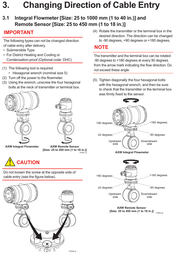
1. Adjustment of cable entry direction
Depending on the type of device, there may be differences in the adjustment method, and power off is required first. The core steps are as follows:
Equipment type, caliber range, tool requirements, adjustment angle range, key considerations
Integrated flow meter+small caliber remote sensor 25-450mm (1-18 inches) No. 5 hex wrench -90 °,+90 °,+180 ° (one step every 90 °). It is forbidden to loosen the screws on the opposite side of the cable inlet; Tighten 4 bolts diagonally after adjustment
Large caliber remote sensor (Style S1) 500-1800mm (20-72 inches) with 1.5 hex wrench and 46 hex wrench -140 ° to+180 °. First loosen the hex nut, then loosen the neck screw, adjust and tighten in sequence
Large caliber remote sensor (Style S2) 500-1800mm (20-72 inches) 5 # hex wrench -90 °,+90 °,+180 ° (one step every 90 °) integrated flowmeter, do not loosen the screws on the opposite side
Note: The cable entry direction cannot be adjusted for submersible and district heating/anti condensation types (optional code DHC).
2. Maintenance of transmitter
(1) Display unit adjustment (only supported by AXW4A, not supported by AXG1A)
Direction adjustment: After power off, use a No. 3 hex wrench to open the cover, loosen the 2 fixing screws of the display unit, rotate clockwise 90 ° (do not remove the connector), re tighten the screws, close the cover and lock it.
Display board replacement: After opening the cover, loosen the screws of the display board, unlock the connector according to the "UNLOCK" mark and pull it out. When installing the new board, align the interfaces to avoid cable entanglement, and torque the screws to 0.6 ± 0.05 N · m.
(2) Parameter backup and recovery
Backup location: Parameters can be backed up to the built-in memory of the display board, supporting "backup restore" (same device) and "copy" (same model/specification/software and hardware version device).
Matching requirements: When restoring/copying, it is necessary to ensure that the device model, communication code, motherboard/sensor board/display board software version, etc. are consistent (see Table 4.4 in the manual). For split type, sensor device information should be synchronized with transmitter parameters.
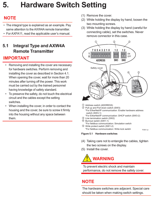
3. Hardware switch settings
According to the device type (integrated, AXW4A, AXG1A), the switch functions are different, and the core settings are as follows:
(1) Integrated and AXW4A remote transmitter
The switch is located below the display panel, including address switch, burn switch, write protection switch, etc. Key settings:
Key points for setting switch type functions
When the CPU of the burn switch (SW1-1) fails, the default current output direction is high output (>21.6mA); Option C1/C2 low output (<2.4mA)
Write protection switch (SW1-2) to prevent parameter overwrite ON: prohibit modification; OFF: Allow modification (effective in combination with software write protection)
Address switch (Address) device address (Modbus/PROFIBUS PA/EtherNet/IP) Modbus: 1-127 (0 automatically converted to 1); EtherNet/IP: Set IP segment 4 (1-244, all OFF/ON automatically converted to 210)
The line terminal switch (SW2) for Modbus bus terminal matching should be set to "Bus end" at both ends of the bus (SW2-1/2 both ON, 150 Ω resistor); Set the intermediate device to 'Not bus end'
(2) AXG1A remote transmitter
Only includes burn out switch (SW1-1) and write protect switch (SW1-2), with the same logic as AXW4A. It needs to be operated after opening the cover (using the corresponding tool) to avoid touching unrelated circuits.
Sensor inspection and health diagnosis
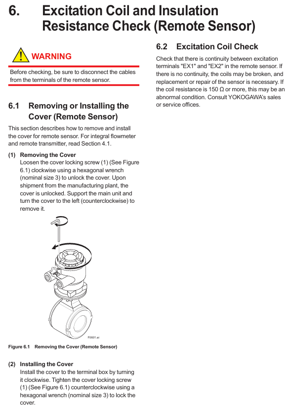
1. Excitation coil and insulation resistance inspection (only for remote sensors)
(1) Coil inspection
Step: After power off, disconnect the sensor terminal cable and use a multimeter to measure the continuity of the "EX1" and "EX2" terminals. If there is no continuity, the coil will be disconnected; Resistance ≥ 150 Ω is considered abnormal and requires contact with Yokogawa for maintenance.
(2) Insulation resistance inspection
The split coil circuit and signal circuit require a 500V DC insulation tester, with the following standards:
Precautions for Circuit Type Test Terminal Requirements
Coil circuit EX1 (excitation terminal) - C (common terminal) ≥ 1 M Ω. Fluid inside the pipeline can also be tested
Signal circuits C-A and C-B (signal terminals) ≥ 100 M Ω require emptying the pipeline and drying. Explosion proof type testing is prohibited
Note: The submersible and DHC types need to be measured at the cable terminal, not the sensor terminal.
2. Verification function (device health diagnosis)
(1) Functional positioning
Diagnosis of magnetic circuit, excitation circuit, calculation circuit, equipment status, and wiring connections can be done without dismantling the equipment, taking about 15 minutes to complete. It is recommended to perform it once every 1-2 years and operate it under full capacity (air traffic control may cause diagnostic abnormalities).
(2) Operation process
Parameter setting: Enter "Device setup ► Diag/Service ► Verification" through the display unit or communication tool, and set "Mode" (No flow/Flow) and "Execute" (execute/not execute).
Result judgment: After diagnosis, check the "Result", "Passed" is normal, and "Failed" needs to be checked according to the manual flowchart (if the magnetic circuit is abnormal, check the grounding, and if the wiring is abnormal, rewire); Cancelled "may be caused by alarms (such as air traffic control, signal overflow) or flow noise, and the alarm needs to be resolved first.
Troubleshooting
The manual provides troubleshooting flowcharts for three types of core faults, with the following key steps:
1. No display
First, confirm if there are any error prompts (through display or communication tools). If there are no errors, check if the sensor arrow is consistent with the flow direction (can be reinstalled or set with reverse flow parameters), if the sensor is full, and if the electrode adhesion detection function is enabled (wait for 4 minutes after enabling).
If the electrode resistance is greater than 4M Ω, the sensor needs to be removed to clean the electrode/grounding ring of foreign objects; If the verification function is still abnormal, the insulation resistance needs to be checked. If it is invalid, contact Yokogawa.
2. Zero point instability
Priority should be given to confirming that the pipeline is full, free of bubbles, and has no leaks; Check the grounding (the grounding ring is not corroded, the grounding wire is not broken), and perform the no current state verification function.
The conductivity of the fluid must meet the specifications (if unstable, control the temperature/flow rate); Equipment close to motors, transformers, etc. needs to be shielded or kept away from interference sources.
3. The displayed traffic does not match the actual amount
Check whether the parameters (instrument coefficient, caliber, etc.) are correct, whether the pipe is full, and whether the zero adjustment is performed in a no flow state; The signal cable needs to be insulated (to avoid contact between the shielding layer and the conductor).
The upstream straight pipe section must meet the installation requirements (refer to the installation manual); Insufficient conductivity or fluid fouling require cleaning of electrodes/liners. If ineffective, check insulation resistance or use a calibrator to determine transmitter/sensor failure.
- YOKOGAWA
- Reliance
- ADVANCED
- SEW
- ProSoft
- WATLOW
- Kongsberg
- FANUC
- VSD
- DCS
- PLC
- man-machine
- Covid-19
- Energy and Gender
- Energy Access
- Renewable Integration
- Energy Subsidies
- Energy and Water
- Net zero emission
- Energy Security
- Critical Minerals
- A-B
- petroleum
- Mine scale
- Sewage treatment
- cement
- architecture
- Industrial information
- New energy
- Automobile market
- electricity
- Construction site
- HIMA
- ABB
- Rockwell
- Schneider Modicon
- Siemens
- xYCOM
- Yaskawa
- Woodward
- BOSCH Rexroth
- MOOG
- General Electric
- American NI
- Rolls-Royce
- CTI
- Honeywell
- EMERSON
- MAN
- GE
- TRICONEX
- Control Wave
- ALSTOM
- AMAT
- STUDER
- KONGSBERG
- MOTOROLA
- DANAHER MOTION
- Bentley
- Galil
- EATON
- MOLEX
- Triconex
- DEIF
- B&W
- ZYGO
- Aerotech
- DANFOSS
- KOLLMORGEN
- Beijer
- Endress+Hauser
- schneider
- Foxboro
- KB
- REXROTH
- YAMAHA
- Johnson
- Westinghouse
- WAGO
- TOSHIBA
- TEKTRONIX
- BENDER
- BMCM
- SMC
- HITACHI
- HIRSCHMANN
- XP POWER
- Baldor
- Meggitt
- SHINKAWA
- Other Brands
- UniOP
- KUKA
- IBA
- Beckhoff
-
LTI SC52.0040.0012.0000.0 - Servo Drive
-
Lti SC52.0040.0012.0000.0 - Servo Drive
-
Milton Industries LTI Tool By Milton LT1240 - 1/2" Drive Lugnut Remover
-
LTi Drives SO84.200.P030.0000.0-W - Servo Spindle Drive
-
LTI DRIVES LSP08-035-320-30-B0R1PY170 - Servo Motor
-
LTI DRIVES SE84.200.SC00.0001.0-W - Servo Drive
-
Lust CDE34.005.W2.2 - Lti Drives Controller
-
LTi SO84.012.0030.0011.2 - ServoOne Servo Drive
-
LTi Drives SO CM-P.0010.11.00.0 - Servo Drive Controller
-
LTi CDE34.017.W3.0 - Servo Drive
-
LTI Drives CDB32.004, C2.0,SH - Positioning Controller
-
LUST CM-CAN1 - LTi DRIVES Communication Module
-
LTi SO84.012.1030.0000.2 - Servo Drive
-
LTI MOOG CDE54.044 - PITCHMASTER FREQUENCY CONVERTER 181-01019
-
MOOG LTI 181-01019 CDE54.044 - PITCHMASTER FREQUENCY CONVERTER
-
Lust LTi Drives CDE34.010,D2.0 - Servo Drive Controller
-
LTI SO84.032.0003.0101.2 - Servo Drive
-
Seagate 9CC132-302 Harris LTI-CS IRT-34-0021-01 - Hard Drive 160GB
-
LTI SO84.032.0003.0001.2 - Servo Drive
-
LTI SO24.007.0070.0000.1 - SERVO CONTROLLER
-
LTi drive CDA32.003.C3.0.H05-01.PC1 - Servo Drive
-
LTI SO84.016.0030.0000.2 - SERVO CONTROLLER
-
LUST LTI CD A34.008,W1.4, BR - SERVO DRIVE
-
MOOG LTI 181-01019 CDE54.044 - PITCHMASTER FREQUENCY CONVERTER
-
LTI MOOG 181-01019 - PITCH Master Servo Drive CDE54.044
-
LTI SERVO ONE SO84.045.0030.0001.2-W - Drive
-
LUST LTi SO84.032.0040.0000.2 - SERVO ONE DRIVE
-
LTi Drives LSH-074-2-30-3 20/T1,G6.1M - SERVO MOTOR
-
LTI SO84.016.0000.0101.2 - servo drive
-
LTI SA54.0550.0033.0000.0 - Servo Drive
-
LTI SA54.0550.0033.0000.0 - Servo Drive
-
LTI LT 4850 - 3/8" Drive 3-Pc Twist Socket Transmission Drain Plug Removal System
-
LTI Tools LT4400-30 Lock Technology - 3/4" Twist Socket 1/2" Drive Lugnut Remover
-
LTI Tools LT-1400C - 1/2 Drive Wheel Torque Extension Tool
-
LTI Tools LT1250 - 1/2" Drive Dual Sided Socket Lug Nut Remover Tool
-
LTI SO84.032.0003.0101.2 - Servo Drive
-
LTI MOOG 181-01019 - PITCH Master Servo Drive CDE54.044
-
MOOG LTI 181-01019 CDE54.044 - PITCHMASTER FREQUENCY CONVERTER
-
MOOG LTI 181-01019 CDE54.044 - PITCHMASTER FREQUENCY CONVERTER
-
MOOG LTI 181-01019 CDE54.044 - PITCHMASTER FREQUENCY CONVERTER
-
LTI SA54.0550.0033.0000.0 - Servo Drive
-
LTI Tools LT-4800 - 7 Piece Twist Socket 3/8" Drive Oil Drain Plug Removal Set
-
LTI SA54.0550.0033.0000.0 - Servo Drive
-
LTI Drive SO24.007.00300000.0 - Servo Drive
-
LTI TOOLS LTI 1400-I - Drive Wheel Torque Extension
-
LTI Tools LT4400-3 - 3/4" 19mm Twist Socket 1/2" Drive Lugnut
-
LTI TOOLS LTI 1400-BB - Drive Wheel Torque Extension
-
LTI SO84.032.0003.0101.2 - Servo Drive
-
LTI Tools LT-4512 - 3/8" Drive 12mm Twist Socket
-
LTI MOTION Luster SO84.032.0003.0001.2 - Servo Drive
-
LTI Tool By Milton LT1600P - 1" Drive Torx Stick
-
LTI Lust VF1424L,HF,OP2,S56 - Variable Frequency Drive
-
LUST CDA32.004,C1.4,H08,B0 - SERVO DFRIVE CM-CAN1 Module
-
LTI SO84.045.0002.0001.2-W - Drive
-
LTI Lust VF1404M,C9,PT1,BR1 - Inverter Type VF1404M
-
LTI SA54.0550.0033.0000.0 - Servo Drive
-
LTI Tools LT-1400C - 1/2" Drive Wheel Torque Extension
-
Lust LTI DRiVES CDA32.006, C3.0, H09 - Variateur De Fr茅quence Frequency Inverter
-
LTI MOOG CDE54.044 - PITCH master SERVO DRIVE
-
LTI MOOG CDE54.044 - PITCH master SERVO DRIVE
-
LTI SO84.143.0020.0101.2-W - servo drive
-
LTI MOTION SC34.0200.0011.0000.0 - Servo drives
-
LTI SO84.032.0003.0001.2 - Servo Drive
-
LTI DRIVES GmbH MS100 - Assembly Set Mounting Kit
-
LTI SO84.032.0003.0001.2 - Servo Drive
-
LTI SO84.032.0003.0001.2 - Servo Drive
-
LTI MOTION SO84.032.0003.0101.2 - servo drive
-
LTI SO84.032.0003.0101.2 - Servo Drive
-
LTI MOOG CDE54.044 - PITCH master SERVO DRIVE
-
LTI MOTION CDE32.004.C2.4 - Servo drives
-
LTI CDD34.032锛學x.x锛孊R锛孭C1 - Servo Drive
-
Lust LTI DRiVES CDA32.006, C3.0, H09 - Inversor De Frecuencia Frequency Inverter
-
Lust SO84.008.0030.1000.0 - Servo One LTi Drive
-
LTI MOTION SO84.032.0003.0101.2 - Servo drives
-
LUST LTi CDA32.004,C1.4 - SERVO DRIVE
-
LTI MOOG CDE54.044 - PITCH Master SERVO DRIVE
-
LTI KEBA CDB32.004 C2.7, SH - PN: 08673530 Frequency Inverter
-
LTI Tools LT-1400C - 1/2" Drive Wheel Torque Extension
-
LTI LT1400-E - 1/2" Drive Wheel Torque Extension
-
LTI MOOG 181-01019 - PITCH master SERVO DRIVE CDE54.044
-
LTI LSN-097-0510-30-560/T1 - Actuator Motor
-
LTI Tools LT 4800 - 7 Piece 3/8" Drive Twist Socket Oil Drain Plug Removal System
-
LTI DRIVES GmbH MS100 - MONTAGESET Assembly Set Mounting Kit
-
Lti SC52.0040.0012.0000.0 - Servo Drive
-
LTI DRIVES GmbH MS100 - Juego De Montaje Assembly Set Mounting Kit
-
LTi DSM4-14.2-21R83-200 - Drives servomoteur Servo Motor
-
MOOG CDE 54.044.GDA - Pitch Master Industrielle Turbine Lti Drive
-
LTI SO24.004.0030.1000.0 - Servo Drive Controller
-
Lti MOOG CDE54.044 - Pitch Master Servo Drive
-
Lust LTI DRiVES CDA32.006, C3.0, H09 - Inverter
-
LTI MOTION GMBH CDB34.006,W3.0,PC1,H39 - Frequency inverter
-
LTI SO84.032.0003.0001.2 - Servo Drive
-
MOOG CDE 54.044.D - Pitch Master Industrielle Turbine Lti Drive
-
LTI TOOLS LT-1460 - 1/2" DRIVE WHEEL TORQUE EXTENSION KIT 5 PIECE SET
-
Lust Cdb32.003, C2.4 - Lti Drives Servoregulador Frecuencia Servo Controller Inverter
-
Lust LTI DRIVES CDA32.006, C3.0, H09 - Frequency Inverter
-
Lust Lti SO82.004.0030.0000.2 - Servo Drive
-
LTI MOTION SC34.0200.0011.0000.0-SL - Servo drives
-
LTI MOTION SA54.0075.0033.0000.0 - Servo drives
-
LTI MOTION SC32.0075.1011.0000.0 - Servo drives
-
LTI Servo-One Junior SO22.006.0080.1000.0 - Servo Controller Servoregler
-
LUST CDA32.004, C1.4, H08, B0 - Servo Drive & LTI CM-CAN1 Module
-
LTI DRIVES LSP08-035-320-30-B0R1PY170 - Servo Motor
-
LUST LTI CDA32.004,C1.4.H08.B0 - SERVO CONTROLLER DRIVES
-
LUST LTi DRiVES CDS44.072LC1.2 - Servo Drive
-
Lti Servo-One Junior SO22.006.0082.1000.0 - Servo Controller Servoregler
-
LUST CDA32.008,C2.0,HF - Lti DRIVES Spindle Drive Inverter
-
LTI SO22.003.0082.0000.0 - Servo Drives One junior Servo Controller Servoregler
-
Lust Lti Drives CM-CAN1 - Communication Module
-
LUST Lti Drives Vf1202s, G8, I6 - Frequency Inverter Drive
-
LTI DRIVES BR-090.03.540.UR.H38 - Bremswiderstand Brake Resistor
-
LTi DRIVES PM-E40.2DRA054P - Wind Turbine Pitch Control Inverter
-
LTi Drives GmbH br-110.01.540-UR - Brake Resistor
-
LTI Drives LSN-097-0960-30-0560/T1,S4,B - Servo Motor
-
LUST CDA34.006.C2.0 - LTI Drives Servoregler
-
LUST LTI DRIVES SERVO ONE JUNIOR SO24.002.0020.0000.1 - Servo Drive Controller
-
LTI MOTION SO84.032.0003.0001.2 - Servo drives
-
LTI DDTD750V2-120 - IBOP ACTUATOR CYLINDER FOR TOP DRIVE
-
LTI CDE32.004, C2.4 - SERVO DRIVE
-
LUST LTI DRIVES CDD34.017 W3.4PC1 - Servo Drive Controller
-
LTI CDA3208,C3,0,HF - AC SERVO DRIVE
-
LUST LTI DRIVES LSH-074-3-30-560/T1,G6.1S - SERVO MOTOR
-
LUST Lti CDB32.004.C2.4.SH - AC Servo Drive
-
LTi CDA32.006, C3.0, H09 - Servo Drive
-
LTI SO22.003.0010.0000.0 - Servo Drive Servo one junior Servoregler Controller
-
LTi Drives DSM4-14.2-21R83-200 - Servo Motor
-
LUST Lti Drives Lsh-097-1-30-560/T1, 1R - Servomotor
-
LTI 1237 - 7 Piece 1/2" Drive Flip Socket Set

K-JIANG

Add: Jimei North Road, Jimei District, Xiamen, Fujian, China
Tell:+86-15305925923