
K-WANG


YOKOGAWA DO30G Dissolved Oxygen Sensor
YOKOGAWA DO30G Dissolved Oxygen Sensor
Equipment Overview and Adaptation System
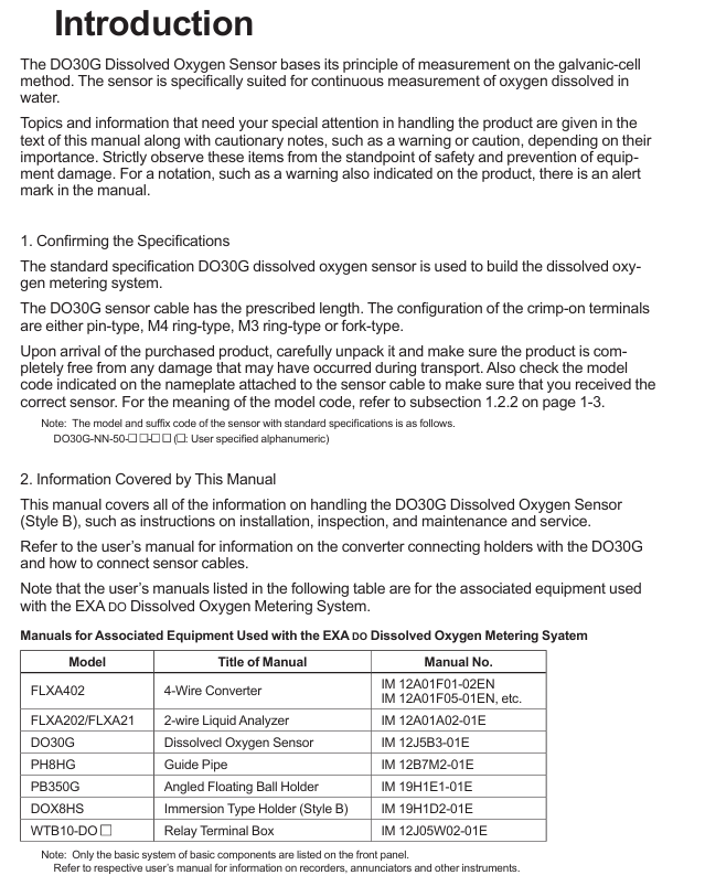
The core positioning of DO30G dissolved oxygen sensor is based on the principle of primary battery method, used for continuous measurement of dissolved oxygen concentration in water, suitable for environmental protection, water treatment and other scenarios. It needs to be combined with a supporting analyzer/converter to form a complete system and cannot be used alone.
Model coding rules
Standard model format: DO30G-NN-50-XX-YY, the meanings of each part are as follows:
-NN: Fixed suffix, no special meaning
-50: Permeable membrane thickness, fixed at 50 μ m
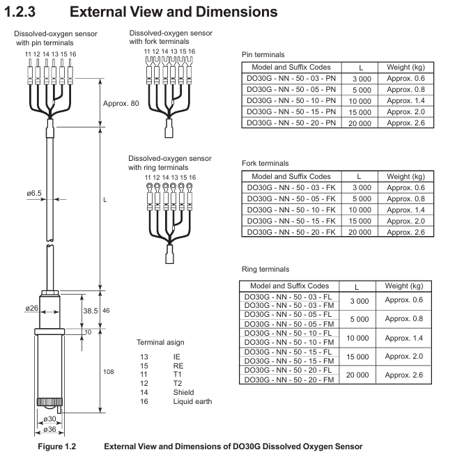
-XX: Cable length, optional -03 (3m), -05 (5m), -10 (10m), -15 (15m), -20 (20m)
-YY: Cable terminal types, - PN (pin type), - FK (fork type), - FL (M4 ring type), - FM (M3 ring type)
Key technical specifications
Specification category specific parameter remarks
Measurement parameter measurement range: 0-20 ppm, 0-20 mg/L, 0-100% (saturation). Specific ranges need to be set in the converter
Repeatability: 0.1 mg/L or 3% FS (whichever is greater) with sensor error included
Temperature compensation error: ± 3% FS (± 5 ℃ variation within 0-40 ℃) including sensor error
Response time: ≤ 2 minutes (90% response) including sensor error
Environmental requirements for measuring solution temperature: 0-40 ℃ (maximum value) Exceeding the range affects accuracy
Measure solution pressure: conventional 0-30 kPa, maximum 100 kPa, depth not exceeding 3m
Measure solution flow rate: ≥ 20 cm/s to prevent errors caused by bubble retention
Structural Material Sensor Unit: Hard PVC, Stainless Steel Resistant to Conventional Corrosion
Permeable membrane: Fluororesin (FEP) with a thickness of 50 μ m, requiring regular inspection
O-ring: Nitrile rubber sealing function, it needs to be replaced synchronously when replacing the membrane
Cable: heat-resistant flexible PVC, shielding design length 3-20m, terminal type selected according to requirements
Temperature compensation built-in RTD: PT1000 has a resistance of approximately 1097 Ω at 25 ℃, used to correct the effect of temperature on dissolved oxygen
The basic weight is 0.3 kg+0.12 × N kg (N is the length of the cable), and the total weight of a 5m cable is approximately 0.9 kg
Installation process and precautions
Pre-installation preparation
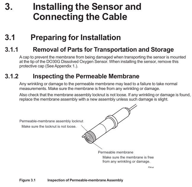
Remove protective cap: There is a black rubber protective cap on the tip of the sensor. It is forbidden to forcefully pull or twist it to remove it (which may cause the film to stretch/break). The correct way is to insert a 0.1-0.2mm thin rod and leave an air gap before pulling it out, or slowly rotate it clockwise to remove it (see Appendix 1 for details).
Check the permeable membrane: visually confirm that the membrane is not wrinkled or damaged, and that the membrane component lock nut is not loose (looseness can cause electrolyte leakage and affect measurement).
Principles for selecting measurement points
Uniform solution composition: avoid areas with frequent bubbles and stagnant water (to prevent fluctuations in measurement values).
Stay away from high velocity sand containing solutions: prevent sand particles from wearing down the permeable membrane.
Depth ≤ 3m: meets the pressure tolerance range (maximum 100 kPa).
Bracket selection and installation | Bracket type | Material/structure | Applicable scenarios | Installation points |
| Sensor tilted installation (anti bubble attachment), cleaning tube connected to water/air source for automatic cleaning|
cable connection
Match the converter according to the terminal number, taking FLXA402 as an example:
Temperature sensor (Pt1000): Connect terminal 11 (T1) and terminal 12 (T2) of the cable to the corresponding temperature terminals of the converter.
Electrode signal: Connect the 13 terminal (IE, anode) and 15 terminal (RE, cathode) of the cable to the corresponding electrode terminals of the converter.
Shielded wire: Connect to the shielded terminal of the converter to reduce interference.
Attention: Cable terminals must not be contaminated with water, and protection should be taken when not connected temporarily.
Maintenance and troubleshooting
Daily maintenance (regular inspection)
Permeation membrane cleaning: During each calibration, rinse the membrane surface with clean water, and wipe stubborn dirt with neutral detergent (do not scrape with hard objects to avoid membrane damage).
Membrane module lock nut inspection: Each calibration confirms that the lock nut is not loose, and if it is loose, it needs to be tightened; If there is still an abnormal display after tightening (such as extremely low measurement values), the electrolyte needs to be replaced.
Fault handling process
Troubleshooting steps and solutions
Abnormal measurement values (low/fluctuating) 1. Check if the membrane is damaged/wrinkled; 2. Check if the lock nut is loose; 3. Check if the electrolyte has deteriorated. 1. Replace the membrane module and electrolyte; 2. Tighten the nut lock; 3. Replace the electrolyte
If the temperature compensation fails and the resistance between terminals 11-12 of the measurement cable (standard value of 1097 Ω at 25 ℃) is abnormal, replace the sensor
Unable to zero/span 1. Replace membrane module+electrolyte and retry; 2. If the corrosion of the lead electrode is still ineffective, replace the sensor (lead electrode has a lifespan of 3-4 years)
Steps for replacing electrolyte and membrane components
Safety reminder: The electrolyte is KOH alkaline solution. If it comes into contact with the skin/eyes, rinse immediately with water and do not leave any residue in the syringe.
Steps:
Remove the sensor and clean the wet area;
Release the lock nut and remove the membrane component and old O-ring;
Empty the old electrolyte (tilt sensor, use a syringe to blow air from the injection port to assist in emptying);
Polishing silver electrode: Dip a damp gauze into aluminum oxide powder and gently wipe it (to avoid excessive polishing and prevent damage to the epoxy material), then clean the remaining powder;
Install a new O-ring, inject 8ml of new electrolyte (Yokogawa specific, model K9171DN), and reserve 1ml of air;
Install a new membrane component: Drop 1 drop of electrolyte on the surface of the silver electrode to prevent bubbles, lightly press the membrane component and tighten the locking nut (do not rotate the membrane component);
Rest: After replacement, it is necessary to rest for more than half a day before adjusting the zero/span (negative values may be displayed in the initial 10 minutes, which is a normal phenomenon).
Core spare parts list
DOX8A Maintenance Kit (Style B): Designed specifically for DO30G, it includes the following items:
Item Name Specification/Quantity Usage
Replace 50mL of electrolyte (model K9171DN) with 8ml each time
Replace damaged/contaminated membranes with 3 sets of membrane components and O-rings (model K9171HM)
500g of zero calibration reagent (sodium sulfite) (model L9920BR) is used to prepare a zero calibration solution (50g is required for 1L)
Inject 5ml (with needle, model L9827NH/L9827NG) of electrolyte into the syringe
200mL beaker (model L9825AF) for draining electrolyte/calibration purposes
30g of silver electrode polishing powder (model K9088PE) is used to polish silver electrodes, with approximately 0.5g used each time
Spare parts: membrane module lock nut (model K9171CH), spare sensor (to avoid measurement interruption caused by sudden failure).
Key issue
Question 1: How long does it take to replace the permeation membrane and electrolyte of DO30G sensor? What safety and operational details should be paid attention to when replacing?
answer:
Replacement cycle: It is recommended to replace the electrolyte every 6-8 months or immediately when the sensor cannot be adjusted for span; The permeable membrane and electrolyte should be replaced synchronously. If the membrane is damaged, wrinkled, or severely contaminated, it needs to be replaced in advance.
Safety details: The electrolyte is KOH alkaline solution. If it comes into contact with the skin, rinse immediately with clean water. If it enters the eyes, rinse and seek medical attention. Do not leave any residue in the syringe;
Operation details: When injecting electrolyte, add 8ml (Yokogawa specific model K9171DN) and reserve 1ml of air to prevent abnormal pressure; Before installing the membrane module, one drop of electrolyte should be dropped on the surface of the silver electrode to avoid the formation of bubbles between the membrane and the electrode; Do not rotate the membrane component when tightening the nut to prevent membrane wrinkling.
Question 2: There are three commonly used mounting brackets for DO30G sensors (PH8HG, PB350G, DOX8HS). How to choose according to the actual scenario? What are the core advantages and installation requirements of each bracket?
answer:
Selection of bracket type scene based on core advantages and installation requirements
PH8HG catheter measurement solution has no bubbles or pollutants (such as clear water tank), PVC material is corrosion-resistant, simple structure, low cost, and needs to be fixed on a pipeline with an outer diameter of 60.5mm. The sensor is suspended in a 2m long catheter
The PB350G floating ball bracket measures the solution level with large fluctuations and a small amount of flocculent substances (such as sedimentation tanks). The floating ball changes with the liquid level, and the sensor is always immersed in the solution; The wet part is smooth and not easy to hang flocs. The bracket is fixed on the 50A pipeline (outer diameter 60.5mm) or horizontal plane, and the float does not deviate from the measurement point
The DOX8HS immersion bracket measurement solution is prone to contamination (such as industrial wastewater) and needs to be regularly cleaned and installed at a 45 ° angle to prevent bubble adhesion; Support automatic cleaning with water/air spray to reduce the need for manual maintenance by connecting to a clean water/air source. The sensor is tilted and fixed to ensure that the cleaning spray port is aligned with the membrane surface
Question 3: When the DO30G sensor displays abnormal measurement values (such as continuous low or large fluctuations), how to gradually investigate the cause of the fault and solve it?
Answer: Troubleshooting should be carried out according to the following steps, with priority given to handling simple faults:
Check the condition of the permeable membrane: visually inspect the membrane for any damage, wrinkles, or severe contamination (such as oil stains or sediment). If there is, replace the membrane module (model K9171HM)+electrolyte; If the pollution is minor, clean with clean water and neutral detergent and try again;
Check the locking nut of the membrane module: confirm whether the locking nut is loose (looseness can cause electrolyte leakage, and the measured value is low). If it is loose, tighten it. If it is still abnormal after tightening, replace the electrolyte;
Check the status of the electrolyte: observe whether the electrolyte is turbid or discolored (normally clear), and replace it if it deteriorates;
Check temperature compensation: Use a multimeter to measure the resistance between terminals 11-12 of the cable (standard value of 1097 Ω at 25 ℃). If the resistance is abnormal, the sensor RTD is faulty and needs to be replaced;
Check the lead electrode: If the above steps are ineffective, it may be due to long-term corrosion failure of the lead electrode (with a lifespan of 3-4 years), and the sensor needs to be replaced as a whole.

- YOKOGAWA
- Reliance
- ADVANCED
- SEW
- ProSoft
- WATLOW
- Kongsberg
- FANUC
- VSD
- DCS
- PLC
- man-machine
- Covid-19
- Energy and Gender
- Energy Access
- Renewable Integration
- Energy Subsidies
- Energy and Water
- Net zero emission
- Energy Security
- Critical Minerals
- A-B
- petroleum
- Mine scale
- Sewage treatment
- cement
- architecture
- Industrial information
- New energy
- Automobile market
- electricity
- Construction site
- HIMA
- ABB
- Rockwell
- Schneider Modicon
- Siemens
- xYCOM
- Yaskawa
- Woodward
- BOSCH Rexroth
- MOOG
- General Electric
- American NI
- Rolls-Royce
- CTI
- Honeywell
- EMERSON
- MAN
- GE
- TRICONEX
- Control Wave
- ALSTOM
- AMAT
- STUDER
- KONGSBERG
- MOTOROLA
- DANAHER MOTION
- Bentley
- Galil
- EATON
- MOLEX
- Triconex
- DEIF
- B&W
- ZYGO
- Aerotech
- DANFOSS
- KOLLMORGEN
- Beijer
- Endress+Hauser
- schneider
- Foxboro
- KB
- REXROTH
- YAMAHA
- Johnson
- Westinghouse
- WAGO
- TOSHIBA
- TEKTRONIX
- BENDER
- BMCM
- SMC
- HITACHI
- HIRSCHMANN
- XP POWER
- Baldor
- Meggitt
- SHINKAWA
- Other Brands
- UniOP
- KUKA
- IBA
- Beckhoff
-
LTI SC52.0040.0012.0000.0 - Servo Drive
-
Lti SC52.0040.0012.0000.0 - Servo Drive
-
Milton Industries LTI Tool By Milton LT1240 - 1/2" Drive Lugnut Remover
-
LTi Drives SO84.200.P030.0000.0-W - Servo Spindle Drive
-
LTI DRIVES LSP08-035-320-30-B0R1PY170 - Servo Motor
-
LTI DRIVES SE84.200.SC00.0001.0-W - Servo Drive
-
Lust CDE34.005.W2.2 - Lti Drives Controller
-
LTi SO84.012.0030.0011.2 - ServoOne Servo Drive
-
LTi Drives SO CM-P.0010.11.00.0 - Servo Drive Controller
-
LTi CDE34.017.W3.0 - Servo Drive
-
LTI Drives CDB32.004, C2.0,SH - Positioning Controller
-
LUST CM-CAN1 - LTi DRIVES Communication Module
-
LTi SO84.012.1030.0000.2 - Servo Drive
-
LTI MOOG CDE54.044 - PITCHMASTER FREQUENCY CONVERTER 181-01019
-
MOOG LTI 181-01019 CDE54.044 - PITCHMASTER FREQUENCY CONVERTER
-
Lust LTi Drives CDE34.010,D2.0 - Servo Drive Controller
-
LTI SO84.032.0003.0101.2 - Servo Drive
-
Seagate 9CC132-302 Harris LTI-CS IRT-34-0021-01 - Hard Drive 160GB
-
LTI SO84.032.0003.0001.2 - Servo Drive
-
LTI SO24.007.0070.0000.1 - SERVO CONTROLLER
-
LTi drive CDA32.003.C3.0.H05-01.PC1 - Servo Drive
-
LTI SO84.016.0030.0000.2 - SERVO CONTROLLER
-
LUST LTI CD A34.008,W1.4, BR - SERVO DRIVE
-
MOOG LTI 181-01019 CDE54.044 - PITCHMASTER FREQUENCY CONVERTER
-
LTI MOOG 181-01019 - PITCH Master Servo Drive CDE54.044
-
LTI SERVO ONE SO84.045.0030.0001.2-W - Drive
-
LUST LTi SO84.032.0040.0000.2 - SERVO ONE DRIVE
-
LTi Drives LSH-074-2-30-3 20/T1,G6.1M - SERVO MOTOR
-
LTI SO84.016.0000.0101.2 - servo drive
-
LTI SA54.0550.0033.0000.0 - Servo Drive
-
LTI SA54.0550.0033.0000.0 - Servo Drive
-
LTI LT 4850 - 3/8" Drive 3-Pc Twist Socket Transmission Drain Plug Removal System
-
LTI Tools LT4400-30 Lock Technology - 3/4" Twist Socket 1/2" Drive Lugnut Remover
-
LTI Tools LT-1400C - 1/2 Drive Wheel Torque Extension Tool
-
LTI Tools LT1250 - 1/2" Drive Dual Sided Socket Lug Nut Remover Tool
-
LTI SO84.032.0003.0101.2 - Servo Drive
-
LTI MOOG 181-01019 - PITCH Master Servo Drive CDE54.044
-
MOOG LTI 181-01019 CDE54.044 - PITCHMASTER FREQUENCY CONVERTER
-
MOOG LTI 181-01019 CDE54.044 - PITCHMASTER FREQUENCY CONVERTER
-
MOOG LTI 181-01019 CDE54.044 - PITCHMASTER FREQUENCY CONVERTER
-
LTI SA54.0550.0033.0000.0 - Servo Drive
-
LTI Tools LT-4800 - 7 Piece Twist Socket 3/8" Drive Oil Drain Plug Removal Set
-
LTI SA54.0550.0033.0000.0 - Servo Drive
-
LTI Drive SO24.007.00300000.0 - Servo Drive
-
LTI TOOLS LTI 1400-I - Drive Wheel Torque Extension
-
LTI Tools LT4400-3 - 3/4" 19mm Twist Socket 1/2" Drive Lugnut
-
LTI TOOLS LTI 1400-BB - Drive Wheel Torque Extension
-
LTI SO84.032.0003.0101.2 - Servo Drive
-
LTI Tools LT-4512 - 3/8" Drive 12mm Twist Socket
-
LTI MOTION Luster SO84.032.0003.0001.2 - Servo Drive
-
LTI Tool By Milton LT1600P - 1" Drive Torx Stick
-
LTI Lust VF1424L,HF,OP2,S56 - Variable Frequency Drive
-
LUST CDA32.004,C1.4,H08,B0 - SERVO DFRIVE CM-CAN1 Module
-
LTI SO84.045.0002.0001.2-W - Drive
-
LTI Lust VF1404M,C9,PT1,BR1 - Inverter Type VF1404M
-
LTI SA54.0550.0033.0000.0 - Servo Drive
-
LTI Tools LT-1400C - 1/2" Drive Wheel Torque Extension
-
Lust LTI DRiVES CDA32.006, C3.0, H09 - Variateur De Fr茅quence Frequency Inverter
-
LTI MOOG CDE54.044 - PITCH master SERVO DRIVE
-
LTI MOOG CDE54.044 - PITCH master SERVO DRIVE
-
LTI SO84.143.0020.0101.2-W - servo drive
-
LTI MOTION SC34.0200.0011.0000.0 - Servo drives
-
LTI SO84.032.0003.0001.2 - Servo Drive
-
LTI DRIVES GmbH MS100 - Assembly Set Mounting Kit
-
LTI SO84.032.0003.0001.2 - Servo Drive
-
LTI SO84.032.0003.0001.2 - Servo Drive
-
LTI MOTION SO84.032.0003.0101.2 - servo drive
-
LTI SO84.032.0003.0101.2 - Servo Drive
-
LTI MOOG CDE54.044 - PITCH master SERVO DRIVE
-
LTI MOTION CDE32.004.C2.4 - Servo drives
-
LTI CDD34.032锛學x.x锛孊R锛孭C1 - Servo Drive
-
Lust LTI DRiVES CDA32.006, C3.0, H09 - Inversor De Frecuencia Frequency Inverter
-
Lust SO84.008.0030.1000.0 - Servo One LTi Drive
-
LTI MOTION SO84.032.0003.0101.2 - Servo drives
-
LUST LTi CDA32.004,C1.4 - SERVO DRIVE
-
LTI MOOG CDE54.044 - PITCH Master SERVO DRIVE
-
LTI KEBA CDB32.004 C2.7, SH - PN: 08673530 Frequency Inverter
-
LTI Tools LT-1400C - 1/2" Drive Wheel Torque Extension
-
LTI LT1400-E - 1/2" Drive Wheel Torque Extension
-
LTI MOOG 181-01019 - PITCH master SERVO DRIVE CDE54.044
-
LTI LSN-097-0510-30-560/T1 - Actuator Motor
-
LTI Tools LT 4800 - 7 Piece 3/8" Drive Twist Socket Oil Drain Plug Removal System
-
LTI DRIVES GmbH MS100 - MONTAGESET Assembly Set Mounting Kit
-
Lti SC52.0040.0012.0000.0 - Servo Drive
-
LTI DRIVES GmbH MS100 - Juego De Montaje Assembly Set Mounting Kit
-
LTi DSM4-14.2-21R83-200 - Drives servomoteur Servo Motor
-
MOOG CDE 54.044.GDA - Pitch Master Industrielle Turbine Lti Drive
-
LTI SO24.004.0030.1000.0 - Servo Drive Controller
-
Lti MOOG CDE54.044 - Pitch Master Servo Drive
-
Lust LTI DRiVES CDA32.006, C3.0, H09 - Inverter
-
LTI MOTION GMBH CDB34.006,W3.0,PC1,H39 - Frequency inverter
-
LTI SO84.032.0003.0001.2 - Servo Drive
-
MOOG CDE 54.044.D - Pitch Master Industrielle Turbine Lti Drive
-
LTI TOOLS LT-1460 - 1/2" DRIVE WHEEL TORQUE EXTENSION KIT 5 PIECE SET
-
Lust Cdb32.003, C2.4 - Lti Drives Servoregulador Frecuencia Servo Controller Inverter
-
Lust LTI DRIVES CDA32.006, C3.0, H09 - Frequency Inverter
-
Lust Lti SO82.004.0030.0000.2 - Servo Drive
-
LTI MOTION SC34.0200.0011.0000.0-SL - Servo drives
-
LTI MOTION SA54.0075.0033.0000.0 - Servo drives
-
LTI MOTION SC32.0075.1011.0000.0 - Servo drives
-
LTI Servo-One Junior SO22.006.0080.1000.0 - Servo Controller Servoregler
-
LUST CDA32.004, C1.4, H08, B0 - Servo Drive & LTI CM-CAN1 Module
-
LTI DRIVES LSP08-035-320-30-B0R1PY170 - Servo Motor
-
LUST LTI CDA32.004,C1.4.H08.B0 - SERVO CONTROLLER DRIVES
-
LUST LTi DRiVES CDS44.072LC1.2 - Servo Drive
-
Lti Servo-One Junior SO22.006.0082.1000.0 - Servo Controller Servoregler
-
LUST CDA32.008,C2.0,HF - Lti DRIVES Spindle Drive Inverter
-
LTI SO22.003.0082.0000.0 - Servo Drives One junior Servo Controller Servoregler
-
Lust Lti Drives CM-CAN1 - Communication Module
-
LUST Lti Drives Vf1202s, G8, I6 - Frequency Inverter Drive
-
LTI DRIVES BR-090.03.540.UR.H38 - Bremswiderstand Brake Resistor
-
LTi DRIVES PM-E40.2DRA054P - Wind Turbine Pitch Control Inverter
-
LTi Drives GmbH br-110.01.540-UR - Brake Resistor
-
LTI Drives LSN-097-0960-30-0560/T1,S4,B - Servo Motor
-
LUST CDA34.006.C2.0 - LTI Drives Servoregler
-
LUST LTI DRIVES SERVO ONE JUNIOR SO24.002.0020.0000.1 - Servo Drive Controller
-
LTI MOTION SO84.032.0003.0001.2 - Servo drives
-
LTI DDTD750V2-120 - IBOP ACTUATOR CYLINDER FOR TOP DRIVE
-
LTI CDE32.004, C2.4 - SERVO DRIVE
-
LUST LTI DRIVES CDD34.017 W3.4PC1 - Servo Drive Controller
-
LTI CDA3208,C3,0,HF - AC SERVO DRIVE
-
LUST LTI DRIVES LSH-074-3-30-560/T1,G6.1S - SERVO MOTOR
-
LUST Lti CDB32.004.C2.4.SH - AC Servo Drive
-
LTi CDA32.006, C3.0, H09 - Servo Drive
-
LTI SO22.003.0010.0000.0 - Servo Drive Servo one junior Servoregler Controller
-
LTi Drives DSM4-14.2-21R83-200 - Servo Motor
-
LUST Lti Drives Lsh-097-1-30-560/T1, 1R - Servomotor
-
LTI 1237 - 7 Piece 1/2" Drive Flip Socket Set

K-JIANG

Add: Jimei North Road, Jimei District, Xiamen, Fujian, China
Tell:+86-15305925923