
K-WANG


Yokogawa AQ1000 OTDR Optical Time Domain Reflectometer
Yokogawa AQ1000 OTDR Optical Time Domain Reflectometer
Core functions of the device
As an OTDR device, AQ1000 is primarily used to detect fiber optic fault locations, monitor transmission losses, fusion losses, and other parameters. Its main functions are as follows:
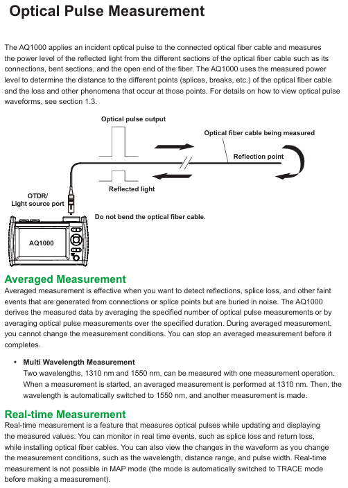
1. Optical pulse measurement function
Support two core measurement modes to meet different scenario requirements:
Average Measurement
TRACE mode: After multiple measurements, take the average of the data and display the results in waveform form to improve the signal-to-noise ratio. It can detect weak events that are masked by noise, such as fusion losses and reflections.
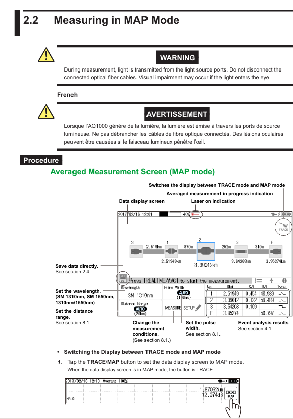
MAP mode: After completing the average measurement, the OTDR waveform is automatically analyzed, and various events (such as fusion points and bending points) are marked with icons. If the qualified/unqualified judgment conditions are preset, the judgment results will be displayed in the color of the icon.
Key feature: Supports one-time measurement of dual wavelengths of 1310nm and 1550nm (multi wavelength measurement). During measurement, the average measurement is completed at 1310nm first, and then automatically switches to 1550nm measurement.
Real time measurement
Only supports TRACE mode, with real-time waveform updates and displays during the measurement process. It can monitor events such as fusion loss and return loss in real time, as well as observe waveform changes when parameters such as wavelength, distance range, and pulse width change.
Limitation: Cannot be performed in MAP mode, it will automatically switch to TRACE mode after starting real-time measurement.
2. Data display and analysis function
The data shows
TRACE mode: The horizontal axis represents distance and the vertical axis represents loss level, displaying the waveform of optical pulse measurement. The waveform can be scaled and moved, and detected losses or reflections (referred to as "events") will be marked on the waveform.
MAP mode: Display all events from the measurement starting point to the fiber optic endpoint in order using icons, label the event type (such as fusion, bending, splitter) and distance from the starting point, and visually present the status of the fiber optic line.
data analysis
Waveform analysis: Measure the distance between two points, fusion loss, and return loss (inter marker return loss) through the cursor and markers.
Event analysis: Automatically detect events and display them on the screen (TRACE mode marked on the waveform, MAP mode displayed with icons), support event editing (insert/delete events, insert/delete distance reference point R), adjustable event detection conditions (such as fusion loss threshold, return loss threshold).
3. Pass/Fail Judgment
Judgment logic: Set a threshold for each measurement item. If the measurement value does not exceed the threshold, the event is judged as "Pass", and if it exceeds the threshold, it is judged as "Fail".
Judgment items: including connector loss, fusion loss, return loss, loss per kilometer between events (dB/km), and total loss.
The results show that in TRACE mode, qualified events have no special markings, while unqualified events are marked in red; In MAP mode, different colored icons are used to distinguish between them. The top progress bar is green when all events are qualified, and red when there are unqualified events.
4. Light source and power detection function
Stable Light Source
Transmit measurement light (continuous CW or modulated CHOP) from the OTDR port, with a wavelength consistent with the OTDR light pulse wavelength (1310nm/1550nm), for measuring optical loss or identifying optical fibers.
Visible light source (/VLS option)
Only supported by VLS option devices, emitting 650nm visible light (CW or 2Hz modulated CHOP) from the VLS port for visual inspection of fiber breakpoints and checking the core of multi-core fibers.
Power checker
Detect the presence of communication light (in use fiber) in the measured optical fiber through the OTDR port and check its power value. The supported wavelengths for measurement include 1310nm, 1490nm, 1550nm, 1625nm, and 1650nm.
5. Data storage and transmission function
File type and purpose
Characteristics of file format usage
. SOR stores the measurement results of optical pulses (including measurement/analysis conditions, waveform data, and event list data), which can display waveforms and event analysis results after loading. It only supports SOR files generated by AQ1000 devices
PDF stores the waveform data of the current screen or saved files in a report format. The report can be customized to include items such as job information, link summaries, and waveform diagrams
CFG storage system settings (devices, connections, etc.) can be used for unified configuration of multiple AQ1000 devices
. BMP/. JPG storage device screen images are only for viewing on a computer and cannot be loaded back into AQ1000
SOZ stores multiple waveforms measured simultaneously and only supports loading with AQ1000. When using AQ7933 OTDR simulation software for PC analysis, it needs to be split into SOR files
storage medium
Internal memory: Approximately 480MB, non removable, used for storing files and system files (such as the ACKUP and USERS-MANUAL folders).
USB storage medium: Supports USB 1.0/1.1/2.0 standard USB devices (Type A ports), which can store waveform data, measurement conditions, etc; The Type B Micro-B port can connect the device as a high-capacity storage device to a computer and operate internal files.
6. System auxiliary functions
Power saving mode: can set screen brightness (4 levels, including off), distinguish between battery powered and USB-AC adapter powered brightness; Support automatic sleep mode. After the device is turned on and there is no operation for the set time (1/5/10/30 minutes), it will automatically enter sleep mode. If there is no operation for 2 hours, it will automatically shut down.
Language and Display Settings: Supports multi language switching, and can set the initial screen (TRACE/MAP/Setup Info.) and screen color (Color 1/Color 2/Black and White) for startup.
Firmware update: Store the new firmware on a USB storage medium and connect it to the Type A port to update the device firmware.
Operation process (core scenario)
1. Average measurement (TRACE mode)
Mode switching: Click the TRACE/MAP button to ensure that the data is displayed in TRACE mode (the button displays as MAP).
Parameter settings: Click the Wavelength button to select the wavelength (1310nm/1550nm/1310nm+1550nm), set the distance range (automatic AUTO or manual, such as 200m-256km), and pulse width (automatic AUTO or manual, 3ns-20 μ s).
Start measurement: Press the AVG button, and the average measurement duration and laser on indicator will be displayed at the top of the screen. After the measurement is completed, it will automatically stop and perform event analysis, displaying waveforms and event results; Press the AVG button again to stop the measurement midway.
Data saving: Click on the floppy disk icon to save directly (in SOR/PDF/SOR+PDF format), or enable automatic saving in OTDR settings to automatically save data after measurement is completed.
2. Real time measurement (TRACE mode)
Parameter settings: Same as average measurement, select wavelength, distance range, pulse width (automatic or manual).
Start measurement: Press the REAL TIME button to activate the laser display and update the waveform in real-time; Press the REAL TIME button again to stop the measurement.
Data manipulation: During measurement, the cursor (displayed by clicking on the waveform position, dragging or clicking to move) and markers can be manipulated, and the current waveform data can also be saved (recording the waveform at the current time when saving).
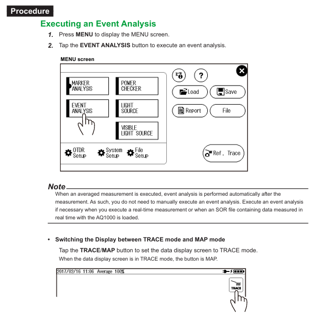
3. Event analysis (TRACE mode)
Perform analysis: Press the MENU button and click the EVENT Analysis button. The device will automatically analyze the waveform and display the event (after averaging the measurements, it will be automatically executed without manual operation; when performing real-time measurements or loading real-time measurement SOR files, manual execution is required).
Result view: Information such as event number, distance, fusion loss, return loss, and event type is displayed in three forms: List, Separate, and All. You can click on the corresponding label to switch.
Event editing: Click on the waveform display area, the cursor will appear and the event editing interface will pop up. You can insert events (move the cursor to the target position and click the insert button), delete events (move the cursor to the event ▲ mark and click the delete button), and insert/delete distance reference point R.
4. Setting of qualified/unqualified judgment
Enter Settings: Press the MENU button, click OTDR Setup, and in the Setup Info. menu, click on the EVENT ANALYSIS area to enter the EVENT ANALYSIS SETUP screen.
Enable Judgment: Click the Pass Fail Judgment button and set it to ON.
Threshold setting: Set the threshold for each judgment item (such as connector loss ≤ 1.00dB, fusion loss ≤ 0.10dB, return loss ≥ 70dB, etc.).
View result: After the average measurement is completed, the unqualified events in the event list are highlighted in red, and the progress bar at the top of the TRACE mode displays the overall judgment result (green/red).
Data management
1. USB storage media operation
Connection and detection: Supports hot swapping, connects USB storage media (Type A port) when the device is turned on, and the device automatically detects it; When connecting, it is necessary to directly plug into the port without using a USB hub, and avoid frequent plugging and unplugging in a short period of time (with an interval of ≥ 10 seconds).
Data reading and writing precautions: When the USB storage medium access indicator light flashes or data is read or written, the medium cannot be removed or turned off, otherwise it may damage the medium or data; Only supports FAT format USB devices, does not support encrypted or protected USB devices.
2. Data saving and loading
Data saving: Press the MENU button, click the Save button, select the storage medium (internal memory/USB), file format (SOR/SOZ/SOR+JPG), set the file name, and save; Support automatic saving, enable Auto Save in OTDR settings, select the save mode (by date/custom User Define) and storage path.
Data loading: Press the MENU button, click the Load button, select the storage medium and target file (SOR/CFG/SOZ/PDF), the corresponding data will be displayed after loading the SOR/SOZ/CFG file, and the content will be viewed through a PDF viewer after loading the PDF file.
3. Report generation
Single file report: Press the MENU button, click the Report button, select the SOR file that needs to generate the report, set the report content items (such as job information, link summary, waveform diagram), and generate a PDF format report.
Multi file report: Press the MENU button, click the File button, select multiple SOR files, click the export report icon, and batch generate PDF reports.
System settings (key items)
1. OTDR settings (measurement related)
Measurement settings: including wavelength, distance range, pulse width, average duration (automatic or manual, 5-30 minutes), automatic save (ON/OFF), in use fiber alarm (ON/OFF, detecting the presence of communication light in the fiber to avoid affecting communication), connection check (ON/OFF, prohibiting OTDR port from emitting light when the fiber is not properly connected).
Event Analysis Settings: Set event search criteria (fusion loss threshold 0.01-9.99dB, return loss threshold 20-70dB, fiber endpoint threshold 3-65dB, whether bending loss is detected), pass/fail judgment (ON/OFF and threshold for each judgment item), and transmit fiber settings (ON/OFF, set the length of the transmit fiber to eliminate the influence of near end blind spots).
Analysis settings: Set the refractive index (IOR, 130000-179999, default 1.46000), backscatter level (1 μ s pulse width: -10.00 to -64.99dB; 1ns pulse width: -40.00 to -94.99dB), and mark the approximate method (LSA least squares method/TPA two-point method).
2. File settings
File Name Setting: Select the file name components (wavelength, comments, company name, fiber ID, etc.), set the tape number type (OFF or a-b to a-h), delimiter (such as _,~), and ID number (0-9999).
Report settings: Check the contents included in the report (such as job information, link summary, MAP chart, TRACE waveform, event list, etc.).
Label setting: Fill in fiber related information (company name, fiber type, cable ID, starting/ending position, etc.), which will be saved with the SOR file for easy traceability.
3. System settings
Power management: Set the screen brightness (Bright/Normal/Power Save/OFF) and automatic sleep time when powered by the battery/USB-AC adapter.
Network settings (/WLN options): Supports access point mode (AP) and station mode (Station), sets SSID, encryption type (WPA2-PSK), password, IP address, subnet mask, etc., can remotely control devices or transmit data through wireless LAN.
Restore factory settings: Select "Setup" to reset settings only (without deleting internal memory files), or select "All" to reset settings and delete all files in the USER folder except for the user manual (the BACKUP folder will be rebuilt to its default state).
Wireless LAN usage (/WLN option)
1. Network configuration
General settings: Press the MENU key → System Setup → Network Setup → Common Setup, set the username (default anonymous) and password for wireless connection authentication.
Access Point Mode (AP): Set SSID (such as AQ1000_TEMP01), encryption type (WPA2PSK), password, broadcast channel (AUTO or 1-11ch), IP address (such as 192.168.0.2), subnet mask (255.255.255.0), DHCP allocation starting address (such as 192.168.0.100), with the device as the access point and wireless terminals directly connected.
Workstation mode: Select a fixed SSID (manually entered or selected from a list of detected access points), set a password, DHCP (automatically obtained or manually set IP), and connect the device as a workstation to the existing wireless LAN.
2. Data transmission and remote control
Data transmission: Press the MENU button → System Setup → WLAN application, click OTDR Data Transporter, the device enters standby mode, the wireless terminal (such as a mobile phone) connects to the corresponding SSID, starts the OTDR Data Transporter software (needs to be downloaded from Yokogawa official website), and the data in AQ1000 can be transmitted.
Remote control: Click on OTDR Remote Controller, the device enters standby mode, the wireless terminal (PC/phone) connects to SSID, and controls the device through Yokogawa OTDR Remote Controller software or browser (enter device IP address), supporting control mode (can operate device, download files) and view mode (only view screen, download files).
Maintenance and upkeep
1. Daily inspection and cleaning
Mechanical inspection: After power failure, check the appearance of the equipment for any damage or deformation, ensure that the switches, connectors, and screws are not loose, and that the switches and moving parts operate smoothly; After powering on, check that the startup screen is normal, the buttons can switch screens, and the touch screen operation is sensitive.
Cleaning:
External device: Power off and disconnect the USB-AC adapter, wipe with a wrung out damp cloth, and avoid chemicals such as diluents, benzene, and alcohol to prevent deformation and fading.
Optical adapter and fiber end face: After turning off the power, open the light source port cover, remove the optical adapter (unscrew the M2 screw), wipe the fiber end face with a lint free and residue free lens cleaner, clean and reinstall the adapter (tightening torque of about 0.12N-m).
2. Troubleshooting and Error Handling
Common troubleshooting:
Troubleshooting and Solutions for Malfunctions
Check the USB-AC adapter connection (plug, power cord, DC plug) for no display during startup; Charge the battery and confirm that the POWER LED is on; Press and hold the power button for 2 seconds to force startup; If the backup files are damaged due to abnormal shutdown, long press the MENU button and press the power button until the device starts up
Screen automatically turns off to check battery level (low battery automatically shuts down); View power-saving mode settings (automatic sleep mode after no operation for the set time)
Touch screen unresponsive. Remove gloves and operate with bare hands; If there is still no response, restart the device or restore the factory settings
Error code handling: When the device displays an error code, refer to section 10.2 of the manual. For example, code 510 (PLUG CHECK Error) requires checking or cleaning the connector, and code 902 (low battery level) requires charging or replacing the battery; Hardware faults such as code 505-508 and 939-948 require contacting a Yokogawa dealer for repair.
3. Storage and consumables replacement
Storage conditions: After cleaning the equipment, it should be stored in an environment with stable temperature/humidity, no direct sunlight, minimal dust, and no corrosive gases; When not in use for a long period of time (≥ 1 month), store the battery in an environment of 10-30 ℃ after charging to avoid overdischarging.
Consumables replacement cycle:
Suggested replacement cycle for component names
The actual lifespan of the battery after 500 charging cycles is affected by the usage environment and cannot be replaced by oneself. It is necessary to contact the dealer
Backup battery (lithium battery) needs to be replaced at Yokogawa factory for 5 years
The LCD screen needs to be replaced at the Yokogawa factory after approximately 30000 hours
Ferrule plugs need to be replaced at Yokogawa factory every year
Universal adapter needs to be repurchased after 1 year
USB port needs to be replaced at Yokogawa factory after 1500 insertions and removals
4. Calibration and scrapping
Calibration cycle: It is recommended to conduct regular calibration once a year to ensure stable equipment performance and detect faults early.
Equipment scrapping: The equipment contains lithium-ion batteries and cannot be disassembled by oneself. It is necessary to contact the Henghe distributor and dispose of it according to relevant regulations.
- YOKOGAWA
- Reliance
- ADVANCED
- SEW
- ProSoft
- WATLOW
- Kongsberg
- FANUC
- VSD
- DCS
- PLC
- man-machine
- Covid-19
- Energy and Gender
- Energy Access
- Renewable Integration
- Energy Subsidies
- Energy and Water
- Net zero emission
- Energy Security
- Critical Minerals
- A-B
- petroleum
- Mine scale
- Sewage treatment
- cement
- architecture
- Industrial information
- New energy
- Automobile market
- electricity
- Construction site
- HIMA
- ABB
- Rockwell
- Schneider Modicon
- Siemens
- xYCOM
- Yaskawa
- Woodward
- BOSCH Rexroth
- MOOG
- General Electric
- American NI
- Rolls-Royce
- CTI
- Honeywell
- EMERSON
- MAN
- GE
- TRICONEX
- Control Wave
- ALSTOM
- AMAT
- STUDER
- KONGSBERG
- MOTOROLA
- DANAHER MOTION
- Bentley
- Galil
- EATON
- MOLEX
- Triconex
- DEIF
- B&W
- ZYGO
- Aerotech
- DANFOSS
- KOLLMORGEN
- Beijer
- Endress+Hauser
- schneider
- Foxboro
- KB
- REXROTH
- YAMAHA
- Johnson
- Westinghouse
- WAGO
- TOSHIBA
- TEKTRONIX
- BENDER
- BMCM
- SMC
- HITACHI
- HIRSCHMANN
- XP POWER
- Baldor
- Meggitt
- SHINKAWA
- Other Brands
- UniOP
- KUKA
- IBA
- Beckhoff
-
LTI SC52.0040.0012.0000.0 - Servo Drive
-
Lti SC52.0040.0012.0000.0 - Servo Drive
-
Milton Industries LTI Tool By Milton LT1240 - 1/2" Drive Lugnut Remover
-
LTi Drives SO84.200.P030.0000.0-W - Servo Spindle Drive
-
LTI DRIVES LSP08-035-320-30-B0R1PY170 - Servo Motor
-
LTI DRIVES SE84.200.SC00.0001.0-W - Servo Drive
-
Lust CDE34.005.W2.2 - Lti Drives Controller
-
LTi SO84.012.0030.0011.2 - ServoOne Servo Drive
-
LTi Drives SO CM-P.0010.11.00.0 - Servo Drive Controller
-
LTi CDE34.017.W3.0 - Servo Drive
-
LTI Drives CDB32.004, C2.0,SH - Positioning Controller
-
LUST CM-CAN1 - LTi DRIVES Communication Module
-
LTi SO84.012.1030.0000.2 - Servo Drive
-
LTI MOOG CDE54.044 - PITCHMASTER FREQUENCY CONVERTER 181-01019
-
MOOG LTI 181-01019 CDE54.044 - PITCHMASTER FREQUENCY CONVERTER
-
Lust LTi Drives CDE34.010,D2.0 - Servo Drive Controller
-
LTI SO84.032.0003.0101.2 - Servo Drive
-
Seagate 9CC132-302 Harris LTI-CS IRT-34-0021-01 - Hard Drive 160GB
-
LTI SO84.032.0003.0001.2 - Servo Drive
-
LTI SO24.007.0070.0000.1 - SERVO CONTROLLER
-
LTi drive CDA32.003.C3.0.H05-01.PC1 - Servo Drive
-
LTI SO84.016.0030.0000.2 - SERVO CONTROLLER
-
LUST LTI CD A34.008,W1.4, BR - SERVO DRIVE
-
MOOG LTI 181-01019 CDE54.044 - PITCHMASTER FREQUENCY CONVERTER
-
LTI MOOG 181-01019 - PITCH Master Servo Drive CDE54.044
-
LTI SERVO ONE SO84.045.0030.0001.2-W - Drive
-
LUST LTi SO84.032.0040.0000.2 - SERVO ONE DRIVE
-
LTi Drives LSH-074-2-30-3 20/T1,G6.1M - SERVO MOTOR
-
LTI SO84.016.0000.0101.2 - servo drive
-
LTI SA54.0550.0033.0000.0 - Servo Drive
-
LTI SA54.0550.0033.0000.0 - Servo Drive
-
LTI LT 4850 - 3/8" Drive 3-Pc Twist Socket Transmission Drain Plug Removal System
-
LTI Tools LT4400-30 Lock Technology - 3/4" Twist Socket 1/2" Drive Lugnut Remover
-
LTI Tools LT-1400C - 1/2 Drive Wheel Torque Extension Tool
-
LTI Tools LT1250 - 1/2" Drive Dual Sided Socket Lug Nut Remover Tool
-
LTI SO84.032.0003.0101.2 - Servo Drive
-
LTI MOOG 181-01019 - PITCH Master Servo Drive CDE54.044
-
MOOG LTI 181-01019 CDE54.044 - PITCHMASTER FREQUENCY CONVERTER
-
MOOG LTI 181-01019 CDE54.044 - PITCHMASTER FREQUENCY CONVERTER
-
MOOG LTI 181-01019 CDE54.044 - PITCHMASTER FREQUENCY CONVERTER
-
LTI SA54.0550.0033.0000.0 - Servo Drive
-
LTI Tools LT-4800 - 7 Piece Twist Socket 3/8" Drive Oil Drain Plug Removal Set
-
LTI SA54.0550.0033.0000.0 - Servo Drive
-
LTI Drive SO24.007.00300000.0 - Servo Drive
-
LTI TOOLS LTI 1400-I - Drive Wheel Torque Extension
-
LTI Tools LT4400-3 - 3/4" 19mm Twist Socket 1/2" Drive Lugnut
-
LTI TOOLS LTI 1400-BB - Drive Wheel Torque Extension
-
LTI SO84.032.0003.0101.2 - Servo Drive
-
LTI Tools LT-4512 - 3/8" Drive 12mm Twist Socket
-
LTI MOTION Luster SO84.032.0003.0001.2 - Servo Drive
-
LTI Tool By Milton LT1600P - 1" Drive Torx Stick
-
LTI Lust VF1424L,HF,OP2,S56 - Variable Frequency Drive
-
LUST CDA32.004,C1.4,H08,B0 - SERVO DFRIVE CM-CAN1 Module
-
LTI SO84.045.0002.0001.2-W - Drive
-
LTI Lust VF1404M,C9,PT1,BR1 - Inverter Type VF1404M
-
LTI SA54.0550.0033.0000.0 - Servo Drive
-
LTI Tools LT-1400C - 1/2" Drive Wheel Torque Extension
-
Lust LTI DRiVES CDA32.006, C3.0, H09 - Variateur De Fr茅quence Frequency Inverter
-
LTI MOOG CDE54.044 - PITCH master SERVO DRIVE
-
LTI MOOG CDE54.044 - PITCH master SERVO DRIVE
-
LTI SO84.143.0020.0101.2-W - servo drive
-
LTI MOTION SC34.0200.0011.0000.0 - Servo drives
-
LTI SO84.032.0003.0001.2 - Servo Drive
-
LTI DRIVES GmbH MS100 - Assembly Set Mounting Kit
-
LTI SO84.032.0003.0001.2 - Servo Drive
-
LTI SO84.032.0003.0001.2 - Servo Drive
-
LTI MOTION SO84.032.0003.0101.2 - servo drive
-
LTI SO84.032.0003.0101.2 - Servo Drive
-
LTI MOOG CDE54.044 - PITCH master SERVO DRIVE
-
LTI MOTION CDE32.004.C2.4 - Servo drives
-
LTI CDD34.032锛學x.x锛孊R锛孭C1 - Servo Drive
-
Lust LTI DRiVES CDA32.006, C3.0, H09 - Inversor De Frecuencia Frequency Inverter
-
Lust SO84.008.0030.1000.0 - Servo One LTi Drive
-
LTI MOTION SO84.032.0003.0101.2 - Servo drives
-
LUST LTi CDA32.004,C1.4 - SERVO DRIVE
-
LTI MOOG CDE54.044 - PITCH Master SERVO DRIVE
-
LTI KEBA CDB32.004 C2.7, SH - PN: 08673530 Frequency Inverter
-
LTI Tools LT-1400C - 1/2" Drive Wheel Torque Extension
-
LTI LT1400-E - 1/2" Drive Wheel Torque Extension
-
LTI MOOG 181-01019 - PITCH master SERVO DRIVE CDE54.044
-
LTI LSN-097-0510-30-560/T1 - Actuator Motor
-
LTI Tools LT 4800 - 7 Piece 3/8" Drive Twist Socket Oil Drain Plug Removal System
-
LTI DRIVES GmbH MS100 - MONTAGESET Assembly Set Mounting Kit
-
Lti SC52.0040.0012.0000.0 - Servo Drive
-
LTI DRIVES GmbH MS100 - Juego De Montaje Assembly Set Mounting Kit
-
LTi DSM4-14.2-21R83-200 - Drives servomoteur Servo Motor
-
MOOG CDE 54.044.GDA - Pitch Master Industrielle Turbine Lti Drive
-
LTI SO24.004.0030.1000.0 - Servo Drive Controller
-
Lti MOOG CDE54.044 - Pitch Master Servo Drive
-
Lust LTI DRiVES CDA32.006, C3.0, H09 - Inverter
-
LTI MOTION GMBH CDB34.006,W3.0,PC1,H39 - Frequency inverter
-
LTI SO84.032.0003.0001.2 - Servo Drive
-
MOOG CDE 54.044.D - Pitch Master Industrielle Turbine Lti Drive
-
LTI TOOLS LT-1460 - 1/2" DRIVE WHEEL TORQUE EXTENSION KIT 5 PIECE SET
-
Lust Cdb32.003, C2.4 - Lti Drives Servoregulador Frecuencia Servo Controller Inverter
-
Lust LTI DRIVES CDA32.006, C3.0, H09 - Frequency Inverter
-
Lust Lti SO82.004.0030.0000.2 - Servo Drive
-
LTI MOTION SC34.0200.0011.0000.0-SL - Servo drives
-
LTI MOTION SA54.0075.0033.0000.0 - Servo drives
-
LTI MOTION SC32.0075.1011.0000.0 - Servo drives
-
LTI Servo-One Junior SO22.006.0080.1000.0 - Servo Controller Servoregler
-
LUST CDA32.004, C1.4, H08, B0 - Servo Drive & LTI CM-CAN1 Module
-
LTI DRIVES LSP08-035-320-30-B0R1PY170 - Servo Motor
-
LUST LTI CDA32.004,C1.4.H08.B0 - SERVO CONTROLLER DRIVES
-
LUST LTi DRiVES CDS44.072LC1.2 - Servo Drive
-
Lti Servo-One Junior SO22.006.0082.1000.0 - Servo Controller Servoregler
-
LUST CDA32.008,C2.0,HF - Lti DRIVES Spindle Drive Inverter
-
LTI SO22.003.0082.0000.0 - Servo Drives One junior Servo Controller Servoregler
-
Lust Lti Drives CM-CAN1 - Communication Module
-
LUST Lti Drives Vf1202s, G8, I6 - Frequency Inverter Drive
-
LTI DRIVES BR-090.03.540.UR.H38 - Bremswiderstand Brake Resistor
-
LTi DRIVES PM-E40.2DRA054P - Wind Turbine Pitch Control Inverter
-
LTi Drives GmbH br-110.01.540-UR - Brake Resistor
-
LTI Drives LSN-097-0960-30-0560/T1,S4,B - Servo Motor
-
LUST CDA34.006.C2.0 - LTI Drives Servoregler
-
LUST LTI DRIVES SERVO ONE JUNIOR SO24.002.0020.0000.1 - Servo Drive Controller
-
LTI MOTION SO84.032.0003.0001.2 - Servo drives
-
LTI DDTD750V2-120 - IBOP ACTUATOR CYLINDER FOR TOP DRIVE
-
LTI CDE32.004, C2.4 - SERVO DRIVE
-
LUST LTI DRIVES CDD34.017 W3.4PC1 - Servo Drive Controller
-
LTI CDA3208,C3,0,HF - AC SERVO DRIVE
-
LUST LTI DRIVES LSH-074-3-30-560/T1,G6.1S - SERVO MOTOR
-
LUST Lti CDB32.004.C2.4.SH - AC Servo Drive
-
LTi CDA32.006, C3.0, H09 - Servo Drive
-
LTI SO22.003.0010.0000.0 - Servo Drive Servo one junior Servoregler Controller
-
LTi Drives DSM4-14.2-21R83-200 - Servo Motor
-
LUST Lti Drives Lsh-097-1-30-560/T1, 1R - Servomotor
-
LTI 1237 - 7 Piece 1/2" Drive Flip Socket Set

K-JIANG

Add: Jimei North Road, Jimei District, Xiamen, Fujian, China
Tell:+86-15305925923