
K-WANG


YOKOGAWA WT1801R series precision power analyzer communication interface
YOKOGAWA WT1801R series precision power analyzer communication interface
Overview
The communication interface user guide for YOKOGAWA WT1801R, WT1802R, WT1803R, WT1804R, WT1805R, and WT1806R series precision power analyzers was first released in October 2024. The core of the document revolves around the three communication interfaces of the instrument (Ethernet, USB, GP-IB), providing detailed explanations of interface functions, configuration methods, programming instructions, and status reporting mechanisms. It also provides a document system, terminology conventions, and global contact information, aiming to help users achieve remote control and data exchange of the instrument through PC.
Core Communication Interface Functions and Configuration
1. Ethernet interface
(1) Core Features and Specifications
Compatibility: Compliant with IEEE 802.3 standard and supports TCP/IP (VXI-11) communication protocol.
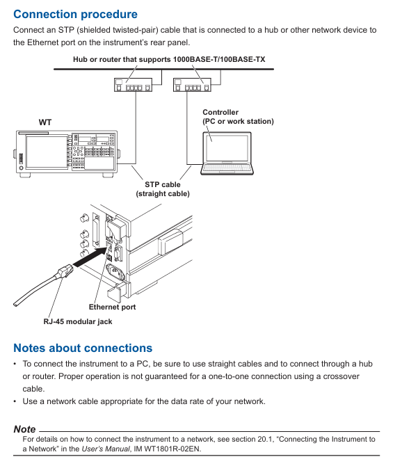
Connection capability: Supports connection with PC through hub/router, does not support cross line direct connection; The maximum number of simultaneous connections is limited by network devices.
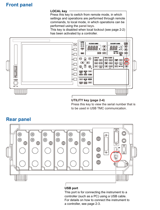
Remote control switch: Receive: Communicate: REMote ON/OFF command to switch between remote/local mode. In remote mode, only the LOCAL key is available (disabled when local is locked).
Timeout setting: The network connection timeout time can be set (1-3600 seconds or "infinite"), and the connection will be automatically disconnected after timeout. The default is "infinite".
(2) Configuration steps
Hardware connection: Use shielded twisted pair (STP) to connect the Ethernet port of the instrument Rear panel to the hub/router.
Enter the configuration menu: Press the UTIL key on the panel → click the Remote Control soft key → select the Network soft key to enter the network settings interface.
TCP/IP settings: IP address, subnet mask, and default gateway need to be configured (refer to section 20.2 of the IM WT1801R-02EN user manual for detailed steps).
Timeout setting: In the network settings interface, adjust the timeout time (Infinite or 1-3600s) through the cursor keys.
2. USB interface (USB-TMC)
(1) Core Features and Specifications
Compatibility: Compliant with USB 3.0 standard, supports USB-TMC (Test Measurement Class) protocol, requires installation of Yokogawa dedicated USB driver.
System requirements: Only supports Windows 10/11 system, PC needs to install communication library (TMCTL) and USB device driver (official website) https://tmi.yokogawa.com/ Downloadable).
Remote mode switching: Consistent with the Ethernet interface logic, it can be switched using the COMMunicate command or LOCAL key, and supports local locking.
Uniqueness: Only one USB device connection is supported at a time and cannot be used simultaneously with Ethernet or GP-IB interfaces.
(2) Configuration steps
Hardware connection: Connect the USB port of the instrument Rear panel to the PC using a USB Type B cable, and wait for 20-30 seconds after booting up before operating (to avoid damaging the device).
Driver installation: Download and install the Yokogawa USB TMC driver from the official website, and prohibit the use of third-party drivers.
View device serial number: Press the UTIL key → click on the Remote Control soft key → select the USB soft key to view the device serial number required for USB-TMC communication.
3. GP-IB interface (IEEE 488)
(1) Core Features and Specifications
Compatibility: Compliant with IEEE 488-1978 (Mechanical/Electrical) and IEEE 488.2-1992 (Protocol) standards, supports National Instruments GP-IB cards (such as PCIe GPIB, GPIB-UB-HS+).
Functional subset: Supports SH1 (source handshake), AH1 (receive handshake), T6 (basic talker), L4 (basic listener), SR1 (service request) and other functional subsets, without controller capability.
Address setting: The address range is 0-30, and each device on the bus needs to be assigned a unique address to avoid conflicts.
Connection restriction: The bus can connect up to 15 devices (including controllers), with a single cable length of ≤ 2 meters and a total length of ≤ 20 meters.
(2) Configuration steps
Hardware connection: In the shutdown state, use a 24 pin GP-IB cable to connect the GP-IB port of the instrument Rear panel to the GP-IB board of the PC, and tighten the connector screws.
Address configuration: Press the UTIL key → click the Remote Control soft key → select the GP-IB soft key, and set the address (0-30).
Interface response: Supports interface messages such as IFC (interface clearing), REN (remote enable), SDC (selected device clearing), etc. Please refer to section 3.5 of the document for specific response logic.
Fundamentals of Programming and Instruction System
1. Core programming concepts
Message types: divided into "program messages" (instructions sent by the PC to the instrument, such as configuration instructions and query instructions) and "response messages" (data returned by the instrument to the PC, such as measurement results and status information).
Instruction structure:
Common instruction: IEEE 488.2 standard instruction, starting with * (such as * CLS clearing status register, * IDN?)? Check the instrument model).
Composite instruction: Instrument specific hierarchical instruction, separated by: (e.g. DISPlay: MODE NUMeric to set display mode to numerical display).
Simple instruction: Non hierarchical independent instruction (such as HOLD to set data hold).
Data format: Supports decimal (NR1/NR2/NR3), physical quantities (with units, such as 100V), registers (binary/octal/hexadecimal), strings (user-defined, such as file names), and other formats.
2. Core instruction grouping and functions
Chapter 5 of the document provides a detailed list of 23 instruction groups, covering scenarios such as interface control, display settings, data storage, measurement and calculation. The key instruction groups are as follows:
Instruction group core instruction example function description
COMMunicate Group :COMMunicate:REMote ON
: Communicate: READer OFF controls remote/local mode, sets response with header information
DISPlay Group :DISPlay:MODE WAVE
DISPlay: WAVE: TDIV 5MS Set display mode (waveform/value/trend), adjust waveform timeline scale
FILE Group :FILE:SAVE:NUMeric "DATA1"
: FILE: LOAD: SETup "SET1" saves numerical data to a file, loads instrument settings file
MEASure Group :MEASure:AVERaging:STATE ON
MEASure: FUNCtion1: EXPResolution "URMS (E1)" Enable data averaging function and define user-defined measurement functions
NUMeric Group :NUMeric[:NORMal]:VALue?
NUMeric: FORM ASCII queries numerical measurement data, sets data output format (ASCII/FLOAT)
STORe Group :STORe:START
: STORe: FILE: CONVert: EXECUTE "STR1" Start storing data and convert stored data to CSV format
Common Command *IDN?
*OPC? Query instrument identification (model/serial number), query operation completion status
3. Synchronization and status reporting
Synchronization mechanism: through * WAI (waiting for operation completion),: Communicate: WAIT (waiting for specified event), * OPC? (Operation completion query) Avoid instruction execution conflicts and ensure data consistency.
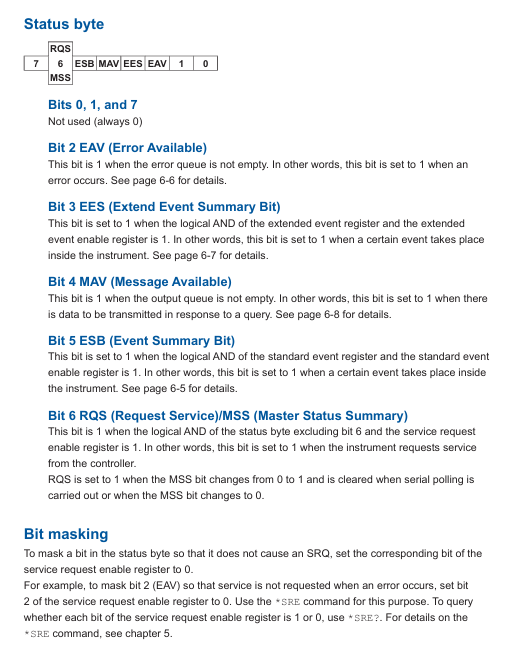
Status report: includes status bytes, standard event registers, extended event registers, and error queues, supported through: Status: ERRor? Query error codes and messages through * STB? Query status bytes to help locate communication or operational anomalies.
Modbus/TCP communication (extended functionality)
Function Overview: Supports Modbus/TCP protocol, can communicate with client devices (such as PLC, SCADA systems), and achieve register read/write and data interaction.
Register configuration: Chapter 7 of the document provides detailed definitions of register addresses and functions, covering measurement data, instrument status, configuration parameters, etc. It supports reading real-time data such as voltage, current, power, etc. through Modbus commands.
Communication process: The client needs to connect to the instrument's IP address and port (default 502) through TCP, and send Modbus function codes (such as 03H read hold registers) to achieve data exchange.
Precautions and Compatibility
Interface exclusivity: Ethernet, USB, and GP-IB interfaces cannot be used simultaneously and need to be manually switched or specified as a unique active interface through commands to avoid command conflicts.
Driver and library dependencies: USB and Ethernet interfaces require the installation of Yokogawa Communication Library (TMCTL) and drivers, and only support Windows systems, not compatible with third-party drivers.
Cable and Connection: GP-IB requires cables that comply with IEEE standards, Ethernet needs to be connected through a hub/router (cross wiring is not supported), and USB needs to be plugged in and unplugged after the instrument is turned on and stabilized.
Legacy compatibility: Chapter 8 of the document provides instructions for compatibility with WT1600, WT1800, and WT1800E series legacy instruments, facilitating smooth migration for existing users.
- YOKOGAWA
- Reliance
- ADVANCED
- SEW
- ProSoft
- WATLOW
- Kongsberg
- FANUC
- VSD
- DCS
- PLC
- man-machine
- Covid-19
- Energy and Gender
- Energy Access
- Renewable Integration
- Energy Subsidies
- Energy and Water
- Net zero emission
- Energy Security
- Critical Minerals
- A-B
- petroleum
- Mine scale
- Sewage treatment
- cement
- architecture
- Industrial information
- New energy
- Automobile market
- electricity
- Construction site
- HIMA
- ABB
- Rockwell
- Schneider Modicon
- Siemens
- xYCOM
- Yaskawa
- Woodward
- BOSCH Rexroth
- MOOG
- General Electric
- American NI
- Rolls-Royce
- CTI
- Honeywell
- EMERSON
- MAN
- GE
- TRICONEX
- Control Wave
- ALSTOM
- AMAT
- STUDER
- KONGSBERG
- MOTOROLA
- DANAHER MOTION
- Bentley
- Galil
- EATON
- MOLEX
- Triconex
- DEIF
- B&W
- ZYGO
- Aerotech
- DANFOSS
- KOLLMORGEN
- Beijer
- Endress+Hauser
- schneider
- Foxboro
- KB
- REXROTH
- YAMAHA
- Johnson
- Westinghouse
- WAGO
- TOSHIBA
- TEKTRONIX
- BENDER
- BMCM
- SMC
- HITACHI
- HIRSCHMANN
- XP POWER
- Baldor
- Meggitt
- SHINKAWA
- Other Brands
- UniOP
- KUKA
- IBA
- Beckhoff
-
LTI SC52.0040.0012.0000.0 - Servo Drive
-
Lti SC52.0040.0012.0000.0 - Servo Drive
-
Milton Industries LTI Tool By Milton LT1240 - 1/2" Drive Lugnut Remover
-
LTi Drives SO84.200.P030.0000.0-W - Servo Spindle Drive
-
LTI DRIVES LSP08-035-320-30-B0R1PY170 - Servo Motor
-
LTI DRIVES SE84.200.SC00.0001.0-W - Servo Drive
-
Lust CDE34.005.W2.2 - Lti Drives Controller
-
LTi SO84.012.0030.0011.2 - ServoOne Servo Drive
-
LTi Drives SO CM-P.0010.11.00.0 - Servo Drive Controller
-
LTi CDE34.017.W3.0 - Servo Drive
-
LTI Drives CDB32.004, C2.0,SH - Positioning Controller
-
LUST CM-CAN1 - LTi DRIVES Communication Module
-
LTi SO84.012.1030.0000.2 - Servo Drive
-
LTI MOOG CDE54.044 - PITCHMASTER FREQUENCY CONVERTER 181-01019
-
MOOG LTI 181-01019 CDE54.044 - PITCHMASTER FREQUENCY CONVERTER
-
Lust LTi Drives CDE34.010,D2.0 - Servo Drive Controller
-
LTI SO84.032.0003.0101.2 - Servo Drive
-
Seagate 9CC132-302 Harris LTI-CS IRT-34-0021-01 - Hard Drive 160GB
-
LTI SO84.032.0003.0001.2 - Servo Drive
-
LTI SO24.007.0070.0000.1 - SERVO CONTROLLER
-
LTi drive CDA32.003.C3.0.H05-01.PC1 - Servo Drive
-
LTI SO84.016.0030.0000.2 - SERVO CONTROLLER
-
LUST LTI CD A34.008,W1.4, BR - SERVO DRIVE
-
MOOG LTI 181-01019 CDE54.044 - PITCHMASTER FREQUENCY CONVERTER
-
LTI MOOG 181-01019 - PITCH Master Servo Drive CDE54.044
-
LTI SERVO ONE SO84.045.0030.0001.2-W - Drive
-
LUST LTi SO84.032.0040.0000.2 - SERVO ONE DRIVE
-
LTi Drives LSH-074-2-30-3 20/T1,G6.1M - SERVO MOTOR
-
LTI SO84.016.0000.0101.2 - servo drive
-
LTI SA54.0550.0033.0000.0 - Servo Drive
-
LTI SA54.0550.0033.0000.0 - Servo Drive
-
LTI LT 4850 - 3/8" Drive 3-Pc Twist Socket Transmission Drain Plug Removal System
-
LTI Tools LT4400-30 Lock Technology - 3/4" Twist Socket 1/2" Drive Lugnut Remover
-
LTI Tools LT-1400C - 1/2 Drive Wheel Torque Extension Tool
-
LTI Tools LT1250 - 1/2" Drive Dual Sided Socket Lug Nut Remover Tool
-
LTI SO84.032.0003.0101.2 - Servo Drive
-
LTI MOOG 181-01019 - PITCH Master Servo Drive CDE54.044
-
MOOG LTI 181-01019 CDE54.044 - PITCHMASTER FREQUENCY CONVERTER
-
MOOG LTI 181-01019 CDE54.044 - PITCHMASTER FREQUENCY CONVERTER
-
MOOG LTI 181-01019 CDE54.044 - PITCHMASTER FREQUENCY CONVERTER
-
LTI SA54.0550.0033.0000.0 - Servo Drive
-
LTI Tools LT-4800 - 7 Piece Twist Socket 3/8" Drive Oil Drain Plug Removal Set
-
LTI SA54.0550.0033.0000.0 - Servo Drive
-
LTI Drive SO24.007.00300000.0 - Servo Drive
-
LTI TOOLS LTI 1400-I - Drive Wheel Torque Extension
-
LTI Tools LT4400-3 - 3/4" 19mm Twist Socket 1/2" Drive Lugnut
-
LTI TOOLS LTI 1400-BB - Drive Wheel Torque Extension
-
LTI SO84.032.0003.0101.2 - Servo Drive
-
LTI Tools LT-4512 - 3/8" Drive 12mm Twist Socket
-
LTI MOTION Luster SO84.032.0003.0001.2 - Servo Drive
-
LTI Tool By Milton LT1600P - 1" Drive Torx Stick
-
LTI Lust VF1424L,HF,OP2,S56 - Variable Frequency Drive
-
LUST CDA32.004,C1.4,H08,B0 - SERVO DFRIVE CM-CAN1 Module
-
LTI SO84.045.0002.0001.2-W - Drive
-
LTI Lust VF1404M,C9,PT1,BR1 - Inverter Type VF1404M
-
LTI SA54.0550.0033.0000.0 - Servo Drive
-
LTI Tools LT-1400C - 1/2" Drive Wheel Torque Extension
-
Lust LTI DRiVES CDA32.006, C3.0, H09 - Variateur De Fr茅quence Frequency Inverter
-
LTI MOOG CDE54.044 - PITCH master SERVO DRIVE
-
LTI MOOG CDE54.044 - PITCH master SERVO DRIVE
-
LTI SO84.143.0020.0101.2-W - servo drive
-
LTI MOTION SC34.0200.0011.0000.0 - Servo drives
-
LTI SO84.032.0003.0001.2 - Servo Drive
-
LTI DRIVES GmbH MS100 - Assembly Set Mounting Kit
-
LTI SO84.032.0003.0001.2 - Servo Drive
-
LTI SO84.032.0003.0001.2 - Servo Drive
-
LTI MOTION SO84.032.0003.0101.2 - servo drive
-
LTI SO84.032.0003.0101.2 - Servo Drive
-
LTI MOOG CDE54.044 - PITCH master SERVO DRIVE
-
LTI MOTION CDE32.004.C2.4 - Servo drives
-
LTI CDD34.032锛學x.x锛孊R锛孭C1 - Servo Drive
-
Lust LTI DRiVES CDA32.006, C3.0, H09 - Inversor De Frecuencia Frequency Inverter
-
Lust SO84.008.0030.1000.0 - Servo One LTi Drive
-
LTI MOTION SO84.032.0003.0101.2 - Servo drives
-
LUST LTi CDA32.004,C1.4 - SERVO DRIVE
-
LTI MOOG CDE54.044 - PITCH Master SERVO DRIVE
-
LTI KEBA CDB32.004 C2.7, SH - PN: 08673530 Frequency Inverter
-
LTI Tools LT-1400C - 1/2" Drive Wheel Torque Extension
-
LTI LT1400-E - 1/2" Drive Wheel Torque Extension
-
LTI MOOG 181-01019 - PITCH master SERVO DRIVE CDE54.044
-
LTI LSN-097-0510-30-560/T1 - Actuator Motor
-
LTI Tools LT 4800 - 7 Piece 3/8" Drive Twist Socket Oil Drain Plug Removal System
-
LTI DRIVES GmbH MS100 - MONTAGESET Assembly Set Mounting Kit
-
Lti SC52.0040.0012.0000.0 - Servo Drive
-
LTI DRIVES GmbH MS100 - Juego De Montaje Assembly Set Mounting Kit
-
LTi DSM4-14.2-21R83-200 - Drives servomoteur Servo Motor
-
MOOG CDE 54.044.GDA - Pitch Master Industrielle Turbine Lti Drive
-
LTI SO24.004.0030.1000.0 - Servo Drive Controller
-
Lti MOOG CDE54.044 - Pitch Master Servo Drive
-
Lust LTI DRiVES CDA32.006, C3.0, H09 - Inverter
-
LTI MOTION GMBH CDB34.006,W3.0,PC1,H39 - Frequency inverter
-
LTI SO84.032.0003.0001.2 - Servo Drive
-
MOOG CDE 54.044.D - Pitch Master Industrielle Turbine Lti Drive
-
LTI TOOLS LT-1460 - 1/2" DRIVE WHEEL TORQUE EXTENSION KIT 5 PIECE SET
-
Lust Cdb32.003, C2.4 - Lti Drives Servoregulador Frecuencia Servo Controller Inverter
-
Lust LTI DRIVES CDA32.006, C3.0, H09 - Frequency Inverter
-
Lust Lti SO82.004.0030.0000.2 - Servo Drive
-
LTI MOTION SC34.0200.0011.0000.0-SL - Servo drives
-
LTI MOTION SA54.0075.0033.0000.0 - Servo drives
-
LTI MOTION SC32.0075.1011.0000.0 - Servo drives
-
LTI Servo-One Junior SO22.006.0080.1000.0 - Servo Controller Servoregler
-
LUST CDA32.004, C1.4, H08, B0 - Servo Drive & LTI CM-CAN1 Module
-
LTI DRIVES LSP08-035-320-30-B0R1PY170 - Servo Motor
-
LUST LTI CDA32.004,C1.4.H08.B0 - SERVO CONTROLLER DRIVES
-
LUST LTi DRiVES CDS44.072LC1.2 - Servo Drive
-
Lti Servo-One Junior SO22.006.0082.1000.0 - Servo Controller Servoregler
-
LUST CDA32.008,C2.0,HF - Lti DRIVES Spindle Drive Inverter
-
LTI SO22.003.0082.0000.0 - Servo Drives One junior Servo Controller Servoregler
-
Lust Lti Drives CM-CAN1 - Communication Module
-
LUST Lti Drives Vf1202s, G8, I6 - Frequency Inverter Drive
-
LTI DRIVES BR-090.03.540.UR.H38 - Bremswiderstand Brake Resistor
-
LTi DRIVES PM-E40.2DRA054P - Wind Turbine Pitch Control Inverter
-
LTi Drives GmbH br-110.01.540-UR - Brake Resistor
-
LTI Drives LSN-097-0960-30-0560/T1,S4,B - Servo Motor
-
LUST CDA34.006.C2.0 - LTI Drives Servoregler
-
LUST LTI DRIVES SERVO ONE JUNIOR SO24.002.0020.0000.1 - Servo Drive Controller
-
LTI MOTION SO84.032.0003.0001.2 - Servo drives
-
LTI DDTD750V2-120 - IBOP ACTUATOR CYLINDER FOR TOP DRIVE
-
LTI CDE32.004, C2.4 - SERVO DRIVE
-
LUST LTI DRIVES CDD34.017 W3.4PC1 - Servo Drive Controller
-
LTI CDA3208,C3,0,HF - AC SERVO DRIVE
-
LUST LTI DRIVES LSH-074-3-30-560/T1,G6.1S - SERVO MOTOR
-
LUST Lti CDB32.004.C2.4.SH - AC Servo Drive
-
LTi CDA32.006, C3.0, H09 - Servo Drive
-
LTI SO22.003.0010.0000.0 - Servo Drive Servo one junior Servoregler Controller
-
LTi Drives DSM4-14.2-21R83-200 - Servo Motor
-
LUST Lti Drives Lsh-097-1-30-560/T1, 1R - Servomotor
-
LTI 1237 - 7 Piece 1/2" Drive Flip Socket Set

K-JIANG

Add: Jimei North Road, Jimei District, Xiamen, Fujian, China
Tell:+86-15305925923