
K-WANG


Yokogawa AQ1210 Series OTDR Multi Field Tester
Yokogawa AQ1210 Series OTDR Multi Field Tester
Applicable Devices
The AQ1210A, AQ1215A, AQ1210D, AQ1210E, AQ1215E, AQ1215F, and AQ1216F OTDR (Optical Time Domain Reflectometer) models are mainly used for the installation and maintenance of fiber optic lines in access networks and user networks. They can detect fiber optic fault locations, monitor transmission losses, fusion losses, and other parameters.
Core functions and operations
(1) OTDR core functions
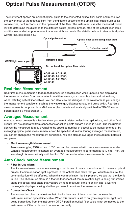
Optical pulse measurement
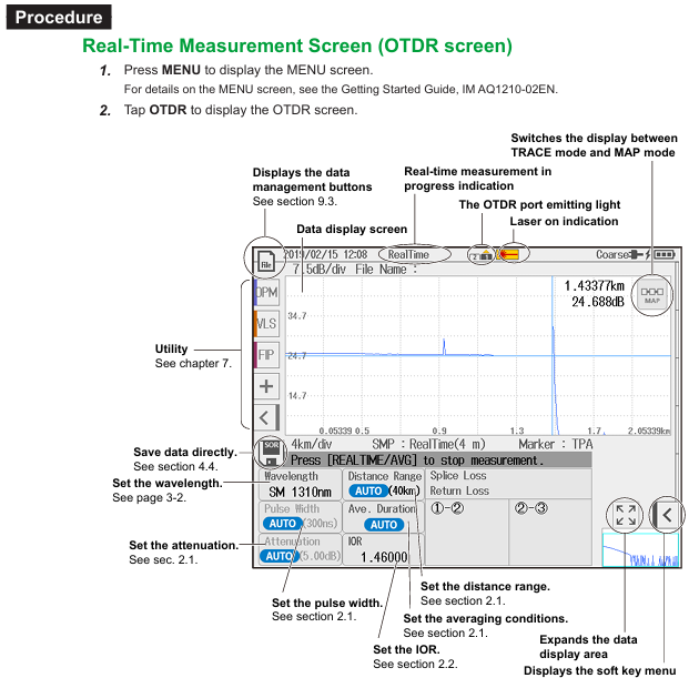
Real time measurement (TRACE mode): The waveform is updated and displayed in real time during measurement, and events such as fusion loss and return loss can be monitored in real time. It supports adjusting parameters such as wavelength and distance range. In MAP mode, it will automatically switch to TRACE mode.
Average measurement:
TRACE mode: Take the average of multiple measurements to display the waveform, suitable for detecting weak events masked by noise.
MAP mode: Automatically analyze OTDR waveform after average measurement, display various event types with icons, support preset qualified/unqualified judgment conditions, and identify results with colors.
Multi wavelength measurement: A single operation can measure two wavelengths, 1310nm and 1550nm (or 850nm and 1300nm). First measure 1310nm (or 850nm), and then automatically switch to another wavelength.
Automatic check before measurement:
In use fiber optic alarm: detect whether there is communication light in the tested fiber optic cable to avoid affecting normal communication. If there is, a pop-up window will prompt whether to continue.
Connection check: Check the connection status between the device and the fiber optic cable, and prevent the OTDR port from emitting light if it is not connected correctly.
The data shows
TRACE mode (waveform display): The horizontal axis represents distance and the vertical axis represents loss level. The waveform can be scaled and moved, and the detected loss or reflection events (such as connectors, fusion points, bending points, etc.) are marked on the waveform.
MAP mode (icon display): Use different icons to display the loss and reflection of events such as connection points, curved sections, and open ends, arranged in order from the measurement starting point to the open end, clearly presenting the event location and distance.
data analysis
Trace mode: manually measure the distance between two points, fusion loss, return loss, etc. using the cursor and markers, supporting multiple measurement methods such as 4-point and 6-point markers.
Event analysis: Automatically detect all events in the waveform, display event types (such as positive/negative fusion loss, reflection, bending loss, etc.) and analysis results (distance, loss value, etc.), support manual editing of events (insertion, deletion, adjustment of marker position).
Qualified/unqualified judgment: preset thresholds for fusion loss, return loss, loss per kilometer, total loss, etc., automatically judge whether the measured value meets the standard. In TRACE mode, qualified items are marked in green and unqualified items are marked in red, and in MAP mode, color coded icons are used.
File function: Supports saving measurement data (. SOR format, including waveform, condition, event list), reports (. PDF format), system settings (. CFG format), screenshots (. BMP/. JPG format), can be stored in built-in memory (approximately 256MB) or USB devices, supports file copying, deletion, renaming, and report generation (can choose to include measurement conditions, waveform, event list, etc.).
(2) Practical tool functions
Light Source: Generate specific wavelength measurement light (such as AQ1210A supporting 1310nm, 1550nm) for fiber loss measurement or identification, and can output continuous light (CW) or modulated light (such as 270Hz, 1kHz).
Visible light source (/VLS option): 650nm wavelength visible light, used for visual detection of fiber breakage and inspection of multi-core fiber cores, supporting CW and 2Hz modulation modes.
Optical power meter (/SPM//HPM//PPM option)
Standard optical power meter (/SPM): measuring fiber loss or optical signal power of communication equipment in the wavelength range of 800-1700nm.
High power optical power meter (/HPM): Maximum measurement+27dBm high power, used for loss measurement in high-power scenarios.
PON optical power meter (/PPM): Simultaneously measure the optical power of passive optical networks (PON) at three wavelengths of 1310nm/1490nm/1550nm.
Support logging function, record short-term optical power stability, generate CSV format log files, calculate maximum, minimum, and average values.
Power checker (/PC option): detects the presence and power value of communication light in the tested fiber through the OTDR port, measuring wavelengths covering commonly used bands such as 1310nm and 1490nm.
Fiber end face inspection (/FST option): Connect the designated fiber end face inspection probe of Yokogawa, capture the status of the fiber end face and display it on the device screen. The image can be saved, and qualified/unqualified judgments can be made for the end face contact area, cladding area, and fiber core area respectively (in accordance with IEC 61300-3-35 standard).
Optical switch control: Connect a compatible optical switch box (such as AQ3550, 1 × 12 port configuration) to switch the measurement optical path in optical pulse measurement, and automatically switch the target channel during multi-core measurement.
(3) Application Function
OTDR Smart Mapper: Automatically repeat average measurements with different pulse widths in a single operation, analyze events automatically after completion, support MAP/TRACE mode display, MAP mode presents line events with icons, and TRACE mode combines multiple pulse width waveforms to improve measurement accuracy.
Multi Fiber Project: Manage the conditions and core information required for multi-core fiber measurement through "projects", support real-time measurement, average measurement, optical power measurement, fiber inspection probe operation, automatically save the measurement results of each fiber core to the corresponding folder, and avoid missing measurements.
Auto Loss Test: Two devices act as light sources and optical power meters respectively, automatically switching between 1310nm and 1550nm wavelengths to measure fiber loss; A single device can test fiber loss through loopback mode (OTDR port connected to OPM port).
Multicore Loss Test: Two devices are set as the master (optical power meter) and slave (light source), respectively. The master creates a project and transmits it to the slave. Through signal transmission of fiber optic synchronization information, the multi-core fiber loss is measured in batches, and testing can be resumed from the next core after interruption.
Advanced Analysis
Multi trajectory analysis: Load up to 4 waveforms and display comparisons simultaneously, with the ability to adjust the vertical position of each waveform.
Bidirectional trajectory analysis: Combining waveforms measured from both ends of the fiber, accurately measure the fusion loss of fibers with different levels of backscattering.
Differential trajectory analysis: Load two waveforms, display their difference waveforms, and measure the loss and distance of the difference waveforms with markers.
Segment analysis: Set starting point (S) and ending point (E) markers, measure the specified segment return loss and total loss, and support setting reference point (B) to calculate return loss.
(4) System setup and maintenance
System settings: configurable power-saving mode (screen brightness, automatic sleep), network (LAN/WLAN, supports remote control and data transmission), language, startup interface (TRACE/MAP/settings information), screen color (Color 1/Color 2/Black and White), operation lock (PIN code restricts laser output, mode switching, etc.), expiration date (expiration prompt for calibration or device lock).
Troubleshooting and Updating: Provides common troubleshooting solutions, error code explanations, supports firmware updates via USB, can restore factory settings (divided into "Reset Settings" and "Reset Settings and Delete User Files"), supports adding optional feature licenses.
Maintenance and storage: Regular mechanical and operational inspections should be conducted, and high temperature, humidity, and vibration environments should be avoided during storage. The battery pack should be operated according to the specifications in the dedicated manual.
Safety and usage regulations
Safety warning: When measuring, the light source port will light up. Do not disconnect the connected fiber optic cable to avoid direct light to the eyes, which may cause visual damage; When the fiber optic cable is not connected, the light source port cover needs to be closed.
Operating standards: Before use, read the manual thoroughly and strictly follow the steps to set measurement conditions and perform measurements; USB devices should not be unplugged or powered off during reading and writing to avoid data damage; Fiber optic connections need to be checked for correctness to prevent equipment or fiber optic damage.
Trademark statement: Microsoft, Google Chrome, Adobe, Bluetooth, etc. are registered trademarks of corresponding companies, omitted from the manual ® And TM symbol.
Summary of Key Tables
(1) Wavelength of various types of light sources (partial)
Model measurement of light wavelength
AQ1210A 1310nm、1550nm
AQ1215A 1310nm、1550nm
AQ1210D 1310nm、1550nm、850nm、1300nm
AQ1210E 1310nm、1550nm、1625nm
(2) File format description
Extension Description
. SOR optical pulse measurement results (including measurement/analysis conditions, waveforms, and event lists)
. PDF report format for current waveform or saved files
CFG device system settings (devices, connections, etc.)
Screenshot of. BMP/. JPG devices
Multiple waveforms measured simultaneously by SOZ
The waveform measured by the SMP Smart Mapper function
(3) Meaning of warning symbols
Symbol+Text Meaning
Warning: Operations/conditions and preventive measures that may cause serious or fatal injuries
CAUTION prompts operations/conditions and preventive measures that may cause minor injuries, equipment damage, or data loss
Note: Important information for correct device operation
- YOKOGAWA
- Reliance
- ADVANCED
- SEW
- ProSoft
- WATLOW
- Kongsberg
- FANUC
- VSD
- DCS
- PLC
- man-machine
- Covid-19
- Energy and Gender
- Energy Access
- Renewable Integration
- Energy Subsidies
- Energy and Water
- Net zero emission
- Energy Security
- Critical Minerals
- A-B
- petroleum
- Mine scale
- Sewage treatment
- cement
- architecture
- Industrial information
- New energy
- Automobile market
- electricity
- Construction site
- HIMA
- ABB
- Rockwell
- Schneider Modicon
- Siemens
- xYCOM
- Yaskawa
- Woodward
- BOSCH Rexroth
- MOOG
- General Electric
- American NI
- Rolls-Royce
- CTI
- Honeywell
- EMERSON
- MAN
- GE
- TRICONEX
- Control Wave
- ALSTOM
- AMAT
- STUDER
- KONGSBERG
- MOTOROLA
- DANAHER MOTION
- Bentley
- Galil
- EATON
- MOLEX
- Triconex
- DEIF
- B&W
- ZYGO
- Aerotech
- DANFOSS
- KOLLMORGEN
- Beijer
- Endress+Hauser
- schneider
- Foxboro
- KB
- REXROTH
- YAMAHA
- Johnson
- Westinghouse
- WAGO
- TOSHIBA
- TEKTRONIX
- BENDER
- BMCM
- SMC
- HITACHI
- HIRSCHMANN
- XP POWER
- Baldor
- Meggitt
- SHINKAWA
- Other Brands
- UniOP
- KUKA
- IBA
- Beckhoff
-
LTI SC52.0040.0012.0000.0 - Servo Drive
-
Lti SC52.0040.0012.0000.0 - Servo Drive
-
Milton Industries LTI Tool By Milton LT1240 - 1/2" Drive Lugnut Remover
-
LTi Drives SO84.200.P030.0000.0-W - Servo Spindle Drive
-
LTI DRIVES LSP08-035-320-30-B0R1PY170 - Servo Motor
-
LTI DRIVES SE84.200.SC00.0001.0-W - Servo Drive
-
Lust CDE34.005.W2.2 - Lti Drives Controller
-
LTi SO84.012.0030.0011.2 - ServoOne Servo Drive
-
LTi Drives SO CM-P.0010.11.00.0 - Servo Drive Controller
-
LTi CDE34.017.W3.0 - Servo Drive
-
LTI Drives CDB32.004, C2.0,SH - Positioning Controller
-
LUST CM-CAN1 - LTi DRIVES Communication Module
-
LTi SO84.012.1030.0000.2 - Servo Drive
-
LTI MOOG CDE54.044 - PITCHMASTER FREQUENCY CONVERTER 181-01019
-
MOOG LTI 181-01019 CDE54.044 - PITCHMASTER FREQUENCY CONVERTER
-
Lust LTi Drives CDE34.010,D2.0 - Servo Drive Controller
-
LTI SO84.032.0003.0101.2 - Servo Drive
-
Seagate 9CC132-302 Harris LTI-CS IRT-34-0021-01 - Hard Drive 160GB
-
LTI SO84.032.0003.0001.2 - Servo Drive
-
LTI SO24.007.0070.0000.1 - SERVO CONTROLLER
-
LTi drive CDA32.003.C3.0.H05-01.PC1 - Servo Drive
-
LTI SO84.016.0030.0000.2 - SERVO CONTROLLER
-
LUST LTI CD A34.008,W1.4, BR - SERVO DRIVE
-
MOOG LTI 181-01019 CDE54.044 - PITCHMASTER FREQUENCY CONVERTER
-
LTI MOOG 181-01019 - PITCH Master Servo Drive CDE54.044
-
LTI SERVO ONE SO84.045.0030.0001.2-W - Drive
-
LUST LTi SO84.032.0040.0000.2 - SERVO ONE DRIVE
-
LTi Drives LSH-074-2-30-3 20/T1,G6.1M - SERVO MOTOR
-
LTI SO84.016.0000.0101.2 - servo drive
-
LTI SA54.0550.0033.0000.0 - Servo Drive
-
LTI SA54.0550.0033.0000.0 - Servo Drive
-
LTI LT 4850 - 3/8" Drive 3-Pc Twist Socket Transmission Drain Plug Removal System
-
LTI Tools LT4400-30 Lock Technology - 3/4" Twist Socket 1/2" Drive Lugnut Remover
-
LTI Tools LT-1400C - 1/2 Drive Wheel Torque Extension Tool
-
LTI Tools LT1250 - 1/2" Drive Dual Sided Socket Lug Nut Remover Tool
-
LTI SO84.032.0003.0101.2 - Servo Drive
-
LTI MOOG 181-01019 - PITCH Master Servo Drive CDE54.044
-
MOOG LTI 181-01019 CDE54.044 - PITCHMASTER FREQUENCY CONVERTER
-
MOOG LTI 181-01019 CDE54.044 - PITCHMASTER FREQUENCY CONVERTER
-
MOOG LTI 181-01019 CDE54.044 - PITCHMASTER FREQUENCY CONVERTER
-
LTI SA54.0550.0033.0000.0 - Servo Drive
-
LTI Tools LT-4800 - 7 Piece Twist Socket 3/8" Drive Oil Drain Plug Removal Set
-
LTI SA54.0550.0033.0000.0 - Servo Drive
-
LTI Drive SO24.007.00300000.0 - Servo Drive
-
LTI TOOLS LTI 1400-I - Drive Wheel Torque Extension
-
LTI Tools LT4400-3 - 3/4" 19mm Twist Socket 1/2" Drive Lugnut
-
LTI TOOLS LTI 1400-BB - Drive Wheel Torque Extension
-
LTI SO84.032.0003.0101.2 - Servo Drive
-
LTI Tools LT-4512 - 3/8" Drive 12mm Twist Socket
-
LTI MOTION Luster SO84.032.0003.0001.2 - Servo Drive
-
LTI Tool By Milton LT1600P - 1" Drive Torx Stick
-
LTI Lust VF1424L,HF,OP2,S56 - Variable Frequency Drive
-
LUST CDA32.004,C1.4,H08,B0 - SERVO DFRIVE CM-CAN1 Module
-
LTI SO84.045.0002.0001.2-W - Drive
-
LTI Lust VF1404M,C9,PT1,BR1 - Inverter Type VF1404M
-
LTI SA54.0550.0033.0000.0 - Servo Drive
-
LTI Tools LT-1400C - 1/2" Drive Wheel Torque Extension
-
Lust LTI DRiVES CDA32.006, C3.0, H09 - Variateur De Fr茅quence Frequency Inverter
-
LTI MOOG CDE54.044 - PITCH master SERVO DRIVE
-
LTI MOOG CDE54.044 - PITCH master SERVO DRIVE
-
LTI SO84.143.0020.0101.2-W - servo drive
-
LTI MOTION SC34.0200.0011.0000.0 - Servo drives
-
LTI SO84.032.0003.0001.2 - Servo Drive
-
LTI DRIVES GmbH MS100 - Assembly Set Mounting Kit
-
LTI SO84.032.0003.0001.2 - Servo Drive
-
LTI SO84.032.0003.0001.2 - Servo Drive
-
LTI MOTION SO84.032.0003.0101.2 - servo drive
-
LTI SO84.032.0003.0101.2 - Servo Drive
-
LTI MOOG CDE54.044 - PITCH master SERVO DRIVE
-
LTI MOTION CDE32.004.C2.4 - Servo drives
-
LTI CDD34.032锛學x.x锛孊R锛孭C1 - Servo Drive
-
Lust LTI DRiVES CDA32.006, C3.0, H09 - Inversor De Frecuencia Frequency Inverter
-
Lust SO84.008.0030.1000.0 - Servo One LTi Drive
-
LTI MOTION SO84.032.0003.0101.2 - Servo drives
-
LUST LTi CDA32.004,C1.4 - SERVO DRIVE
-
LTI MOOG CDE54.044 - PITCH Master SERVO DRIVE
-
LTI KEBA CDB32.004 C2.7, SH - PN: 08673530 Frequency Inverter
-
LTI Tools LT-1400C - 1/2" Drive Wheel Torque Extension
-
LTI LT1400-E - 1/2" Drive Wheel Torque Extension
-
LTI MOOG 181-01019 - PITCH master SERVO DRIVE CDE54.044
-
LTI LSN-097-0510-30-560/T1 - Actuator Motor
-
LTI Tools LT 4800 - 7 Piece 3/8" Drive Twist Socket Oil Drain Plug Removal System
-
LTI DRIVES GmbH MS100 - MONTAGESET Assembly Set Mounting Kit
-
Lti SC52.0040.0012.0000.0 - Servo Drive
-
LTI DRIVES GmbH MS100 - Juego De Montaje Assembly Set Mounting Kit
-
LTi DSM4-14.2-21R83-200 - Drives servomoteur Servo Motor
-
MOOG CDE 54.044.GDA - Pitch Master Industrielle Turbine Lti Drive
-
LTI SO24.004.0030.1000.0 - Servo Drive Controller
-
Lti MOOG CDE54.044 - Pitch Master Servo Drive
-
Lust LTI DRiVES CDA32.006, C3.0, H09 - Inverter
-
LTI MOTION GMBH CDB34.006,W3.0,PC1,H39 - Frequency inverter
-
LTI SO84.032.0003.0001.2 - Servo Drive
-
MOOG CDE 54.044.D - Pitch Master Industrielle Turbine Lti Drive
-
LTI TOOLS LT-1460 - 1/2" DRIVE WHEEL TORQUE EXTENSION KIT 5 PIECE SET
-
Lust Cdb32.003, C2.4 - Lti Drives Servoregulador Frecuencia Servo Controller Inverter
-
Lust LTI DRIVES CDA32.006, C3.0, H09 - Frequency Inverter
-
Lust Lti SO82.004.0030.0000.2 - Servo Drive
-
LTI MOTION SC34.0200.0011.0000.0-SL - Servo drives
-
LTI MOTION SA54.0075.0033.0000.0 - Servo drives
-
LTI MOTION SC32.0075.1011.0000.0 - Servo drives
-
LTI Servo-One Junior SO22.006.0080.1000.0 - Servo Controller Servoregler
-
LUST CDA32.004, C1.4, H08, B0 - Servo Drive & LTI CM-CAN1 Module
-
LTI DRIVES LSP08-035-320-30-B0R1PY170 - Servo Motor
-
LUST LTI CDA32.004,C1.4.H08.B0 - SERVO CONTROLLER DRIVES
-
LUST LTi DRiVES CDS44.072LC1.2 - Servo Drive
-
Lti Servo-One Junior SO22.006.0082.1000.0 - Servo Controller Servoregler
-
LUST CDA32.008,C2.0,HF - Lti DRIVES Spindle Drive Inverter
-
LTI SO22.003.0082.0000.0 - Servo Drives One junior Servo Controller Servoregler
-
Lust Lti Drives CM-CAN1 - Communication Module
-
LUST Lti Drives Vf1202s, G8, I6 - Frequency Inverter Drive
-
LTI DRIVES BR-090.03.540.UR.H38 - Bremswiderstand Brake Resistor
-
LTi DRIVES PM-E40.2DRA054P - Wind Turbine Pitch Control Inverter
-
LTi Drives GmbH br-110.01.540-UR - Brake Resistor
-
LTI Drives LSN-097-0960-30-0560/T1,S4,B - Servo Motor
-
LUST CDA34.006.C2.0 - LTI Drives Servoregler
-
LUST LTI DRIVES SERVO ONE JUNIOR SO24.002.0020.0000.1 - Servo Drive Controller
-
LTI MOTION SO84.032.0003.0001.2 - Servo drives
-
LTI DDTD750V2-120 - IBOP ACTUATOR CYLINDER FOR TOP DRIVE
-
LTI CDE32.004, C2.4 - SERVO DRIVE
-
LUST LTI DRIVES CDD34.017 W3.4PC1 - Servo Drive Controller
-
LTI CDA3208,C3,0,HF - AC SERVO DRIVE
-
LUST LTI DRIVES LSH-074-3-30-560/T1,G6.1S - SERVO MOTOR
-
LUST Lti CDB32.004.C2.4.SH - AC Servo Drive
-
LTi CDA32.006, C3.0, H09 - Servo Drive
-
LTI SO22.003.0010.0000.0 - Servo Drive Servo one junior Servoregler Controller
-
LTi Drives DSM4-14.2-21R83-200 - Servo Motor
-
LUST Lti Drives Lsh-097-1-30-560/T1, 1R - Servomotor
-
LTI 1237 - 7 Piece 1/2" Drive Flip Socket Set

K-JIANG

Add: Jimei North Road, Jimei District, Xiamen, Fujian, China
Tell:+86-15305925923