
K-WANG


Yokogawa DLM5000HD series high-definition oscilloscope
Yokogawa DLM5000HD series high-definition oscilloscope
Document Overview
This document is the user manual (2nd edition, released in July 2024) for Yokogawa Electric's DLM5034HD, DLM5038HD, DLM5054HD, and DLM5058HD series high-definition oscilloscopes. It aims to guide users in correctly operating this series of oscilloscopes, covering core content such as instrument usage, function settings, and maintenance. It also provides a list of relevant documents and contact information, and the manual content may change due to instrument performance and function upgrades. The latest version should refer to the official website.
Basic information and precautions
(1) Documents and Contact
Related documents: In addition to this user manual (IM DLM5058HD-02EN), it also includes an introductory guide (including operating precautions, troubleshooting, etc.), an operating guide (basic operating steps), a download manual request document, Chinese specific documents, European language safety manuals, etc. Some manuals need to be downloaded from the official website.
Global Contact: Document number PIM 113-01Z2 provides contact information for Yokogawa offices worldwide to facilitate users in obtaining technical support.
(2) Important precautions
Content changes: The manual content may be changed without prior notice, and the latest version should be viewed through the official website.
Interface differences: The illustrations in the manual may differ from the actual screen display.
Copyright protection: It is strictly prohibited to copy or reproduce all or part of the content of the manual without permission from Yokogawa.
Software Disclaimer: The TCP/IP software and related documentation of the product are developed based on BSD network software authorized by the Board of Directors of the University of California.
Trademark Description: Microsoft, Windows, Adobe, Acrobat, etc. are registered trademarks of corresponding companies, DLM is a registered trademark of Yokogawa Electric, omitted from the manual ® And TM symbol.
Instrument basic settings
(1) Model and symbol rules
Model Differences: The manual mainly explains the operation of 8-channel models, and there are differences in channel settings for different models (4-channel/8-channel), such as 8-channel models supporting CH1-CH8 and 4-channel models only supporting CH1-CH4.
Symbol differentiation: The prefix "k" represents 1000 (e.g. 100 kS/s, sampling rate), and "K" represents 1024 (e.g. 720 KB, file size); Bold characters in the operation steps represent panel buttons, soft keys, and screen menu options.
(2) Classification of safety warnings
Warning: Indicate operations or situations that may cause serious or fatal injuries, as well as preventive measures.
CAUTION: Indicates operations or situations that may cause minor injury, instrument damage, or data loss, as well as preventive measures, and includes French comparative instructions.
Note: Important information for the correct operation of the instrument.
Core Function Operation Guide
(1) Vertical and horizontal control
Analog signal channel configuration (CH menu)
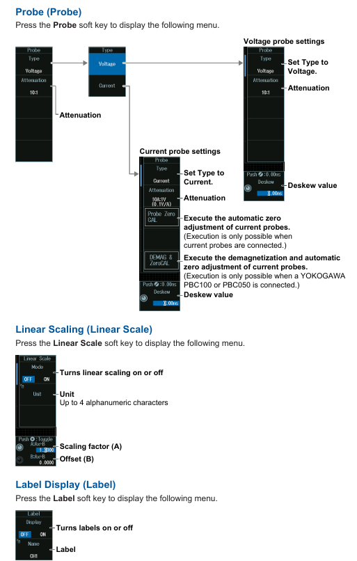
Basic settings: Can control waveform display switch, input coupling (AC/DC/DC50), probe parameters (attenuation ratio, etc.), waveform inversion, linear scaling, label display, bandwidth limitation, offset, etc. When the input coupling is AC, low-frequency signals or low-frequency components may be attenuated, and attention should be paid to the integrity of signal monitoring; The DC50 mode displays the DC and AC components of the signal through 50 Ω.
Safety restrictions: The maximum voltage for a 1M Ω input is 300 Vrms or 400 Vpeak (100kHz and below), and for a 50 Ω input, the maximum voltage is 5 Vrms or 10 Vpeak. Overvoltage may damage the input part; When changing the input coupling, attention should be paid to the actual coupling state changes during the next waveform acquisition.
Offset cancellation: The offset cancellation function can be turned on/off through the system configuration in the UTILITY menu, and the offset setting is applicable to all input coupling modes. When the probe attenuation changes, the vertical scale will be scaled according to the new attenuation ratio. When the offset value exceeds the range, it will be automatically adjusted to the maximum value. After restoring the original vertical scale, the offset value will be restored.
Channel information copying (CH UTIL menu): The analog signal input settings of one channel can be copied to other channels by selecting the source channel and target channel. The channel ranges that can be copied for 8-channel and 4-channel models are CH1-CH8 and CH1-CH4, respectively. When copying, the source channel is light gray and cannot be selected separately. When selecting all channels collectively, although the source channel is checked, copying will not be performed.
Logic signal setting (LOGIC menu)
Basic functions: Control logic signal waveform display switch, bit setting (display switch, label, threshold level, noise suppression, etc.), bus display (switch, bit allocation, label, format, etc.), bit and bus display sequence, status display (switch, clock source, polarity, etc.), offset correction.
Collection restriction: When the record length in the ACQUIRE menu is set to the maximum value, the waveforms of LOGIC ports C (C0-C7) and D (D0-D7) cannot be collected.
Threshold and noise: The 701989 logic probe can set the threshold type (All/Each), and selecting the preset threshold will automatically configure it. After changing it, the preset will become "Userdef"; The noise suppression function is only available for probe 701989, and the level and noise suppression in the bit setting will be synchronized to the setting when the trigger source is Logic.
Vertical axis setting (SCALE/POSITION knob)
Analog signal: Press the CH1-CH8 keys to select the channel, adjust the vertical scale with the SCALE knob, and press the knob to enter FINE mode for high-precision adjustment; Adjust the vertical position with the POSITION knob, press it to set the position to 0 div. When adjusting, the corresponding channel information display area will temporarily display the relevant values, and there will be an out of range prompt.
Logic signal: Press the LOGIC key to control the display size of the logic signal on the SCALE knob, adjust the vertical position on the POSITION knob, and the LED will display the symbol color of the corresponding channel or logic signal.
All on/off (CH UTIL menu): It can collectively display or hide all analog signal channel waveforms, and logic signals do not have this collective control function.
Horizontal scale setting (TIME/DIV knob): Adjust the sensitivity of the horizontal scale, and temporarily display the time scale value and recording length in the upper right corner of the screen when controlling; ◄ POSITION ► Rotate the knob to adjust the horizontal position of the waveform, synchronously move the trigger position, press to set the trigger position to 50%, and adjust the waveform display in real-time during collection and operation.
(2) Trigger function
Trigger mode and hold time (MODE menu)
Trigger modes: including Auto (automatically updates waveform when triggering conditions are met or timeout occurs, with timeout of 100ms or the larger value of 10 time axis scales, and enables scrolling mode when the time axis exceeds the threshold), Auto Level (automatically sets the trigger level to the center value of the trigger source amplitude and triggers when timeout is not triggered), Normal (updates only when triggering conditions are met), N Single (stops and displays after collecting a specified number of signals), Single (presses the SINGLE button on the panel, collects waveform once and stops after triggering).
Holding time: Set through the Holdoff soft key to prevent accidental triggering, adjustable through jog shuttle or on-screen numeric keypad.
Collection Count: In N Count mode, the number of collected waveforms can be set, which can also be configured through jog shuttle or on-screen numeric keypad.
Trigger position and delay (◄ POSITION ►/DELAY key)
Trigger position: ◄ POSITION ► knob adjustment, temporary display of position value at the top of the screen during control, can also be set when no waveform is collected.
Trigger delay: After pressing the DELAY key to enable it, adjust the delay value with the ◄ POSITION ► knob, and the screen will temporarily display at the top. Press the DELAY key again to switch back to the trigger position setting; The delay cancellation function is enabled/disabled through the UTILITY menu system configuration. When enabled, the time measurement is based on the trigger position of 0s (no delay applied), and when disabled, the trigger point is 0s (delay applied), and the delay value is not affected by changes in the horizontal scale.
Various trigger settings (EDGE/ENHANCED/B TRIG menu)
Edge trigger (EDGE menu): Select the trigger source (CH1-CH8/Logic/EXT/LINE), set the trigger slope, high-frequency suppression, noise suppression, and trigger level. The settings for different sources (such as Logic requiring source position, EXT requiring probe attenuation and input range) may vary; LINE source only triggers rising edge.
Enhanced Trigger (ENHANCED Menu): Includes multiple types, such as multi edge trigger OR (select trigger source channel and slope, set trigger level for each channel, high-frequency/noise suppression), multi input mode trigger (set clock source, trigger source mode and combination conditions, time conditions, etc.), pulse width trigger (select source, polarity, high-frequency/noise suppression, trigger level, set time conditions and reference time, trigger when pulse width and reference time relationship are met), as well as rise/fall time trigger, runt signal trigger, timeout trigger, window trigger, etc. Some trigger types (such as bus signal trigger) are optional functions.
Combination trigger (B TRIG menu): Set the combination method of trigger A and trigger B (OFF/A Delay B/A to B (N)). In A Delay B mode, trigger A after it satisfies the specified time delay, and trigger B when it satisfies the specified time delay; In the A to B (N) mode, when A is triggered and B is triggered N times, it can be triggered, and both A and B can choose multiple types of edge triggering or enhanced triggering (such as bus signal triggering). However, when B is triggered through a window, the time limit is fixed at None, and the triggering condition for the mode without a clock source cannot be selected as True/False.
FORCE TRIG: Press the SHIFT+B TRIG key to forcibly trigger even if the triggering conditions are not met, and it can also be operated through the screen menu.
Trigger linkage function
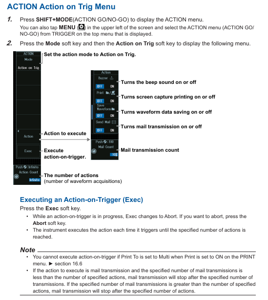
Trigger action (ACTION menu): Press the SHIFT+MODE key to enter. In Action on Trig mode, you can set the action to be executed when triggered (beeping, printing, waveform saving, email sending), the number of actions, and the number of emails to be sent. Press the Execute key during execution, and press the Abort key to terminate the process; Please note that when printing is set to ON and Print To is set to Multi, it cannot be executed. The number of emails sent is limited by the smaller of the number of actions and the number of times it is set.
GO/NO-GO judgment (ACTION menu): In Go/GO AND/OR mode, set the number of actions, NO-GO times, and reference conditions (rectangular area/waveform area/polygon area/parameter range). When executing the judgment, press the Execute key and stop when the number of actions or NO-GO times is reached; The source waveforms are different, and there are differences in the available reference range types, such as Logic being unable to select rectangular and polygonal areas.
(3) Waveform acquisition
Acquisition condition settings (ACQUIRE menu): Control record length, high-resolution mode switch, acquisition mode (Normal/Convert/Average), sampling mode (Real time/Interpolation/Reactive), trigger mode, acquisition count (Normal/Convert mode), attenuation constant and average frequency (Average mode). Different acquisition modes are suitable for different scenarios, such as Envelope mode displaying waveform envelope and Average mode displaying average waveform; Repetitive sampling mode is not suitable for situations where the Logic trigger source or record length is ≥ 2.5M points; The recording length affects the sampling rate and observation duration. Long recording length may increase the calculation and measurement time, and the range of recording length corresponding to a single acquisition varies for different memory option models.
Waveform acquisition control (RUN/STOP/SINGLE key): Press the RUN/STOP key to start/stop the acquisition, which is equivalent to the SINGLE key when it matches the length of a single acquisition record; After triggering with the SINGLE key, the waveform is collected once and stopped. The triggering mode is automatically set to single shot, and the collection process can be terminated by pressing the RUN/STOP key.
(4) Display function
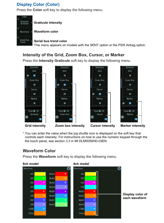
Display condition settings (PLAY menu): Control display format (Auto/Single/Dual, auto split or fixed split), display interpolation (OFF/nSine/Line/Pulse, different modes apply different signal types, such as Logic signal fixed Pulse interpolation), grid (Dot Grid/Line Grid, etc.), scale value display switch, waveform mapping (8/4 channel models map channels to screen areas, Auto mode automatically assigns, Manual mode manually sets), color (waveform, serial bus trend color, grid, zoom box intensity, etc.), waveform intensity (adjusted through jog shuttle, accumulation time can also be set in accumulation mode).
Accumulate function (Display menu): Select the Accumulate soft key to OFF (display single acquisition waveform), Intensity (use intensity to represent accumulated frequency), Color (use color to represent accumulated frequency, with 15 levels of color ranging from low to high as blue-green yellow red white), and the accumulation time can be adjusted; During the accumulation process, automatic parameter measurement and GO/NO-GO determination are based on the latest waveform. Accumulation stops when the acquisition is stopped, and clears and restarts when the acquisition is restarted. When changing the display format, the accumulation will clear and restart, and the latest waveform will be displayed when the accumulation is stopped.
SNAP SHOT/CLEAR TRACE: Press the SNAP SHOT key to keep the current waveform as a white snapshot on the screen until the trace is cleared; Press the CLEAR TRACE key to clear all screen waveforms. During the acquisition process, clearing the trace will clear the historical waveforms and restart the acquisition.
Backlight adjustment (UTILITY menu): In the system configuration, brightness can be adjusted, backlight automatic off time can be set, automatic shutdown can be turned on/off, and backlight can be manually turned off (press any key to restore) to meet the visual needs and power consumption control of different usage environments.
Transparent display on the operation screen (UTILITY menu): After enabling it in the system configuration, the menu and dialog box can be set to display transparently. It can be operated while viewing the background waveform. The transparency level is 1-5 (the higher the level, the clearer the background), and the transparency mode can also be quickly switched on and off through the icon in the bottom left corner of the screen.
(5) XY waveform display
XY waveform display settings (X-Y menu): Control the XY waveform display switch, X/Y-axis source waveform (8-channel model XY1-XY2 corresponds to CH1-CH4/Math1-Math4, XY3-XY4 corresponds to CH5-CHO/Math5-Math8; 4-channel models XY1-XY2 correspond to CH1-CH4/Math1-Math4), display settings, measurement source window (Main/Zoom1/Zoom2), display range (starting/ending), time-domain waveform display switch, split screen display switch, up to 4 XY waveforms can be displayed. To switch the settings menu, press the XY soft key.
Cursor measurement and area calculation (X-Y menu): Set the vertical/horizontal cursor position in cursor mode to measure parameters such as Δ X and Δ Y; Select the area determination method (Close/Loop/Rapidoid sum/Triangle sum) and polarity (CW/CCW, clockwise/counterclockwise is the positive direction) in Integ mode, and calculate the XY waveform area.
(6) Calculation and reference waveform
Calculation mode setting (MATH/REF menu): Select the calculation or reference waveform (8-channel model Math/Ref1 Math/Ref8, 4-channel model Math/Ref1 Math/Ref4), set the mode to OFF (not displayed), Math (displays calculation waveform), Ref (displays reference waveform); It should be noted that the calculation waveform is not displayed during single-mode acquisition, and the recording length is set to the maximum value, Math/Ref2、 4. 6 and 8 cannot be used.
Calculation function (Math mode): Supports addition, subtraction, multiplication (selecting source waveform), filtering function (delay/moving average/IIR low-pass/high pass, setting delay time, weighting points, filtering order and cutoff frequency, etc.), integration (selecting source waveform, initial point), counting operation (edge counting/rotation counting, setting polarity, trigger level, threshold, etc.), user-defined calculation (optional parameters and operators, setting labels, units, scaling, etc.). The selection of source waveforms for different calculation functions is limited by specific ranges, such as CH1-CH4 for 8-channel model Math1.
Reference waveform loading (Ref mode): Load reference waveforms (source waveforms for 8-channel model Ref1 are CH1-CH4/Math2-Math4, etc.), set labels, display reference waveform information, and vertical position. The selection range of reference waveform source waveforms varies depending on the model and channel number.
(7) FFT analysis
FFT waveform display (FFT menu): Control the FFT waveform display switch, analyze the source waveform (8-channel models CH1-CH8/Math1-Math8, 4-channel models CH1-CH4/Math1-Math4), FFT conditions (spectrum type/subtype, window, mode, unit, etc., some types require user-defined calculation options), analysis range (Main/Zoom1/Zoom2), vertical/horizontal scale values (Auto/Manual, manually set center/sensitivity or left and right boundaries/center and span), FFT point count, display up to 4 FFT waveforms (4-channel models up to 2), switch settings menu by pressing the FFT soft key.
FFT waveform measurement (FFT menu): Select the measurement mode (Marker/Peak/Parameter) from the Measure Setup menu, and set the measurement item and cursor position in Marker mode; Peak mode setting list number, peak detection threshold, peak valley difference, measurement range, displaying peak frequency and amplitude; Parameter mode (only available for specific spectrum types) enables/disables overall value measurement, and the number of FFT points and display points may be adjusted due to the length of the display record. When the number of points is insufficient, data will be extracted, and when the number of points is too large, the adaptation will be reduced.
(8) Measurement function
Cursor measurement (CURSOR menu): Supports Δ T (measuring time, selecting source waveform, measurement item, cursor jump, cursor position), Δ V (measuring vertical value, selecting source waveform, measurement item, cursor position), Δ T&Δ V (simultaneously measuring time and vertical value), Marker (marking cursor, selecting display format, source waveform and measurement item, cursor jump, position), Degree (angle cursor, selecting source waveform, measurement item, reference setting, cursor jump, position). The selection range of different cursor types of source waveforms varies depending on the model and function, such as Δ V cursor only supporting CH/Math channels.
Automatic parameter measurement (MEASURE menu): After enabling, select the measurement source waveform and measurement items (such as Max/Min/P-P/Freq, etc.), measurement position indication, reference level, measurement source window (Main/Zoom1/Zoom2), measurement range (starting/ending point), statistical processing (Continuous/Cycle/History mode, processing statistical data of automatic measurement values, such as trend chart, histogram, list display), enhanced parameter measurement (measuring and calculating parameters in two regions, setting expressions, labels, units, etc.), measurement item display position can be selected through the Indicator soft key and indicated by the cursor, reference level can be set near/far/middle value, etc., and some functions in scrolling mode (such as statistical processing, serial display, etc.) During bus analysis, automatic measurement values may not be displayed and will resume after stopping data collection.
(9) Waveform scaling
Waveform scaling (ZOOM1/ZOOM2 menu): Control the scaling switch, scaling source waveform, display format, scaling position, main window display mode, scaling factor, automatic scrolling, up to 2 scaling positions. When the ZOOM1/ZOOM2 keys are on, the ZOOM knob controls the corresponding window waveform. Press the rotary knob to enter FINE mode for high-precision adjustment; Automatic scrolling allows setting the scrolling direction and speed, and the zoom position can be adjusted through the jog shuttle or on-screen numeric keypad. When two zoom windows are opened simultaneously, the zoom position can be linked and controlled.
Vertical Zoom (ZOOM menu): The Vertical Zoom soft key is used to reset the vertical zoom (collectively initialize the zoom position and multiplier of all waveforms), the source waveform, and the vertical zoom position and multiplier. A single waveform can be initialized using the RESET key, and the vertical zoom position and multiplier can be adjusted using the jog shuttle. Press the SET key to switch adjustment options.
(10) Waveform search
Basic search operation (SEARCH menu): Set the search type (Edge/Attention/Pulse Width/Timeout), search criteria (corresponding to the type of source waveform, slope, level, mode, etc.), search range (starting/ending point), search skip (OFF/Holdoff/Precision, skipping the specified time or number of searches), detect waveform display (marker display, result window selection), perform search, detect point number and zoom position, display configuration during search is similar to ZOOM menu, search results are displayed in the center of the result window (Zoom1/ZOOM2), and waveform acquisition or cumulative waveform search cannot be performed during the search process.
Various search settings: Edge search (selecting source waveform, slope, trigger level and lag), Pattern search (selecting clock source, trigger source pattern and combination conditions, time conditions, etc.), Pulse Width search (selecting source, polarity, time conditions and reference time), Timeout search (selecting source, polarity, timeout time). The selection range and condition settings for different search types of source waveforms vary. For example, when Pattern search does not have a clock source, all CH and Logic signal patterns need to be set.
(11) Serial Bus Signal Analysis and Search (Serial BUS menu, optional function)
Supports analysis and search of FlexRay, CAN, CAN FD, LIN, CXPI, SENT, PSI5 Airbag, UART, I2C, SPI, and user-defined serial bus signals. The settings for each bus type include:
Bus settings: Automatic settings (configuring source waveform, bit rate, level, hysteresis, etc.) or manual settings (bit rate, sampling points, channel allocation, etc.). Automatic settings may not be able to adapt to some input signals, and cannot be automatically set when the source waveform is a Math channel.
Decoding display: Set the display format (Hex/Label/Symbol, etc. Symbol requires loading physical values/symbol definition files) and display position (Auto/Manual).
List/Trend Display: The list displays the analysis results (serial number, ID, data, etc.), and can be set in terms of list size, display position, zoom link, and filtering criteria; Trend display (supported by some buses) with settings for display sources, data items, cursor measurement, auto scaling, etc.
Search settings: Select the search type (such as frame start, error, ID/data, etc.), search criteria (frame format, ID mode, data range, etc.), perform the search, detect point numbers and zoom positions. The search results are displayed in the results window, and the search criteria and frame structure adaptation for different buses are different. For example, CAN FD supports ISO/non ISO standards, and SENT supports different version formats.
(12) Other functions
Waveform Histogram Display (HISTOGRAM Menu): Control the histogram display switch, source waveform, histogram type (amplitude/time/parameter), measurement parameters (statistical histogram mean, standard deviation, etc.), and visually display the distribution of waveform parameters.
Power Analysis (POWER ANALYSIS menu, optional function): Supports safe working area analysis, harmonic analysis, Joule integration measurement, switch loss analysis, power measurement, setting analysis type, source waveform, measurement parameters (such as harmonic frequency, integration time, etc.), suitable for special analysis of power related signals.
History waveform display and search (History menu): Control the history waveform display switch, display quantity, and search history waveforms (set search conditions and execute search), allowing for retrospective viewing of previously collected waveform data, facilitating fault diagnosis and signal change analysis.
Print and screenshot (PRINT/SAVE menu): Built in printer (optional) for paper loading and printing operations, USB/network printer printing, screenshot saving to files, and simultaneous output of print and screenshot data to multiple targets, meeting data recording and sharing needs.
Data saving and loading (SAVE/LOAD menu): Connect a USB storage device to save waveform data, set data, and other types of data (such as histograms, trends, etc.), load various saved data, perform file operations (new/delete/rename, etc.), facilitate data backup and instrument status recovery.
Ethernet communication (Ethernet menu): Connect to the network, configure TCP/IP settings, FTP server (PC access instrument), SMTP client (email sending), FTP client (connect to network drive), network printer configuration, SNTP time synchronization, realize network remote control and data transmission of the instrument.
Synchronization operation (DLMsync menu, optional function): Start/stop synchronization operation of multiple instruments, correct sampling deviation between units, and improve the accuracy of multi device collaborative testing.
Other operations (UTILITY menu): Change menu, message and USB keyboard language, set click sound, measure font size and display line count, view setting information, use the instrument as a USB storage device, IEEE 1588 clock synchronization, adapt to different user operating habits and system integration requirements.
- YOKOGAWA
- Reliance
- ADVANCED
- SEW
- ProSoft
- WATLOW
- Kongsberg
- FANUC
- VSD
- DCS
- PLC
- man-machine
- Covid-19
- Energy and Gender
- Energy Access
- Renewable Integration
- Energy Subsidies
- Energy and Water
- Net zero emission
- Energy Security
- Critical Minerals
- A-B
- petroleum
- Mine scale
- Sewage treatment
- cement
- architecture
- Industrial information
- New energy
- Automobile market
- electricity
- Construction site
- HIMA
- ABB
- Rockwell
- Schneider Modicon
- Siemens
- xYCOM
- Yaskawa
- Woodward
- BOSCH Rexroth
- MOOG
- General Electric
- American NI
- Rolls-Royce
- CTI
- Honeywell
- EMERSON
- MAN
- GE
- TRICONEX
- Control Wave
- ALSTOM
- AMAT
- STUDER
- KONGSBERG
- MOTOROLA
- DANAHER MOTION
- Bentley
- Galil
- EATON
- MOLEX
- Triconex
- DEIF
- B&W
- ZYGO
- Aerotech
- DANFOSS
- KOLLMORGEN
- Beijer
- Endress+Hauser
- schneider
- Foxboro
- KB
- REXROTH
- YAMAHA
- Johnson
- Westinghouse
- WAGO
- TOSHIBA
- TEKTRONIX
- BENDER
- BMCM
- SMC
- HITACHI
- HIRSCHMANN
- XP POWER
- Baldor
- Meggitt
- SHINKAWA
- Other Brands
- UniOP
- KUKA
- IBA
- Beckhoff
-
LTI SC52.0040.0012.0000.0 - Servo Drive
-
Lti SC52.0040.0012.0000.0 - Servo Drive
-
Milton Industries LTI Tool By Milton LT1240 - 1/2" Drive Lugnut Remover
-
LTi Drives SO84.200.P030.0000.0-W - Servo Spindle Drive
-
LTI DRIVES LSP08-035-320-30-B0R1PY170 - Servo Motor
-
LTI DRIVES SE84.200.SC00.0001.0-W - Servo Drive
-
Lust CDE34.005.W2.2 - Lti Drives Controller
-
LTi SO84.012.0030.0011.2 - ServoOne Servo Drive
-
LTi Drives SO CM-P.0010.11.00.0 - Servo Drive Controller
-
LTi CDE34.017.W3.0 - Servo Drive
-
LTI Drives CDB32.004, C2.0,SH - Positioning Controller
-
LUST CM-CAN1 - LTi DRIVES Communication Module
-
LTi SO84.012.1030.0000.2 - Servo Drive
-
LTI MOOG CDE54.044 - PITCHMASTER FREQUENCY CONVERTER 181-01019
-
MOOG LTI 181-01019 CDE54.044 - PITCHMASTER FREQUENCY CONVERTER
-
Lust LTi Drives CDE34.010,D2.0 - Servo Drive Controller
-
LTI SO84.032.0003.0101.2 - Servo Drive
-
Seagate 9CC132-302 Harris LTI-CS IRT-34-0021-01 - Hard Drive 160GB
-
LTI SO84.032.0003.0001.2 - Servo Drive
-
LTI SO24.007.0070.0000.1 - SERVO CONTROLLER
-
LTi drive CDA32.003.C3.0.H05-01.PC1 - Servo Drive
-
LTI SO84.016.0030.0000.2 - SERVO CONTROLLER
-
LUST LTI CD A34.008,W1.4, BR - SERVO DRIVE
-
MOOG LTI 181-01019 CDE54.044 - PITCHMASTER FREQUENCY CONVERTER
-
LTI MOOG 181-01019 - PITCH Master Servo Drive CDE54.044
-
LTI SERVO ONE SO84.045.0030.0001.2-W - Drive
-
LUST LTi SO84.032.0040.0000.2 - SERVO ONE DRIVE
-
LTi Drives LSH-074-2-30-3 20/T1,G6.1M - SERVO MOTOR
-
LTI SO84.016.0000.0101.2 - servo drive
-
LTI SA54.0550.0033.0000.0 - Servo Drive
-
LTI SA54.0550.0033.0000.0 - Servo Drive
-
LTI LT 4850 - 3/8" Drive 3-Pc Twist Socket Transmission Drain Plug Removal System
-
LTI Tools LT4400-30 Lock Technology - 3/4" Twist Socket 1/2" Drive Lugnut Remover
-
LTI Tools LT-1400C - 1/2 Drive Wheel Torque Extension Tool
-
LTI Tools LT1250 - 1/2" Drive Dual Sided Socket Lug Nut Remover Tool
-
LTI SO84.032.0003.0101.2 - Servo Drive
-
LTI MOOG 181-01019 - PITCH Master Servo Drive CDE54.044
-
MOOG LTI 181-01019 CDE54.044 - PITCHMASTER FREQUENCY CONVERTER
-
MOOG LTI 181-01019 CDE54.044 - PITCHMASTER FREQUENCY CONVERTER
-
MOOG LTI 181-01019 CDE54.044 - PITCHMASTER FREQUENCY CONVERTER
-
LTI SA54.0550.0033.0000.0 - Servo Drive
-
LTI Tools LT-4800 - 7 Piece Twist Socket 3/8" Drive Oil Drain Plug Removal Set
-
LTI SA54.0550.0033.0000.0 - Servo Drive
-
LTI Drive SO24.007.00300000.0 - Servo Drive
-
LTI TOOLS LTI 1400-I - Drive Wheel Torque Extension
-
LTI Tools LT4400-3 - 3/4" 19mm Twist Socket 1/2" Drive Lugnut
-
LTI TOOLS LTI 1400-BB - Drive Wheel Torque Extension
-
LTI SO84.032.0003.0101.2 - Servo Drive
-
LTI Tools LT-4512 - 3/8" Drive 12mm Twist Socket
-
LTI MOTION Luster SO84.032.0003.0001.2 - Servo Drive
-
LTI Tool By Milton LT1600P - 1" Drive Torx Stick
-
LTI Lust VF1424L,HF,OP2,S56 - Variable Frequency Drive
-
LUST CDA32.004,C1.4,H08,B0 - SERVO DFRIVE CM-CAN1 Module
-
LTI SO84.045.0002.0001.2-W - Drive
-
LTI Lust VF1404M,C9,PT1,BR1 - Inverter Type VF1404M
-
LTI SA54.0550.0033.0000.0 - Servo Drive
-
LTI Tools LT-1400C - 1/2" Drive Wheel Torque Extension
-
Lust LTI DRiVES CDA32.006, C3.0, H09 - Variateur De Fr茅quence Frequency Inverter
-
LTI MOOG CDE54.044 - PITCH master SERVO DRIVE
-
LTI MOOG CDE54.044 - PITCH master SERVO DRIVE
-
LTI SO84.143.0020.0101.2-W - servo drive
-
LTI MOTION SC34.0200.0011.0000.0 - Servo drives
-
LTI SO84.032.0003.0001.2 - Servo Drive
-
LTI DRIVES GmbH MS100 - Assembly Set Mounting Kit
-
LTI SO84.032.0003.0001.2 - Servo Drive
-
LTI SO84.032.0003.0001.2 - Servo Drive
-
LTI MOTION SO84.032.0003.0101.2 - servo drive
-
LTI SO84.032.0003.0101.2 - Servo Drive
-
LTI MOOG CDE54.044 - PITCH master SERVO DRIVE
-
LTI MOTION CDE32.004.C2.4 - Servo drives
-
LTI CDD34.032锛學x.x锛孊R锛孭C1 - Servo Drive
-
Lust LTI DRiVES CDA32.006, C3.0, H09 - Inversor De Frecuencia Frequency Inverter
-
Lust SO84.008.0030.1000.0 - Servo One LTi Drive
-
LTI MOTION SO84.032.0003.0101.2 - Servo drives
-
LUST LTi CDA32.004,C1.4 - SERVO DRIVE
-
LTI MOOG CDE54.044 - PITCH Master SERVO DRIVE
-
LTI KEBA CDB32.004 C2.7, SH - PN: 08673530 Frequency Inverter
-
LTI Tools LT-1400C - 1/2" Drive Wheel Torque Extension
-
LTI LT1400-E - 1/2" Drive Wheel Torque Extension
-
LTI MOOG 181-01019 - PITCH master SERVO DRIVE CDE54.044
-
LTI LSN-097-0510-30-560/T1 - Actuator Motor
-
LTI Tools LT 4800 - 7 Piece 3/8" Drive Twist Socket Oil Drain Plug Removal System
-
LTI DRIVES GmbH MS100 - MONTAGESET Assembly Set Mounting Kit
-
Lti SC52.0040.0012.0000.0 - Servo Drive
-
LTI DRIVES GmbH MS100 - Juego De Montaje Assembly Set Mounting Kit
-
LTi DSM4-14.2-21R83-200 - Drives servomoteur Servo Motor
-
MOOG CDE 54.044.GDA - Pitch Master Industrielle Turbine Lti Drive
-
LTI SO24.004.0030.1000.0 - Servo Drive Controller
-
Lti MOOG CDE54.044 - Pitch Master Servo Drive
-
Lust LTI DRiVES CDA32.006, C3.0, H09 - Inverter
-
LTI MOTION GMBH CDB34.006,W3.0,PC1,H39 - Frequency inverter
-
LTI SO84.032.0003.0001.2 - Servo Drive
-
MOOG CDE 54.044.D - Pitch Master Industrielle Turbine Lti Drive
-
LTI TOOLS LT-1460 - 1/2" DRIVE WHEEL TORQUE EXTENSION KIT 5 PIECE SET
-
Lust Cdb32.003, C2.4 - Lti Drives Servoregulador Frecuencia Servo Controller Inverter
-
Lust LTI DRIVES CDA32.006, C3.0, H09 - Frequency Inverter
-
Lust Lti SO82.004.0030.0000.2 - Servo Drive
-
LTI MOTION SC34.0200.0011.0000.0-SL - Servo drives
-
LTI MOTION SA54.0075.0033.0000.0 - Servo drives
-
LTI MOTION SC32.0075.1011.0000.0 - Servo drives
-
LTI Servo-One Junior SO22.006.0080.1000.0 - Servo Controller Servoregler
-
LUST CDA32.004, C1.4, H08, B0 - Servo Drive & LTI CM-CAN1 Module
-
LTI DRIVES LSP08-035-320-30-B0R1PY170 - Servo Motor
-
LUST LTI CDA32.004,C1.4.H08.B0 - SERVO CONTROLLER DRIVES
-
LUST LTi DRiVES CDS44.072LC1.2 - Servo Drive
-
Lti Servo-One Junior SO22.006.0082.1000.0 - Servo Controller Servoregler
-
LUST CDA32.008,C2.0,HF - Lti DRIVES Spindle Drive Inverter
-
LTI SO22.003.0082.0000.0 - Servo Drives One junior Servo Controller Servoregler
-
Lust Lti Drives CM-CAN1 - Communication Module
-
LUST Lti Drives Vf1202s, G8, I6 - Frequency Inverter Drive
-
LTI DRIVES BR-090.03.540.UR.H38 - Bremswiderstand Brake Resistor
-
LTi DRIVES PM-E40.2DRA054P - Wind Turbine Pitch Control Inverter
-
LTi Drives GmbH br-110.01.540-UR - Brake Resistor
-
LTI Drives LSN-097-0960-30-0560/T1,S4,B - Servo Motor
-
LUST CDA34.006.C2.0 - LTI Drives Servoregler
-
LUST LTI DRIVES SERVO ONE JUNIOR SO24.002.0020.0000.1 - Servo Drive Controller
-
LTI MOTION SO84.032.0003.0001.2 - Servo drives
-
LTI DDTD750V2-120 - IBOP ACTUATOR CYLINDER FOR TOP DRIVE
-
LTI CDE32.004, C2.4 - SERVO DRIVE
-
LUST LTI DRIVES CDD34.017 W3.4PC1 - Servo Drive Controller
-
LTI CDA3208,C3,0,HF - AC SERVO DRIVE
-
LUST LTI DRIVES LSH-074-3-30-560/T1,G6.1S - SERVO MOTOR
-
LUST Lti CDB32.004.C2.4.SH - AC Servo Drive
-
LTi CDA32.006, C3.0, H09 - Servo Drive
-
LTI SO22.003.0010.0000.0 - Servo Drive Servo one junior Servoregler Controller
-
LTi Drives DSM4-14.2-21R83-200 - Servo Motor
-
LUST Lti Drives Lsh-097-1-30-560/T1, 1R - Servomotor
-
LTI 1237 - 7 Piece 1/2" Drive Flip Socket Set

K-JIANG

Add: Jimei North Road, Jimei District, Xiamen, Fujian, China
Tell:+86-15305925923