
K-WANG


YOKOGAWA AQ6360 Optical Spectrum Analyzer
YOKOGAWA AQ6360 Optical Spectrum Analyzer
Overview
The Introduction Guide to YOKOGAWA AQ6360 Optical Spectrum Analyzer (7th Edition, document number IM AQ6360-02EN) introduces the core functions of the instrument (high-speed measurement of optical characteristics of LD, LED light source, optical amplifier and other equipment), preparation before use (packaging content inspection, instrument installation, power connection and power on/off process), basic operations (touch screen/mouse/keyboard operation, menu and parameter settings), maintenance points (firmware update, wavelength/level accuracy calibration, daily cleaning and component replacement), and key specifications (wavelength range 1200-1650nm, maximum input power+20dBm) At the same time, it emphasizes safety precautions (such as avoiding direct exposure to infrared light, correctly grounding to prevent electric shock), and provides user registration, technical support contact information, and access to relevant manuals.
Preparation before use
1. Packaging content inspection
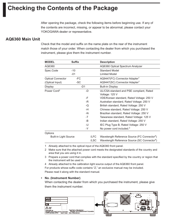
After unboxing, it is necessary to confirm that the host, standard accessories, and optional accessories are complete. The standard accessories are listed in the table below (optional accessories need to be purchased separately):
Category, Part Name, Model/Part Number, Quantity, Key Explanation
Host AQ6360 Host -1 Confirm that the back nameplate model is consistent with the order, and record the instrument number (to be provided when contacting the dealer)
Standard Attachment - Power Supply Cord A1006WD (UL/CSA) 1 needs to be matched with regional standards, such as A1064WD for China and A1009WD for Europe; Suffix - Y without power cord
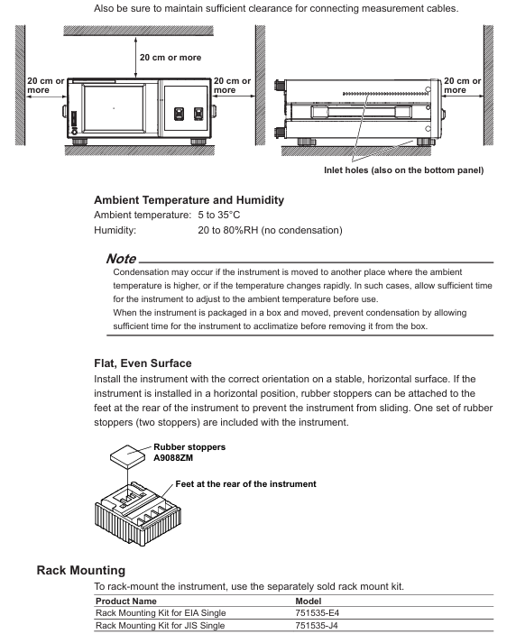
Standard attachment - Other rubber foot pads A9088ZM 2 sheets A9088ZM includes 2 foot pads for fixing instruments to prevent sliding
Standard Attachment - Handbook Beginner's Guide IM AQ6360-02EN 1 Must Read Basic Document
Optional accessories - connector AQ9447 connector adapter (FC) AQ9447-FC - for optical input interface, also available in SC model (AQ9447-SC)
Optional accessories - connector AQ9441 connector adapter (FC) AQ9441-FC - for calibrating light source output interface, also available in SC model (AQ9441-SC)
2. Instrument installation requirements
Installation environment: For indoor use only, avoid direct sunlight, flammable and explosive environments, high vibration/high dust areas
Placement requirements: Horizontal and stable tabletop, anti tilt; Ventilation gap ≥ 200mm (side/back ventilation holes) to prevent internal overheating
Anti impact: Avoid falling (dropping ≥ 2cm may damage the internal monochromator), use original factory grade cushioning packaging during transportation
Rack installation: A separate rack kit (such as EIA standard 751535-E4, JIS standard 751535-J4) needs to be purchased, and the bottom should be supported and not obstruct the ventilation holes during installation
3. Power connection and power on/off
Power specifications: Rated voltage 100-240V AC, frequency 50/60Hz, maximum power consumption ≈ 100VA; allowable voltage range 90-264V AC, frequency 48-63Hz
Power on/off process:
Connect the power cord in the shutdown state (grounded, using a three pin socket);
Turn on the back MAIN POWER switch, and the front POWER light will turn orange;
After waiting for a few seconds, press the front POWER switch, the light turns green, and the instrument starts initialization (displaying STEP 1/9 to STEP 9/9);
To shut down, first press the front POWER switch, confirm the pop-up window, and then click "Yes". After the POWER light turns orange, turn off the MAIN POWER switch.
Basic Operations
1. Control method
Touch screen operation:
Click (select menu/input parameters), drag (move waveform/marker), pinch and zoom (enlarge/shrink waveform);
During waveform operation, a "Operation Tool Window" will pop up, supporting functions such as restoring the initial state and peak alignment.
Mouse/keyboard operation:
Mouse: Left click=Touch screen click, right-click on waveform area to pop up menu, drag to zoom in and out of waveform;
External keyboard: Supports shortcut key operations (such as [SHIFT]+[F1] to start scanning, [ALT]+[F6] to enter system settings). Please refer to the table on page 3-15 of the document for specific mappings.
2. Core operating procedures
Menu operation: Click on the "Three Menu" in the upper right corner of the screen to open the Main Menu window, select a function (such as SWEEP/SETUP/MARKER), switch submenus through "More", and click on the corresponding item to perform the operation.
Parameter input:
Numerical input: Click on the parameter value to pop up the "Parameter Input Window", and adjust it through the numeric keypad or arrow keys (COARSE/FINE switch step size);
String input: When entering a label/file name, a on-screen keyboard pops up, supporting cursor movement and character insertion/deletion.
DUT connection:
Clean the end face of the optical connector (using NTT-AT specialized cleaning agent, press and rotate to wipe);
Connect the optical fiber to the "Optical INPUT" interface of the instrument, and set "NORM" (regular PC) or "ANGLED" (APC) through Main Menu → SETUP → Fiber Connector.
Maintenance and Calibration
1. Firmware update
Update purpose: To enhance the functionality and usability of the instrument, the latest firmware needs to be downloaded from the Yokogawa official website;
Update method:
USB update: Create an "Update" folder in the USB root directory, place the. upd firmware file, and execute it through System → Version → Update (USB);
Network update: Connect to the PC via Ethernet, copy the firmware to the internal Update directory of the instrument, and execute it through Update (NETWORK);
Attention: Do not turn off the power during the update. The instrument will automatically restart after the update, and the settings data will be initialized (backup is required in advance).
2. Accuracy calibration
Wavelength calibration:
Applicable scenario: After 1 hour of preheating and before measurement, ensure wavelength accuracy (±) 0.02nm@1520-1580nm );
Tools: Use built-in reference light sources (/LFC/LSC options) or gas lasers with known wavelength accuracy;
Exception handling: If the error is greater than ± 5nm, contact the dealer for adjustment.
Level calibration:
Tools: 1310/1550nm light source, optical power meter;
Process: Connect the light source to the instrument, measure the peak level, and then connect the light source to the optical power meter to confirm that the difference between the two is within ± 0.5dB (meeting the level accuracy requirements).
3. Daily maintenance and component replacement
Daily cleaning:
External: Wipe with a dry cloth after power failure, and prohibit volatile chemicals;
Optical interface: Clean the connector end face with an alcohol swab and disable compressed air blowing (to prevent dust from entering the monochromator).
Component replacement cycle:
Key Explanation of Component Name Replacement Cycle
LCD backlight ≈ 70000 hours lifespan reference value under normal usage conditions
It is recommended to replace the cooling fan regularly for 3 years to prevent overheating
Backup battery (lithium battery) for 5 years to store settings data, needs to be replaced if expired
Safety and Compliance
1. Safety Warning
Warning (risk of fatal/serious injury):
Cannot directly view the optical output interface (built-in reference light source continuously outputs infrared light, which may cause blindness);
Grounding must be used, and ungrounded extension cords are prohibited;
Do not use in flammable and explosive environments, and do not disassemble the instrument by yourself (there is high pressure inside).
CAUTION (Minor Injury/Equipment Damage Risk):
The instrument is a Class A industrial equipment, which may cause radio interference when used in residential areas and needs to be resolved by the user themselves;
To avoid strong light input (which may damage optical components), initialization must be completed before connecting the DUT.
2. Compliance requirements
Environmental compliance: compliant with the EU WEEE Directive (must not be mixed with household waste for disposal) and the Battery Directive (lithium batteries must be separately recycled);
Laser compliance: The built-in laser light source is Class 1 (compliant with IEC 60825-1:2014, 21 CFR 1040.10/11), with a wavelength of 1.53 μ m and a maximum output power of 0.04mW;
Regional compliance: Taiwan region needs to inquire about restricted substance information for power cord (A1100WD) (official website) https://tmi.yokogawa.com/support/... ).
Key specification parameters
The core specifications of AQ6360 are shown in the following table (limited models should refer to IM AQ6360-51EN):
Specification category specific parameters
Suitable for fiber optic SM (9.5/125 μ m), GI (50/125 μ m, 62.5/125 μ m)
Wavelength range 1200-1650nm
Wavelength accuracy ± 0.02nm (1520-1580nm), ± 0.04nm (1580-1620nm), ± 0.10nm (1200-1650nm)
Wavelength resolution of 0.1/0.2/0.5/1/2nm (setting options), accuracy of ± 5%
Level sensitivity -80dBm (1300-1620nm, resolution 0.1nm, HIGH2 level)
Maximum input power+20dBm (single wavelength resolution input power), maximum safe input power+25dBm (total input power)
Level accuracy ± 0.5dB (1310/1550nm, input -20dBm, MID/HIGH1/HIGH2 levels)
Dynamic range 55dB (peak ± 0.4nm), 40dB (peak ± 0.2nm), resolution 0.1nm
Interface GP-IB, Ethernet, USB (2 each), SVGA output
Display 8.4-inch color LCD (touch screen, resolution 800 × 600 pixels)
Physical dimensions 426 (W) × 177 (H) × 459 (D) mm (excluding protective cover/handle)
Weight ≈ 15.5kg
The working environment temperature is 5-35 ℃, and the humidity is 20-80% RH (without condensation); Performance guarantee temperature 18-28 ℃
- YOKOGAWA
- Reliance
- ADVANCED
- SEW
- ProSoft
- WATLOW
- Kongsberg
- FANUC
- VSD
- DCS
- PLC
- man-machine
- Covid-19
- Energy and Gender
- Energy Access
- Renewable Integration
- Energy Subsidies
- Energy and Water
- Net zero emission
- Energy Security
- Critical Minerals
- A-B
- petroleum
- Mine scale
- Sewage treatment
- cement
- architecture
- Industrial information
- New energy
- Automobile market
- electricity
- Construction site
- HIMA
- ABB
- Rockwell
- Schneider Modicon
- Siemens
- xYCOM
- Yaskawa
- Woodward
- BOSCH Rexroth
- MOOG
- General Electric
- American NI
- Rolls-Royce
- CTI
- Honeywell
- EMERSON
- MAN
- GE
- TRICONEX
- Control Wave
- ALSTOM
- AMAT
- STUDER
- KONGSBERG
- MOTOROLA
- DANAHER MOTION
- Bentley
- Galil
- EATON
- MOLEX
- Triconex
- DEIF
- B&W
- ZYGO
- Aerotech
- DANFOSS
- KOLLMORGEN
- Beijer
- Endress+Hauser
- schneider
- Foxboro
- KB
- REXROTH
- YAMAHA
- Johnson
- Westinghouse
- WAGO
- TOSHIBA
- TEKTRONIX
- BENDER
- BMCM
- SMC
- HITACHI
- HIRSCHMANN
- XP POWER
- Baldor
- Meggitt
- SHINKAWA
- Other Brands
- UniOP
- KUKA
- IBA
- Beckhoff
-
LTI SC52.0040.0012.0000.0 - Servo Drive
-
Lti SC52.0040.0012.0000.0 - Servo Drive
-
Milton Industries LTI Tool By Milton LT1240 - 1/2" Drive Lugnut Remover
-
LTi Drives SO84.200.P030.0000.0-W - Servo Spindle Drive
-
LTI DRIVES LSP08-035-320-30-B0R1PY170 - Servo Motor
-
LTI DRIVES SE84.200.SC00.0001.0-W - Servo Drive
-
Lust CDE34.005.W2.2 - Lti Drives Controller
-
LTi SO84.012.0030.0011.2 - ServoOne Servo Drive
-
LTi Drives SO CM-P.0010.11.00.0 - Servo Drive Controller
-
LTi CDE34.017.W3.0 - Servo Drive
-
LTI Drives CDB32.004, C2.0,SH - Positioning Controller
-
LUST CM-CAN1 - LTi DRIVES Communication Module
-
LTi SO84.012.1030.0000.2 - Servo Drive
-
LTI MOOG CDE54.044 - PITCHMASTER FREQUENCY CONVERTER 181-01019
-
MOOG LTI 181-01019 CDE54.044 - PITCHMASTER FREQUENCY CONVERTER
-
Lust LTi Drives CDE34.010,D2.0 - Servo Drive Controller
-
LTI SO84.032.0003.0101.2 - Servo Drive
-
Seagate 9CC132-302 Harris LTI-CS IRT-34-0021-01 - Hard Drive 160GB
-
LTI SO84.032.0003.0001.2 - Servo Drive
-
LTI SO24.007.0070.0000.1 - SERVO CONTROLLER
-
LTi drive CDA32.003.C3.0.H05-01.PC1 - Servo Drive
-
LTI SO84.016.0030.0000.2 - SERVO CONTROLLER
-
LUST LTI CD A34.008,W1.4, BR - SERVO DRIVE
-
MOOG LTI 181-01019 CDE54.044 - PITCHMASTER FREQUENCY CONVERTER
-
LTI MOOG 181-01019 - PITCH Master Servo Drive CDE54.044
-
LTI SERVO ONE SO84.045.0030.0001.2-W - Drive
-
LUST LTi SO84.032.0040.0000.2 - SERVO ONE DRIVE
-
LTi Drives LSH-074-2-30-3 20/T1,G6.1M - SERVO MOTOR
-
LTI SO84.016.0000.0101.2 - servo drive
-
LTI SA54.0550.0033.0000.0 - Servo Drive
-
LTI SA54.0550.0033.0000.0 - Servo Drive
-
LTI LT 4850 - 3/8" Drive 3-Pc Twist Socket Transmission Drain Plug Removal System
-
LTI Tools LT4400-30 Lock Technology - 3/4" Twist Socket 1/2" Drive Lugnut Remover
-
LTI Tools LT-1400C - 1/2 Drive Wheel Torque Extension Tool
-
LTI Tools LT1250 - 1/2" Drive Dual Sided Socket Lug Nut Remover Tool
-
LTI SO84.032.0003.0101.2 - Servo Drive
-
LTI MOOG 181-01019 - PITCH Master Servo Drive CDE54.044
-
MOOG LTI 181-01019 CDE54.044 - PITCHMASTER FREQUENCY CONVERTER
-
MOOG LTI 181-01019 CDE54.044 - PITCHMASTER FREQUENCY CONVERTER
-
MOOG LTI 181-01019 CDE54.044 - PITCHMASTER FREQUENCY CONVERTER
-
LTI SA54.0550.0033.0000.0 - Servo Drive
-
LTI Tools LT-4800 - 7 Piece Twist Socket 3/8" Drive Oil Drain Plug Removal Set
-
LTI SA54.0550.0033.0000.0 - Servo Drive
-
LTI Drive SO24.007.00300000.0 - Servo Drive
-
LTI TOOLS LTI 1400-I - Drive Wheel Torque Extension
-
LTI Tools LT4400-3 - 3/4" 19mm Twist Socket 1/2" Drive Lugnut
-
LTI TOOLS LTI 1400-BB - Drive Wheel Torque Extension
-
LTI SO84.032.0003.0101.2 - Servo Drive
-
LTI Tools LT-4512 - 3/8" Drive 12mm Twist Socket
-
LTI MOTION Luster SO84.032.0003.0001.2 - Servo Drive
-
LTI Tool By Milton LT1600P - 1" Drive Torx Stick
-
LTI Lust VF1424L,HF,OP2,S56 - Variable Frequency Drive
-
LUST CDA32.004,C1.4,H08,B0 - SERVO DFRIVE CM-CAN1 Module
-
LTI SO84.045.0002.0001.2-W - Drive
-
LTI Lust VF1404M,C9,PT1,BR1 - Inverter Type VF1404M
-
LTI SA54.0550.0033.0000.0 - Servo Drive
-
LTI Tools LT-1400C - 1/2" Drive Wheel Torque Extension
-
Lust LTI DRiVES CDA32.006, C3.0, H09 - Variateur De Fr茅quence Frequency Inverter
-
LTI MOOG CDE54.044 - PITCH master SERVO DRIVE
-
LTI MOOG CDE54.044 - PITCH master SERVO DRIVE
-
LTI SO84.143.0020.0101.2-W - servo drive
-
LTI MOTION SC34.0200.0011.0000.0 - Servo drives
-
LTI SO84.032.0003.0001.2 - Servo Drive
-
LTI DRIVES GmbH MS100 - Assembly Set Mounting Kit
-
LTI SO84.032.0003.0001.2 - Servo Drive
-
LTI SO84.032.0003.0001.2 - Servo Drive
-
LTI MOTION SO84.032.0003.0101.2 - servo drive
-
LTI SO84.032.0003.0101.2 - Servo Drive
-
LTI MOOG CDE54.044 - PITCH master SERVO DRIVE
-
LTI MOTION CDE32.004.C2.4 - Servo drives
-
LTI CDD34.032锛學x.x锛孊R锛孭C1 - Servo Drive
-
Lust LTI DRiVES CDA32.006, C3.0, H09 - Inversor De Frecuencia Frequency Inverter
-
Lust SO84.008.0030.1000.0 - Servo One LTi Drive
-
LTI MOTION SO84.032.0003.0101.2 - Servo drives
-
LUST LTi CDA32.004,C1.4 - SERVO DRIVE
-
LTI MOOG CDE54.044 - PITCH Master SERVO DRIVE
-
LTI KEBA CDB32.004 C2.7, SH - PN: 08673530 Frequency Inverter
-
LTI Tools LT-1400C - 1/2" Drive Wheel Torque Extension
-
LTI LT1400-E - 1/2" Drive Wheel Torque Extension
-
LTI MOOG 181-01019 - PITCH master SERVO DRIVE CDE54.044
-
LTI LSN-097-0510-30-560/T1 - Actuator Motor
-
LTI Tools LT 4800 - 7 Piece 3/8" Drive Twist Socket Oil Drain Plug Removal System
-
LTI DRIVES GmbH MS100 - MONTAGESET Assembly Set Mounting Kit
-
Lti SC52.0040.0012.0000.0 - Servo Drive
-
LTI DRIVES GmbH MS100 - Juego De Montaje Assembly Set Mounting Kit
-
LTi DSM4-14.2-21R83-200 - Drives servomoteur Servo Motor
-
MOOG CDE 54.044.GDA - Pitch Master Industrielle Turbine Lti Drive
-
LTI SO24.004.0030.1000.0 - Servo Drive Controller
-
Lti MOOG CDE54.044 - Pitch Master Servo Drive
-
Lust LTI DRiVES CDA32.006, C3.0, H09 - Inverter
-
LTI MOTION GMBH CDB34.006,W3.0,PC1,H39 - Frequency inverter
-
LTI SO84.032.0003.0001.2 - Servo Drive
-
MOOG CDE 54.044.D - Pitch Master Industrielle Turbine Lti Drive
-
LTI TOOLS LT-1460 - 1/2" DRIVE WHEEL TORQUE EXTENSION KIT 5 PIECE SET
-
Lust Cdb32.003, C2.4 - Lti Drives Servoregulador Frecuencia Servo Controller Inverter
-
Lust LTI DRIVES CDA32.006, C3.0, H09 - Frequency Inverter
-
Lust Lti SO82.004.0030.0000.2 - Servo Drive
-
LTI MOTION SC34.0200.0011.0000.0-SL - Servo drives
-
LTI MOTION SA54.0075.0033.0000.0 - Servo drives
-
LTI MOTION SC32.0075.1011.0000.0 - Servo drives
-
LTI Servo-One Junior SO22.006.0080.1000.0 - Servo Controller Servoregler
-
LUST CDA32.004, C1.4, H08, B0 - Servo Drive & LTI CM-CAN1 Module
-
LTI DRIVES LSP08-035-320-30-B0R1PY170 - Servo Motor
-
LUST LTI CDA32.004,C1.4.H08.B0 - SERVO CONTROLLER DRIVES
-
LUST LTi DRiVES CDS44.072LC1.2 - Servo Drive
-
Lti Servo-One Junior SO22.006.0082.1000.0 - Servo Controller Servoregler
-
LUST CDA32.008,C2.0,HF - Lti DRIVES Spindle Drive Inverter
-
LTI SO22.003.0082.0000.0 - Servo Drives One junior Servo Controller Servoregler
-
Lust Lti Drives CM-CAN1 - Communication Module
-
LUST Lti Drives Vf1202s, G8, I6 - Frequency Inverter Drive
-
LTI DRIVES BR-090.03.540.UR.H38 - Bremswiderstand Brake Resistor
-
LTi DRIVES PM-E40.2DRA054P - Wind Turbine Pitch Control Inverter
-
LTi Drives GmbH br-110.01.540-UR - Brake Resistor
-
LTI Drives LSN-097-0960-30-0560/T1,S4,B - Servo Motor
-
LUST CDA34.006.C2.0 - LTI Drives Servoregler
-
LUST LTI DRIVES SERVO ONE JUNIOR SO24.002.0020.0000.1 - Servo Drive Controller
-
LTI MOTION SO84.032.0003.0001.2 - Servo drives
-
LTI DDTD750V2-120 - IBOP ACTUATOR CYLINDER FOR TOP DRIVE
-
LTI CDE32.004, C2.4 - SERVO DRIVE
-
LUST LTI DRIVES CDD34.017 W3.4PC1 - Servo Drive Controller
-
LTI CDA3208,C3,0,HF - AC SERVO DRIVE
-
LUST LTI DRIVES LSH-074-3-30-560/T1,G6.1S - SERVO MOTOR
-
LUST Lti CDB32.004.C2.4.SH - AC Servo Drive
-
LTi CDA32.006, C3.0, H09 - Servo Drive
-
LTI SO22.003.0010.0000.0 - Servo Drive Servo one junior Servoregler Controller
-
LTi Drives DSM4-14.2-21R83-200 - Servo Motor
-
LUST Lti Drives Lsh-097-1-30-560/T1, 1R - Servomotor
-
LTI 1237 - 7 Piece 1/2" Drive Flip Socket Set

K-JIANG

Add: Jimei North Road, Jimei District, Xiamen, Fujian, China
Tell:+86-15305925923