
K-WANG


Yokogawa AQ6375E Spectral Analyzer Remote Control
Yokogawa AQ6375E Spectral Analyzer Remote Control
Overview
This document is the remote control user manual for Yokogawa AQ6375E spectrometer (2nd edition, released in February 2024), focusing on the GP-IB and Ethernet communication interface functions of the core equipment. It provides detailed guidance for users to complete interface configuration, remote control programming, status monitoring, and automated measurement program writing. At the same time, it provides a complete document system, technical support channels, and version revision records to ensure that users can safely and efficiently achieve spectral measurement tasks through remote control.
Safety regulations and symbol explanations
(1) Warning symbols and their meanings
The manual adopts a three-level warning system and provides French reference to ensure clear safety guidance in multilingual scenarios
Warning: Operations that may cause serious or fatal injuries, such as "operating high-voltage circuits without grounding" and "using equipment in flammable environments", must strictly follow preventive measures.
CAUTION: Indicates operations that may cause minor injury or equipment/data damage, such as "wet hand plugging and unplugging communication cables" or "loose cable connections leading to measurement errors".
Note: Key information indicating the correct operation of the device, such as "Communication interfaces cannot be used simultaneously" and "Command execution sequence requirements".
Equipment symbol: The "manual reference required" symbol marked on the equipment indicates that the operation needs to refer to the manual for special guidance (such as interface parameter configuration).
(2) Core Security Guidelines
Scope of use: Only for spectral measurement (such as wavelength, power, signal-to-noise ratio analysis), strictly prohibited from using beyond the range; Measurement category II in accordance with IEC 61010-031 standard cannot be used for category III/IV scenarios (such as high-voltage grid measurement).
Grounding requirements: The protective grounding terminal of the equipment must be reliably grounded, and the probe grounding wire must be connected to the grounding potential. Double grounding can effectively prevent the risk of electric shock.
Environmental restrictions:
Working environment: temperature 0~50 ℃, humidity 20%~80% RH (non condensing);
Storage environment: temperature -40~71 ℃, humidity 20%~80% RH (non condensing);
It is strictly prohibited to use in damp, dusty, flammable/explosive gas environments. The working altitude should not exceed 2000m, and the storage altitude should not exceed 15000m.
Equipment status: If any signs of damage such as damaged interface cables or exposed metal are found, immediately stop using and contact the dealer for repair; It is strictly prohibited to disassemble or modify communication interface components. Yokogawa shall not be held responsible for any malfunctions caused by unauthorized modifications.
Remote communication interface function and configuration
AQ6375E supports two remote interfaces, GP-IB and Ethernet, which cannot be used simultaneously. When one interface is enabled, the other will be automatically disabled.
(1) GP-IB interface (IEEE 488.2 standard)
1. Core features and parameters
Function: Supports remote reception of device setting instructions, acquisition of measurement data (such as spectral waveforms, analysis results) and status information, compatible with SCPI standard commands and AQ6317 legacy commands.
Technical Specifications:
Interface type: 24 pin GP-IB connector, compliant with IEEE 488-1978 electromechanical specifications;
Communication protocol: Following the IEEE 488.2-1992 functional specification, supporting SH1 (source handshake), AH1 (receive handshake), T6 (talker function), L4 (listener function);
Address range: 0~30 (needs to be set through the device menu and cannot be duplicated with other devices in the bus);
Cable requirements: Use GP-IB cables that comply with IEEE standards, with a single segment length of ≤ 2m and a total length of ≤ 20m.
2. Connection and configuration process
Hardware connection:
Turn off the device and PC power, and connect the GP-IB port of the Rear panel of the device to the GP-IB card of the PC using a GP-IB cable;
Tighten the screws of the cable connector to ensure reliable contact; When connecting multiple devices, use a "daisy chain" or "star" topology and prohibit circular connections.
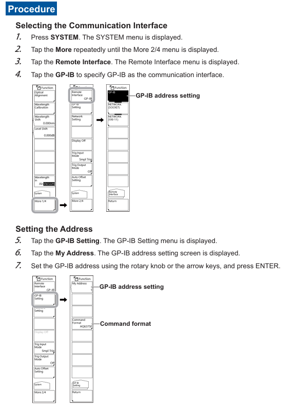
Parameter settings:
Press the SYSTEM button on the device to enter the "More 2/4" menu, select "Remote Interface" → "GP-IB";
Go to "GP-IB Setting" → "My Address", set the address (0-30) using the knob or directional keys, and press ENTER to confirm;
If you need to use AQ6317 compatible commands, go to "Command Format" and select "AQ6317" (default "AQ6375E").
3. Remote/Local Mode Switching
Switch to remote: The PC sends a REN (Remote Enable) signal and sets ATN to "True". The device enters remote mode, and the top of the screen displays "Remote". Only the LOCAL key can be operated (used to release remote).
Switch to local: Press the LOCAL button on the device, or send the GTL (Go To Local) command from the PC; If the PC sends the LLO (Local Lock Out) command, the LOCAL key will be disabled and must be unlocked by setting REN to "False" on the PC.
(2) Ethernet interface (TCP/IP protocol)
1. Core features and parameters
Function: Consistent with GP-IB function, supports remote command reception, data transmission, and status monitoring, and supports Socket and VXI-11 communication modes.
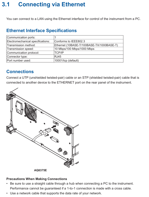
Technical Specifications:
Interface type: 1 RJ45 port, compliant with IEEE 802.3 standard;
Transmission rate: 10/100/1000 Mbps (adaptive);
Port number: default 10001/tcp (Socket mode), VXI-11 mode does not require manual setting;
Compatibility: Supports IPv4/IPv6, only compatible with Windows 8.1/10/11 system PCs (requires installation of Yokogawa USB driver YKMUSB and communication library TMCTL).
2. Connection and configuration process
Hardware connection:
Connect the Ethernet port of the Rear panel to the hub/router (and then connect to the PC) using UTP/STP Ethernet cables;
It is prohibited to use cross cables to directly connect PCs and devices. It is recommended to use a hub connection to ensure stability.
Parameter settings:
Press the SYSTEM key to enter "More 2/4" → "Remote Interface", select "WORK (SOCKET)" or "WORK (VXI-11)";
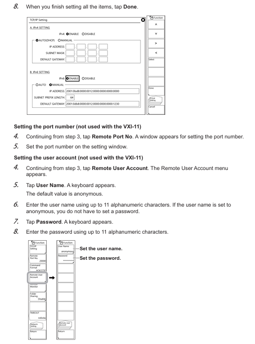
Go to "Network Setting" → "TCP/IP Setting":
IPv4: Select "AUTO (DHCP)" to automatically obtain the address, or manually set the IP address, subnet mask, and default gateway with "MANUAL";
IPv6: Similarly, automatic or manual configuration can be selected;
Socket mode requires additional settings for "Remote Port No." (default 10001) and "Remote User Account" (default username "anonymous", no password required).
3. Remote authentication and connection (Socket mode)
Certification process:
PC sends OPEN "username" command (such as OPEN "anonymous");
The device returns' Authoricate CRAM-MD5 ', and the PC sends the password (anonymous users can ignore it);
The device returns "READY", authentication is successful, and remote mode is activated (the screen displays "Remote").
Disconnect: The PC sends the CLOSE command and the device switches to local mode.
Fundamentals of Programming and Instruction System
(1) Core Programming Concepts
1. Message format
Program message (PC → device): composed of one or more instruction units, separated by semicolons ";", and ending with a termination symbol (LF, ^ END, or LF+^ END); The format is "program header+space+program data", for example: SENSe: WAVelocity: CENTer 1550NM; SPAN 10NM (with a center wavelength of 1550nm and a span of 10nm).
Response message (device → PC): corresponds to the query instruction in the program message, in the format of "response header+space+response data", and ends with LF+^ END; If there are multiple queries, the response will be returned in the order of the queries, for example: * IDN? The response is YOKOGAWA, AQ6375E, 123456789,1.00 (manufacturer, model, serial number, firmware version).
2. Data type
Supporting multiple data formats to adapt to different control requirements, the key types and descriptions are as follows:
Example of Data Type Format Explanation
Decimal numbers (<Decimal>) contain integers (NR1), fixed-point numbers (NR2), and floating-point numbers (NR3). The device receives any format and responds uniformly using NR3 to set the sampling rate: TIMebase: SRATE 1E6
Physical quantities (such as<Voltage>/<Time>) are numerical values prefixed with units or multiples, and units/prefixes are not case sensitive. Time axis setting: TIMebase: TDIV 1US
Register supports decimal, hexadecimal (# H), octal (# Q), and binary (# B), and responds uniformly by setting events in decimal. Enable: STATus: EESE # H01
Pre defined mnemonic for character data (<Character data>), to be selected from options, case insensitive setting coupling method: CHANnel1: COUPling AC
Boolean value (<Boolean>) supports ON/OFF or numerical values (0=OFF, non-zero=ON), and the response is uniformly 0/1 to open the channel display: CHANnel1: DISPlay ON
The string (<String data>) needs to be enclosed in single/double quotation marks, and if it contains quotation marks, two consecutive setting labels need to be entered: CHANnel1: LABel "CH1_TEST"
Block data (<Block data>) is 8-bit binary data in the format of "# N+N bit data length+data byte sequence", only used to respond to waveform data. Response: # 800000010ABCDEFGHIJ
(2) Core Instruction Group
The manual divides instructions into 17 command groups, covering full functions such as device acquisition, analysis, display, and storage. The core command groups and functions are as follows:
Command Group Core Instruction Function Description
ABORt Group: ABORt stops measuring, calibrating, and other ongoing operations (such as scanning initiated by Initiatiate)
CALCulate Group :CALCulate:CATegory、:CALCulate:DATA? Select analysis type (such as spectral width, WDM analysis), query analysis results
SENSe Group: SENSe: WAVelocity: CENTer, SENSe: BANDWidth Set measurement conditions (center wavelength, resolution bandwidth), query measurement parameters
TRACe Group :TRACe:ACTive、:TRACe[:DATA]:Y? Set active trace and query wavelength/level data of trace
MMEMory Group: MMEMory: STORe: TRACe, MMEMory: LOAD: SETTing Store trace data, load device settings files
SYSTem Group :SYSTem:ERRor? 、 SYSTem: COMMunicate: Conform Query Error Queue, Switch Command Format (compatible with AQ6375E/AQ6317)
Common Command Group *IDN? 、 *RST, OPC standard IEEE 488.2 command, query device information, reset device, mark operation completed
Example: Programming process for basic spectral measurement
Initialize device: * RST (reset to default state);
Set measurement conditions: SENSe: WAVelocity: CENTer 1550NM; SPAN 10NM (center wavelength 1550nm, span 10nm), SENSe: BANDWidth 0.1NM (resolution 0.1nm);
Start scan: Initiatate: SMODe SINGle; Initiatate (single scan mode and start);
Query scan status: Status: Operation: EVENT? (Waiting for scanning to complete);
Execution analysis: CALCulate: CATego SWTHresh; CALCulate (THREE method spectral width analysis);
Get result: CALCulate: DATA? (Query and analysis results);
Storage data: MMEMory: STORe: TRACe TRA, CSV, "data1. csv", INT (store trace TRA in CSV format to internal memory).
Status monitoring and troubleshooting
(1) Status reporting mechanism
The device achieves status monitoring through status registers and queues, with core components including:
Status Byte Register (STB): 8-bit binary data that reflects the overall status of the device (e.g. bit7=operation status summary, bit5=standard event summary, bit4=data in output buffer), can be accessed through * STB? Search.
Standard Event Register (ESR): records device standard events (such as operation completion, command errors), which can be enabled through * ESE settings, * ESR? Query and clear.
Operation status register: records the execution status of measurement, calibration, and other operations (such as scanning, calibration completed), through: STATus: OPERation: EVENT? Search.
Error queue: stores the latest error code and description, via SYSTem: ERRor? Query and clear (e.g. error code 300=parameter out of range, 320=undefined variable).
(2) Common problem solving
Troubleshooting steps for problem types and phenomena
Communication connection failure: GP-IB/Ethernet cannot establish connection. 1. Check if the cable connection is secure and confirm that the Ethernet IP address is in the same network segment; 2. GP-IB confirms that the address is not conflicting, and Ethernet confirms that the port number is correct; 3. Restart the device and PC and try again
Instruction execution is unresponsive. After sending the instruction, there is no feedback or error message from the device. 1. Check the syntax of the instruction (such as case and parameter range), refer to Chapter 5 of the manual to confirm the format; 2. Confirm that the device is in remote mode and there is no local lock; 3. Extend the communication timeout (recommended ≥ 30 seconds to avoid automatic offset calibration causing timeout)
1. Confirm that the data format (ASCII/binary) is consistent with the device settings, and that waveform data is missing or has abnormal values due to data transmission distortion; 2. Ethernet checks network bandwidth to avoid transmitting large amounts of data simultaneously; 3. Re execute scanning or calibration to ensure the validity of measurement data
Program Function (Automated Measurement)
(1) Core competencies
Support writing custom programs to achieve full process automation of measurement condition setting, automatic scanning, data analysis, and data storage, without the need for external controller intervention. The program can be stored in the device's internal memory or USB storage medium, supporting 1-100 program numbers.
(2) Program Editing and Execution
Editing process:
Press the APP button, select "Program" ->"Program Edit", and enter the program editing interface;
Select function commands (such as scan settings, analysis start) or special commands (such as loop, delay) through "Command Select", set parameters, and generate program lines;
Supports inserting, copying, and deleting program lines, with a maximum program line count of 200.
Execution process:
Select the target program from the program list and click "Execute" to start it;
During the execution process, real-time output (such as measurement results and status information) can be viewed through the "Output Window", which supports pausing (PAUSE command) or terminating (ABORT command).
(3) Example program: Periodic spectral measurement
plaintext
001 *RST ; Reset device
002 :SENSe:WAVelength:CENTer 1550NM ; Set the center wavelength to 1550nm
003 :SENSe:SPAN 10NM ; Set span to 10nm
004 :SENSe:BANDwidth 0.1NM ; Set resolution to 0.1nm
005 N=5 ; Cycle 5 times
006 :INITiate:SMODe SINGle; :INITiate ; single scan
007 :CALCulate:CATegory SWTHresh ; Choose the THREE method for spectral width analysis
008 :CALCulate ; execution analysis
009 :CALCulate:DATA? ; Query and analyze results
010 :MMEMory:STORe:DATA "result.csv",INT ; Store results in internal memory
011 WAIT 10S ; Delay for 10 seconds
012 N=N-1; IF N<>0 GOTO 006 ; Loop until N=0
013 END ; Program ends
- YOKOGAWA
- Reliance
- ADVANCED
- SEW
- ProSoft
- WATLOW
- Kongsberg
- FANUC
- VSD
- DCS
- PLC
- man-machine
- Covid-19
- Energy and Gender
- Energy Access
- Renewable Integration
- Energy Subsidies
- Energy and Water
- Net zero emission
- Energy Security
- Critical Minerals
- A-B
- petroleum
- Mine scale
- Sewage treatment
- cement
- architecture
- Industrial information
- New energy
- Automobile market
- electricity
- Construction site
- HIMA
- ABB
- Rockwell
- Schneider Modicon
- Siemens
- xYCOM
- Yaskawa
- Woodward
- BOSCH Rexroth
- MOOG
- General Electric
- American NI
- Rolls-Royce
- CTI
- Honeywell
- EMERSON
- MAN
- GE
- TRICONEX
- Control Wave
- ALSTOM
- AMAT
- STUDER
- KONGSBERG
- MOTOROLA
- DANAHER MOTION
- Bentley
- Galil
- EATON
- MOLEX
- Triconex
- DEIF
- B&W
- ZYGO
- Aerotech
- DANFOSS
- KOLLMORGEN
- Beijer
- Endress+Hauser
- schneider
- Foxboro
- KB
- REXROTH
- YAMAHA
- Johnson
- Westinghouse
- WAGO
- TOSHIBA
- TEKTRONIX
- BENDER
- BMCM
- SMC
- HITACHI
- HIRSCHMANN
- XP POWER
- Baldor
- Meggitt
- SHINKAWA
- Other Brands
- UniOP
- KUKA
- IBA
- Beckhoff
-
LTI SC52.0040.0012.0000.0 - Servo Drive
-
Lti SC52.0040.0012.0000.0 - Servo Drive
-
Milton Industries LTI Tool By Milton LT1240 - 1/2" Drive Lugnut Remover
-
LTi Drives SO84.200.P030.0000.0-W - Servo Spindle Drive
-
LTI DRIVES LSP08-035-320-30-B0R1PY170 - Servo Motor
-
LTI DRIVES SE84.200.SC00.0001.0-W - Servo Drive
-
Lust CDE34.005.W2.2 - Lti Drives Controller
-
LTi SO84.012.0030.0011.2 - ServoOne Servo Drive
-
LTi Drives SO CM-P.0010.11.00.0 - Servo Drive Controller
-
LTi CDE34.017.W3.0 - Servo Drive
-
LTI Drives CDB32.004, C2.0,SH - Positioning Controller
-
LUST CM-CAN1 - LTi DRIVES Communication Module
-
LTi SO84.012.1030.0000.2 - Servo Drive
-
LTI MOOG CDE54.044 - PITCHMASTER FREQUENCY CONVERTER 181-01019
-
MOOG LTI 181-01019 CDE54.044 - PITCHMASTER FREQUENCY CONVERTER
-
Lust LTi Drives CDE34.010,D2.0 - Servo Drive Controller
-
LTI SO84.032.0003.0101.2 - Servo Drive
-
Seagate 9CC132-302 Harris LTI-CS IRT-34-0021-01 - Hard Drive 160GB
-
LTI SO84.032.0003.0001.2 - Servo Drive
-
LTI SO24.007.0070.0000.1 - SERVO CONTROLLER
-
LTi drive CDA32.003.C3.0.H05-01.PC1 - Servo Drive
-
LTI SO84.016.0030.0000.2 - SERVO CONTROLLER
-
LUST LTI CD A34.008,W1.4, BR - SERVO DRIVE
-
MOOG LTI 181-01019 CDE54.044 - PITCHMASTER FREQUENCY CONVERTER
-
LTI MOOG 181-01019 - PITCH Master Servo Drive CDE54.044
-
LTI SERVO ONE SO84.045.0030.0001.2-W - Drive
-
LUST LTi SO84.032.0040.0000.2 - SERVO ONE DRIVE
-
LTi Drives LSH-074-2-30-3 20/T1,G6.1M - SERVO MOTOR
-
LTI SO84.016.0000.0101.2 - servo drive
-
LTI SA54.0550.0033.0000.0 - Servo Drive
-
LTI SA54.0550.0033.0000.0 - Servo Drive
-
LTI LT 4850 - 3/8" Drive 3-Pc Twist Socket Transmission Drain Plug Removal System
-
LTI Tools LT4400-30 Lock Technology - 3/4" Twist Socket 1/2" Drive Lugnut Remover
-
LTI Tools LT-1400C - 1/2 Drive Wheel Torque Extension Tool
-
LTI Tools LT1250 - 1/2" Drive Dual Sided Socket Lug Nut Remover Tool
-
LTI SO84.032.0003.0101.2 - Servo Drive
-
LTI MOOG 181-01019 - PITCH Master Servo Drive CDE54.044
-
MOOG LTI 181-01019 CDE54.044 - PITCHMASTER FREQUENCY CONVERTER
-
MOOG LTI 181-01019 CDE54.044 - PITCHMASTER FREQUENCY CONVERTER
-
MOOG LTI 181-01019 CDE54.044 - PITCHMASTER FREQUENCY CONVERTER
-
LTI SA54.0550.0033.0000.0 - Servo Drive
-
LTI Tools LT-4800 - 7 Piece Twist Socket 3/8" Drive Oil Drain Plug Removal Set
-
LTI SA54.0550.0033.0000.0 - Servo Drive
-
LTI Drive SO24.007.00300000.0 - Servo Drive
-
LTI TOOLS LTI 1400-I - Drive Wheel Torque Extension
-
LTI Tools LT4400-3 - 3/4" 19mm Twist Socket 1/2" Drive Lugnut
-
LTI TOOLS LTI 1400-BB - Drive Wheel Torque Extension
-
LTI SO84.032.0003.0101.2 - Servo Drive
-
LTI Tools LT-4512 - 3/8" Drive 12mm Twist Socket
-
LTI MOTION Luster SO84.032.0003.0001.2 - Servo Drive
-
LTI Tool By Milton LT1600P - 1" Drive Torx Stick
-
LTI Lust VF1424L,HF,OP2,S56 - Variable Frequency Drive
-
LUST CDA32.004,C1.4,H08,B0 - SERVO DFRIVE CM-CAN1 Module
-
LTI SO84.045.0002.0001.2-W - Drive
-
LTI Lust VF1404M,C9,PT1,BR1 - Inverter Type VF1404M
-
LTI SA54.0550.0033.0000.0 - Servo Drive
-
LTI Tools LT-1400C - 1/2" Drive Wheel Torque Extension
-
Lust LTI DRiVES CDA32.006, C3.0, H09 - Variateur De Fr茅quence Frequency Inverter
-
LTI MOOG CDE54.044 - PITCH master SERVO DRIVE
-
LTI MOOG CDE54.044 - PITCH master SERVO DRIVE
-
LTI SO84.143.0020.0101.2-W - servo drive
-
LTI MOTION SC34.0200.0011.0000.0 - Servo drives
-
LTI SO84.032.0003.0001.2 - Servo Drive
-
LTI DRIVES GmbH MS100 - Assembly Set Mounting Kit
-
LTI SO84.032.0003.0001.2 - Servo Drive
-
LTI SO84.032.0003.0001.2 - Servo Drive
-
LTI MOTION SO84.032.0003.0101.2 - servo drive
-
LTI SO84.032.0003.0101.2 - Servo Drive
-
LTI MOOG CDE54.044 - PITCH master SERVO DRIVE
-
LTI MOTION CDE32.004.C2.4 - Servo drives
-
LTI CDD34.032锛學x.x锛孊R锛孭C1 - Servo Drive
-
Lust LTI DRiVES CDA32.006, C3.0, H09 - Inversor De Frecuencia Frequency Inverter
-
Lust SO84.008.0030.1000.0 - Servo One LTi Drive
-
LTI MOTION SO84.032.0003.0101.2 - Servo drives
-
LUST LTi CDA32.004,C1.4 - SERVO DRIVE
-
LTI MOOG CDE54.044 - PITCH Master SERVO DRIVE
-
LTI KEBA CDB32.004 C2.7, SH - PN: 08673530 Frequency Inverter
-
LTI Tools LT-1400C - 1/2" Drive Wheel Torque Extension
-
LTI LT1400-E - 1/2" Drive Wheel Torque Extension
-
LTI MOOG 181-01019 - PITCH master SERVO DRIVE CDE54.044
-
LTI LSN-097-0510-30-560/T1 - Actuator Motor
-
LTI Tools LT 4800 - 7 Piece 3/8" Drive Twist Socket Oil Drain Plug Removal System
-
LTI DRIVES GmbH MS100 - MONTAGESET Assembly Set Mounting Kit
-
Lti SC52.0040.0012.0000.0 - Servo Drive
-
LTI DRIVES GmbH MS100 - Juego De Montaje Assembly Set Mounting Kit
-
LTi DSM4-14.2-21R83-200 - Drives servomoteur Servo Motor
-
MOOG CDE 54.044.GDA - Pitch Master Industrielle Turbine Lti Drive
-
LTI SO24.004.0030.1000.0 - Servo Drive Controller
-
Lti MOOG CDE54.044 - Pitch Master Servo Drive
-
Lust LTI DRiVES CDA32.006, C3.0, H09 - Inverter
-
LTI MOTION GMBH CDB34.006,W3.0,PC1,H39 - Frequency inverter
-
LTI SO84.032.0003.0001.2 - Servo Drive
-
MOOG CDE 54.044.D - Pitch Master Industrielle Turbine Lti Drive
-
LTI TOOLS LT-1460 - 1/2" DRIVE WHEEL TORQUE EXTENSION KIT 5 PIECE SET
-
Lust Cdb32.003, C2.4 - Lti Drives Servoregulador Frecuencia Servo Controller Inverter
-
Lust LTI DRIVES CDA32.006, C3.0, H09 - Frequency Inverter
-
Lust Lti SO82.004.0030.0000.2 - Servo Drive
-
LTI MOTION SC34.0200.0011.0000.0-SL - Servo drives
-
LTI MOTION SA54.0075.0033.0000.0 - Servo drives
-
LTI MOTION SC32.0075.1011.0000.0 - Servo drives
-
LTI Servo-One Junior SO22.006.0080.1000.0 - Servo Controller Servoregler
-
LUST CDA32.004, C1.4, H08, B0 - Servo Drive & LTI CM-CAN1 Module
-
LTI DRIVES LSP08-035-320-30-B0R1PY170 - Servo Motor
-
LUST LTI CDA32.004,C1.4.H08.B0 - SERVO CONTROLLER DRIVES
-
LUST LTi DRiVES CDS44.072LC1.2 - Servo Drive
-
Lti Servo-One Junior SO22.006.0082.1000.0 - Servo Controller Servoregler
-
LUST CDA32.008,C2.0,HF - Lti DRIVES Spindle Drive Inverter
-
LTI SO22.003.0082.0000.0 - Servo Drives One junior Servo Controller Servoregler
-
Lust Lti Drives CM-CAN1 - Communication Module
-
LUST Lti Drives Vf1202s, G8, I6 - Frequency Inverter Drive
-
LTI DRIVES BR-090.03.540.UR.H38 - Bremswiderstand Brake Resistor
-
LTi DRIVES PM-E40.2DRA054P - Wind Turbine Pitch Control Inverter
-
LTi Drives GmbH br-110.01.540-UR - Brake Resistor
-
LTI Drives LSN-097-0960-30-0560/T1,S4,B - Servo Motor
-
LUST CDA34.006.C2.0 - LTI Drives Servoregler
-
LUST LTI DRIVES SERVO ONE JUNIOR SO24.002.0020.0000.1 - Servo Drive Controller
-
LTI MOTION SO84.032.0003.0001.2 - Servo drives
-
LTI DDTD750V2-120 - IBOP ACTUATOR CYLINDER FOR TOP DRIVE
-
LTI CDE32.004, C2.4 - SERVO DRIVE
-
LUST LTI DRIVES CDD34.017 W3.4PC1 - Servo Drive Controller
-
LTI CDA3208,C3,0,HF - AC SERVO DRIVE
-
LUST LTI DRIVES LSH-074-3-30-560/T1,G6.1S - SERVO MOTOR
-
LUST Lti CDB32.004.C2.4.SH - AC Servo Drive
-
LTi CDA32.006, C3.0, H09 - Servo Drive
-
LTI SO22.003.0010.0000.0 - Servo Drive Servo one junior Servoregler Controller
-
LTi Drives DSM4-14.2-21R83-200 - Servo Motor
-
LUST Lti Drives Lsh-097-1-30-560/T1, 1R - Servomotor
-
LTI 1237 - 7 Piece 1/2" Drive Flip Socket Set

K-JIANG

Add: Jimei North Road, Jimei District, Xiamen, Fujian, China
Tell:+86-15305925923