
K-WANG


YOKOGAWA AQ7420 High-Resolution Reflectometer
YOKOGAWA AQ7420 High-Resolution Reflectometer
Instrument positioning and core applications
AQ7420 is a high-resolution reflectometer based on the principle of Time Domain Optical Coherence Tomography (TD-OCT) with built-in Michelson interferometer. Its core function is to measure three key parameters of optical devices through USB connection with the control PC
Optical Return Loss (RL): measures the return loss of fiber optic connectors, internal scratches, and device connection points, locates the position (with a maximum accuracy of 1 μ m) and intensity of reflection points.
Burnout Detection: Scan the distribution of return loss throughout the entire measurement range to identify abnormal reflection peaks such as fiber breakage and component defects.
Optical Insertion Loss (IL): measures the power attenuation of an optical signal passing through a Device Under Test (DUT) to evaluate the transmission performance of the device.
The instrument needs to be used in conjunction with a dedicated PC application, supporting local operation and TCP/IP remote control. The measurement results can be automatically graded, saved, and printed to meet the requirements of automated testing.
PC application installation and environmental requirements
1. Hardware and system requirements
Before installation, it is necessary to confirm that the control PC meets the following conditions, otherwise it may cause abnormal software operation or communication failure:
Project Requirements Explanation
The operating systems Windows 10 (32/64 bit) and Windows 11 do not support Windows XP/Vista/7/8 and tablet mode
Hardware configuration with at least 10MB of free hard disk space, USB interface free space for software installation and data storage, USB for instrument communication
Display resolution of 1024 × 768 pixels and above, 256 colors and above to ensure complete display of the operation interface, clear waveform diagram
The driver relies on NI-VISA 16.0 and above versions for communication between instruments and PCs, requiring VISA drivers. If not installed, it needs to be installed from the product CD first
2. Installation and uninstallation process
(1) Software installation steps
Preparation: Close the installed AQ7420 series software (if any) and log in to Windows with administrator privileges.
Start installation: Insert the product CD and run the path in English Application ARB-EDIT Setup. EXE (or enter the path through "Start Menu ->Run").
Driver installation: After completing the PC application installation as prompted, the FTDI CDM driver installation window will automatically pop up. Click "Extract → Next → I agree → Finish" in sequence to complete the driver deployment.
Start verification: After installation is complete, add the "AQ7420Series-OLCR" program under "Start Menu → YOKOGAWA", generate a shortcut icon on the desktop, double-click to start and enter the main interface.
(2) Uninstalling process (taking Windows 11 as an example)
Open "Control Panel ->Apps ->Installed Apps" and find "AQ7420Series'OLCR".
Click on the icon on the right side of the program, select "Uninstall", confirm and complete the uninstallation; If there are any remaining installation folders, they can be manually deleted (self built data needs to be backed up in advance).
(3) Connection exception handling
If the software prompts "Device Error" when starting, check:
Is the USB cable securely connected to the AQ7420 and PC.
Whether the VISA driver is installed properly (can be verified through NI MAX tool).
Whether the instrument power is turned on and whether the warm up is completed (it is recommended to perform reference measurements after preheating for 1 hour).
If you only want to view data without connecting the instrument, you can click "Viewer Mode" to enter the view mode.
Core functions and operating procedures
1. Preparation before measurement
(1) Instrument preheating and reference measurement
Preheating requirement: After starting up, the "Repeat Mode" should be turned on to run for 1 hour for preheating, to avoid temperature drift affecting measurement accuracy; After preheating, the reference measurement calibration system needs to be executed.
Reference measurement type:
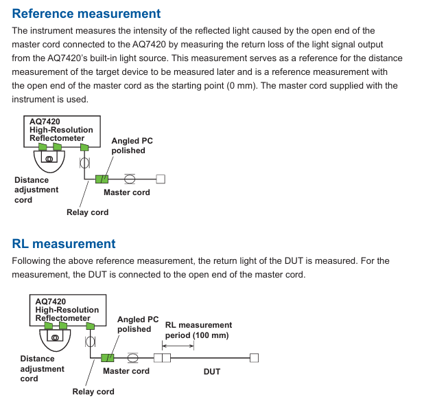
Detection REF: The reference measurement for RL and burn detection requires the use of a dedicated main cable (Master Cord), with the open end of the main cable as the measurement starting point (0mm), to record the reference reflection intensity.
IL REF: Reference measurement of insertion loss, connect the main cable directly to the optical input port of AQ740023 sensor head, and record the reference optical power.
All REF: Simultaneously execute Detection REF and IL REF, suitable for scenarios where RL/burn detection and IL need to be measured simultaneously.
(2) Key hardware connections
When measuring different parameters, cables need to be connected according to specifications. The core components include the main cable (standard accessories, can be purchased separately), distance adjustment cable, relay cable, FC/APC adapter, and AQ740023 sensor head. The example connections are as follows:
RL/burn detection: AQ7420 test port → relay cable → FC/APC adapter → main cable → device under test (DUT), the open end of the main cable should be kept away from reflective objects (at least 100mm).
IL measurement: AQ7420 test port → relay cable → FC/APC adapter → main cable → DUT → AQ740023 sensor head, ensure that the connector end face is clean (dirt can cause excessive splicing loss, prompt "Under Range").
2. Measurement setup (Setup window)
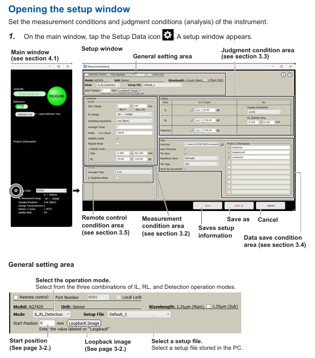
Open the settings window through the "Setup" button on the main interface, configure measurement conditions, grading standards, data saving, and remote control parameters. The core settings are as follows:
(1) General settings
Operation mode: Supports three combination modes - "IL, RL, Detection" (single measurement of three types of parameters), "Detection" (only RL and burn detection), and "IL" (only IL).
Wavelength selection: main wavelength of 1.31 μ m, sub wavelength of 1.55 μ m (dual wavelength data can be measured simultaneously when sub wavelength needs to be enabled).
Start Position: Used for long-distance cable adjustment (optional accessory), input the distance compensation value displayed in the "Loopback Image" window to correct the measurement starting point offset.
(2) Measurement conditions
Scope of Settings/Option Description
Measurement distance (Span) from 0 to 100mm. The measurement time increases with distance and defaults to 100mm
RL measurement range -14.7~-85dB/-50~-100dB. The former is suitable for strong reflection scenarios, while the latter is suitable for weak reflection (such as deep loss)
The higher the sampling resolution of High (1 μ m)/Middle (4 μ m)/Low (8 μ m), the higher the measurement accuracy but the longer the time consumption
The average number of detections (Detection) is 1-16 times, and the more detections, the lower the noise
The refractive index (Index) of 1.0000~2.0000 is set according to the refractive index of the measured fiber (such as SM fiber 1.4674), which affects the accuracy of distance measurement
After turning on/off the Stability Mode, it automatically corrects the length drift of the main cable caused by changes in ambient temperature (0mm correction)
(3) Grading criteria (Analysis)
Set the qualified threshold for each parameter, and automatically compare and grade after measurement (blue "Pass", red "Fail"):
IL threshold: 0~40dB, supports setting display resolution (1/10~1/10000).
RL threshold: -120~-10dB, can limit the grading range (-10~110mm).
Burn detection threshold: -120~-10dB. Reflection peaks exceeding the threshold will be marked and counted on the waveform.
(4) Data saving settings
Storage path: Specify the data storage directory, enable "Auto Directory" to automatically create subfolders by "year/month/day".
File type: Waveform data supports CSV (numerical), JPG/BMP (image), measurement data (PS format) includes grading results, peak positions, and RL values, and dual wavelength data is merged and saved.
Auto Save: After enabling "File Save", save numerical data on a daily basis; The 'Waveform Save' supports modes such as' NG only auto save 'and' fully auto save 'to meet different testing needs.
3. Measurement operation process
(1) Reference measurement (taking PC polished DUT as an example)
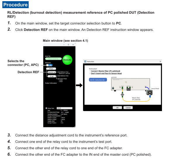
RL/Burn Detection Reference (Detection REF):
Set the "Target Connector Selection" on the main interface to "PC", click on "Detection REF", and follow the prompts to connect the distance adjustment cable, relay cable, FC adapter, and PC polishing main cable (open end).
Click "OK" to perform the reference measurement. After completion, the command window will automatically close and record the reference reflection value at the 0mm starting point.
IL Reference (IL REF):
Click on "IL REF" on the main interface and connect the open end of the main cable to the optical input port of the AQ740023 sensor head.
Click "OK" to perform reference measurement, record the reference optical power, and use it for subsequent IL calculation (power difference after DUT insertion).
(2) DUT measurement
RL/Burn Detection Measurement:
Disconnect the main cable from the open end, connect the DUT (ensure the connector is clean and scratch free), and enter the DUT serial number (optional, supports automatic increment).
Click the "MEASURE" button on the main interface, and the instrument will scan the distribution of return loss within the measurement range. After completion, the RL value will be output in the "Measurement Result Display Area", and the waveform will display the burn detection peak.
IL measurement:
Connect the DUT in series between the main cable and AQ740023, click "Measure", and the instrument calculates the insertion loss of the DUT (the difference between the reference power and the measured power), and the result is displayed in real time (enabling "IL Realtime Mode" for continuous measurement).
4. Data analysis (Analysis window)
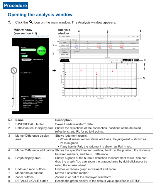
After the measurement is completed, click the "Analysis Mode" button on the main interface to enter the analysis window, which supports waveform detail viewing and marking analysis:
Waveform interaction: Drag and drop the mouse to pan the waveform, right-click or scroll to zoom in and out of a specific area, and use "DEFILT SCALE" to restore the default display scale.
Marking operation:
Click the "Marker Add" button to add markers on the waveform, and check the distance (mm) and RL value (dB) of the marker position.
Support calculating the distance difference and RL difference between two markers (such as A-B distance difference and RL difference) to assist in locating defect spacing.
Peak recognition: Reflection peaks that exceed the classification threshold are automatically marked, and the table displays the peak position, RL value, and classification result, making it easy to quickly locate outliers.
5. Data storage and printing
(1) Data saving
Manual Save: Click "SAVE" in the analysis window, and save the waveform data (CSV/JPG/BMP) according to the set path. The file name should include the date, time, and serial number (such as "PW20241115_103040-AA1. csv").
Auto Save: After enabling "Waveform Save", the measurement is automatically saved upon completion (only data classified as Fail is saved in NG mode to save storage space).
(2) Report printing
Click the "Report" button on the main interface to open the Windows print settings window, select the printer or "PDF" (generate PDF file).
The printed content includes instrument model, measurement time, set parameters, IL/RL/Detection results, waveform diagrams, and peak data, which are automatically summarized into a single page report for easy testing and archiving.
Remote control
1. Preparation for remote control
Hardware connection: The control PC is connected to the remote server via LAN, and the instrument is connected to the control PC via USB, ensuring that the network port (default 8889) is not blocked by a firewall.
Software settings: Enable "Remote Setting" in the PC application "Setup window → Remote Conditions", set the port number (consistent with the remote terminal), and enable "Local Key Display" to display the "Local Release Button" when connecting remotely.
2. Login and permission management
Login command: Remote terminal sends LOGIN<wsp>ID, Password. The default administrator ID/password is "reflectometer/reflectometer". After successful login, control the PC to display the "Remote" icon.
Permission classification:
Administrator: Can modify ID/password (IDWrite: ADMin<wsp>new ID, new password), create users (up to 5).
User: Only performs basic operations such as measurement and query results, and does not have permission to modify system settings.
Logout command: Send: LOGOut to disconnect the remote connection, or click on the control PC "Local Key" to force a switch to local control.
3. Core control commands
Remote control is based on TCP/IP protocol, with commands divided into "program messages" (control) and "query messages" (read). Examples of key commands are as follows:
Command group command example function
MAIN group: MAIN: EASure start/stop measurement
: MAIN: REF: ILREf Perform IL reference measurement
:MAIN:RESUlt:JUDGe? Query the overall judgment level result (0=Fail, 1=Pass)
SETUp group: SETUp: MODE<wsp>0 Set the operation mode to "IL, RL, Detection"
SETUP: EASure: STARt<wsp>20 Set measurement starting position 20mm
General command * IDN? Query instrument information (manufacturer, model, serial number, firmware version)
*RST resets instrument settings and stops all processes
The command supports abbreviations (such as SETUp, which can be abbreviated as SETU), is not case sensitive, the response message is in ASCII format, and the error command returns "Invalid Command".
- YOKOGAWA
- Reliance
- ADVANCED
- SEW
- ProSoft
- WATLOW
- Kongsberg
- FANUC
- VSD
- DCS
- PLC
- man-machine
- Covid-19
- Energy and Gender
- Energy Access
- Renewable Integration
- Energy Subsidies
- Energy and Water
- Net zero emission
- Energy Security
- Critical Minerals
- A-B
- petroleum
- Mine scale
- Sewage treatment
- cement
- architecture
- Industrial information
- New energy
- Automobile market
- electricity
- Construction site
- HIMA
- ABB
- Rockwell
- Schneider Modicon
- Siemens
- xYCOM
- Yaskawa
- Woodward
- BOSCH Rexroth
- MOOG
- General Electric
- American NI
- Rolls-Royce
- CTI
- Honeywell
- EMERSON
- MAN
- GE
- TRICONEX
- Control Wave
- ALSTOM
- AMAT
- STUDER
- KONGSBERG
- MOTOROLA
- DANAHER MOTION
- Bentley
- Galil
- EATON
- MOLEX
- Triconex
- DEIF
- B&W
- ZYGO
- Aerotech
- DANFOSS
- KOLLMORGEN
- Beijer
- Endress+Hauser
- schneider
- Foxboro
- KB
- REXROTH
- YAMAHA
- Johnson
- Westinghouse
- WAGO
- TOSHIBA
- TEKTRONIX
- BENDER
- BMCM
- SMC
- HITACHI
- HIRSCHMANN
- XP POWER
- Baldor
- Meggitt
- SHINKAWA
- Other Brands
- UniOP
- KUKA
- IBA
- Beckhoff
-
LTI SC52.0040.0012.0000.0 - Servo Drive
-
Lti SC52.0040.0012.0000.0 - Servo Drive
-
Milton Industries LTI Tool By Milton LT1240 - 1/2" Drive Lugnut Remover
-
LTi Drives SO84.200.P030.0000.0-W - Servo Spindle Drive
-
LTI DRIVES LSP08-035-320-30-B0R1PY170 - Servo Motor
-
LTI DRIVES SE84.200.SC00.0001.0-W - Servo Drive
-
Lust CDE34.005.W2.2 - Lti Drives Controller
-
LTi SO84.012.0030.0011.2 - ServoOne Servo Drive
-
LTi Drives SO CM-P.0010.11.00.0 - Servo Drive Controller
-
LTi CDE34.017.W3.0 - Servo Drive
-
LTI Drives CDB32.004, C2.0,SH - Positioning Controller
-
LUST CM-CAN1 - LTi DRIVES Communication Module
-
LTi SO84.012.1030.0000.2 - Servo Drive
-
LTI MOOG CDE54.044 - PITCHMASTER FREQUENCY CONVERTER 181-01019
-
MOOG LTI 181-01019 CDE54.044 - PITCHMASTER FREQUENCY CONVERTER
-
Lust LTi Drives CDE34.010,D2.0 - Servo Drive Controller
-
LTI SO84.032.0003.0101.2 - Servo Drive
-
Seagate 9CC132-302 Harris LTI-CS IRT-34-0021-01 - Hard Drive 160GB
-
LTI SO84.032.0003.0001.2 - Servo Drive
-
LTI SO24.007.0070.0000.1 - SERVO CONTROLLER
-
LTi drive CDA32.003.C3.0.H05-01.PC1 - Servo Drive
-
LTI SO84.016.0030.0000.2 - SERVO CONTROLLER
-
LUST LTI CD A34.008,W1.4, BR - SERVO DRIVE
-
MOOG LTI 181-01019 CDE54.044 - PITCHMASTER FREQUENCY CONVERTER
-
LTI MOOG 181-01019 - PITCH Master Servo Drive CDE54.044
-
LTI SERVO ONE SO84.045.0030.0001.2-W - Drive
-
LUST LTi SO84.032.0040.0000.2 - SERVO ONE DRIVE
-
LTi Drives LSH-074-2-30-3 20/T1,G6.1M - SERVO MOTOR
-
LTI SO84.016.0000.0101.2 - servo drive
-
LTI SA54.0550.0033.0000.0 - Servo Drive
-
LTI SA54.0550.0033.0000.0 - Servo Drive
-
LTI LT 4850 - 3/8" Drive 3-Pc Twist Socket Transmission Drain Plug Removal System
-
LTI Tools LT4400-30 Lock Technology - 3/4" Twist Socket 1/2" Drive Lugnut Remover
-
LTI Tools LT-1400C - 1/2 Drive Wheel Torque Extension Tool
-
LTI Tools LT1250 - 1/2" Drive Dual Sided Socket Lug Nut Remover Tool
-
LTI SO84.032.0003.0101.2 - Servo Drive
-
LTI MOOG 181-01019 - PITCH Master Servo Drive CDE54.044
-
MOOG LTI 181-01019 CDE54.044 - PITCHMASTER FREQUENCY CONVERTER
-
MOOG LTI 181-01019 CDE54.044 - PITCHMASTER FREQUENCY CONVERTER
-
MOOG LTI 181-01019 CDE54.044 - PITCHMASTER FREQUENCY CONVERTER
-
LTI SA54.0550.0033.0000.0 - Servo Drive
-
LTI Tools LT-4800 - 7 Piece Twist Socket 3/8" Drive Oil Drain Plug Removal Set
-
LTI SA54.0550.0033.0000.0 - Servo Drive
-
LTI Drive SO24.007.00300000.0 - Servo Drive
-
LTI TOOLS LTI 1400-I - Drive Wheel Torque Extension
-
LTI Tools LT4400-3 - 3/4" 19mm Twist Socket 1/2" Drive Lugnut
-
LTI TOOLS LTI 1400-BB - Drive Wheel Torque Extension
-
LTI SO84.032.0003.0101.2 - Servo Drive
-
LTI Tools LT-4512 - 3/8" Drive 12mm Twist Socket
-
LTI MOTION Luster SO84.032.0003.0001.2 - Servo Drive
-
LTI Tool By Milton LT1600P - 1" Drive Torx Stick
-
LTI Lust VF1424L,HF,OP2,S56 - Variable Frequency Drive
-
LUST CDA32.004,C1.4,H08,B0 - SERVO DFRIVE CM-CAN1 Module
-
LTI SO84.045.0002.0001.2-W - Drive
-
LTI Lust VF1404M,C9,PT1,BR1 - Inverter Type VF1404M
-
LTI SA54.0550.0033.0000.0 - Servo Drive
-
LTI Tools LT-1400C - 1/2" Drive Wheel Torque Extension
-
Lust LTI DRiVES CDA32.006, C3.0, H09 - Variateur De Fr茅quence Frequency Inverter
-
LTI MOOG CDE54.044 - PITCH master SERVO DRIVE
-
LTI MOOG CDE54.044 - PITCH master SERVO DRIVE
-
LTI SO84.143.0020.0101.2-W - servo drive
-
LTI MOTION SC34.0200.0011.0000.0 - Servo drives
-
LTI SO84.032.0003.0001.2 - Servo Drive
-
LTI DRIVES GmbH MS100 - Assembly Set Mounting Kit
-
LTI SO84.032.0003.0001.2 - Servo Drive
-
LTI SO84.032.0003.0001.2 - Servo Drive
-
LTI MOTION SO84.032.0003.0101.2 - servo drive
-
LTI SO84.032.0003.0101.2 - Servo Drive
-
LTI MOOG CDE54.044 - PITCH master SERVO DRIVE
-
LTI MOTION CDE32.004.C2.4 - Servo drives
-
LTI CDD34.032锛學x.x锛孊R锛孭C1 - Servo Drive
-
Lust LTI DRiVES CDA32.006, C3.0, H09 - Inversor De Frecuencia Frequency Inverter
-
Lust SO84.008.0030.1000.0 - Servo One LTi Drive
-
LTI MOTION SO84.032.0003.0101.2 - Servo drives
-
LUST LTi CDA32.004,C1.4 - SERVO DRIVE
-
LTI MOOG CDE54.044 - PITCH Master SERVO DRIVE
-
LTI KEBA CDB32.004 C2.7, SH - PN: 08673530 Frequency Inverter
-
LTI Tools LT-1400C - 1/2" Drive Wheel Torque Extension
-
LTI LT1400-E - 1/2" Drive Wheel Torque Extension
-
LTI MOOG 181-01019 - PITCH master SERVO DRIVE CDE54.044
-
LTI LSN-097-0510-30-560/T1 - Actuator Motor
-
LTI Tools LT 4800 - 7 Piece 3/8" Drive Twist Socket Oil Drain Plug Removal System
-
LTI DRIVES GmbH MS100 - MONTAGESET Assembly Set Mounting Kit
-
Lti SC52.0040.0012.0000.0 - Servo Drive
-
LTI DRIVES GmbH MS100 - Juego De Montaje Assembly Set Mounting Kit
-
LTi DSM4-14.2-21R83-200 - Drives servomoteur Servo Motor
-
MOOG CDE 54.044.GDA - Pitch Master Industrielle Turbine Lti Drive
-
LTI SO24.004.0030.1000.0 - Servo Drive Controller
-
Lti MOOG CDE54.044 - Pitch Master Servo Drive
-
Lust LTI DRiVES CDA32.006, C3.0, H09 - Inverter
-
LTI MOTION GMBH CDB34.006,W3.0,PC1,H39 - Frequency inverter
-
LTI SO84.032.0003.0001.2 - Servo Drive
-
MOOG CDE 54.044.D - Pitch Master Industrielle Turbine Lti Drive
-
LTI TOOLS LT-1460 - 1/2" DRIVE WHEEL TORQUE EXTENSION KIT 5 PIECE SET
-
Lust Cdb32.003, C2.4 - Lti Drives Servoregulador Frecuencia Servo Controller Inverter
-
Lust LTI DRIVES CDA32.006, C3.0, H09 - Frequency Inverter
-
Lust Lti SO82.004.0030.0000.2 - Servo Drive
-
LTI MOTION SC34.0200.0011.0000.0-SL - Servo drives
-
LTI MOTION SA54.0075.0033.0000.0 - Servo drives
-
LTI MOTION SC32.0075.1011.0000.0 - Servo drives
-
LTI Servo-One Junior SO22.006.0080.1000.0 - Servo Controller Servoregler
-
LUST CDA32.004, C1.4, H08, B0 - Servo Drive & LTI CM-CAN1 Module
-
LTI DRIVES LSP08-035-320-30-B0R1PY170 - Servo Motor
-
LUST LTI CDA32.004,C1.4.H08.B0 - SERVO CONTROLLER DRIVES
-
LUST LTi DRiVES CDS44.072LC1.2 - Servo Drive
-
Lti Servo-One Junior SO22.006.0082.1000.0 - Servo Controller Servoregler
-
LUST CDA32.008,C2.0,HF - Lti DRIVES Spindle Drive Inverter
-
LTI SO22.003.0082.0000.0 - Servo Drives One junior Servo Controller Servoregler
-
Lust Lti Drives CM-CAN1 - Communication Module
-
LUST Lti Drives Vf1202s, G8, I6 - Frequency Inverter Drive
-
LTI DRIVES BR-090.03.540.UR.H38 - Bremswiderstand Brake Resistor
-
LTi DRIVES PM-E40.2DRA054P - Wind Turbine Pitch Control Inverter
-
LTi Drives GmbH br-110.01.540-UR - Brake Resistor
-
LTI Drives LSN-097-0960-30-0560/T1,S4,B - Servo Motor
-
LUST CDA34.006.C2.0 - LTI Drives Servoregler
-
LUST LTI DRIVES SERVO ONE JUNIOR SO24.002.0020.0000.1 - Servo Drive Controller
-
LTI MOTION SO84.032.0003.0001.2 - Servo drives
-
LTI DDTD750V2-120 - IBOP ACTUATOR CYLINDER FOR TOP DRIVE
-
LTI CDE32.004, C2.4 - SERVO DRIVE
-
LUST LTI DRIVES CDD34.017 W3.4PC1 - Servo Drive Controller
-
LTI CDA3208,C3,0,HF - AC SERVO DRIVE
-
LUST LTI DRIVES LSH-074-3-30-560/T1,G6.1S - SERVO MOTOR
-
LUST Lti CDB32.004.C2.4.SH - AC Servo Drive
-
LTi CDA32.006, C3.0, H09 - Servo Drive
-
LTI SO22.003.0010.0000.0 - Servo Drive Servo one junior Servoregler Controller
-
LTi Drives DSM4-14.2-21R83-200 - Servo Motor
-
LUST Lti Drives Lsh-097-1-30-560/T1, 1R - Servomotor
-
LTI 1237 - 7 Piece 1/2" Drive Flip Socket Set

K-JIANG

Add: Jimei North Road, Jimei District, Xiamen, Fujian, China
Tell:+86-15305925923