
K-WANG


YOKOGAWA CA500/CA550 Multi functional Process Calibration Instrument
YOKOGAWA CA500/CA550 Multi functional Process Calibration Instrument
Instrument positioning and core use
CA500/CA550 is a portable multifunctional process calibrator, whose core function is to provide standard signal generation and parameter measurement for field instruments such as transmitters, sensors, and controllers. It supports synchronous operation of "generation measurement" and achieves high efficiency and accuracy in instrument calibration. The core difference between the two lies in the addition of HART/BRAN communication function in CA550, which can directly interact with smart meters, read device information, perform loop testing, and output adjustment.
Core functions and technical parameters
1. Overview of core functions
CA500/CA550 supports 6 types of signal generation and 6 types of parameter measurement, covering mainstream calibration requirements in industrial sites. The specific functional comparison is as follows:
Function type supports signal (CA500/CA550 universal) CA550 additional functions
Signal generation includes DC voltage (100mV~30V), DC current (20mA/4-20mA), resistance (400 Ω/4000 Ω), thermocouple electromotive force, RTD simulation, frequency/pulse (1Hz~50kHz/CPM), HART/BRAN communication signal superposition, program scanning (20 calibration points), and automatic data grading (Pass/Tail)
Parameter measurement: DC voltage (100mV~50V), DC current (50mA), resistance (400 Ω/4000 Ω), thermocouple temperature, RTD temperature, frequency/pulse counting. HART device information reading (label, range, diagnostic data), BRAIN device model/serial number reading, calibration data CSV export
Scanning function includes linear scanning (0%~100% linear variation), step scanning (equidistant step output), program scanning (CA500 supports 10 points), program scanning supports 20 points, can associate calibration object information (model, serial number, label), automatically save scanning data and grading results
Data management manually saves 100 pieces of data, scanned data is automatically saved (in CA500 dedicated format), data is saved in CSV format (supporting comma/semicolon/tab separation), USB storage is exported, and folders are automatically classified by "year/month/day"
2. Key technical parameters
Accuracy level: DC voltage ± 0.01% FS, DC current ± 0.01% FS, resistance ± 0.01% FS, temperature (thermocouple) ± 0.1 ℃ (K-type, 0~1000 ℃).
Resolution: DC voltage of 100mV with a range of 1 μ V, DC current of 20mA with a range of 1 μ A, resistance of 400 Ω with a range of 0.01 Ω, and frequency of 500Hz with a range of 0.01Hz.
Output capability: DC current output with a maximum load of 20V (4-20mA range), resistance output with a permissible measured current of 0.1-3mA (400 Ω range).
Communication interface: USB Type B (supports remote control and CA550 data export), HART/BRAN communication port (CA550 specific, stacked on 4-20mA loop).
Operation process and core scenarios
1. Basic operations: Signal generation and measurement
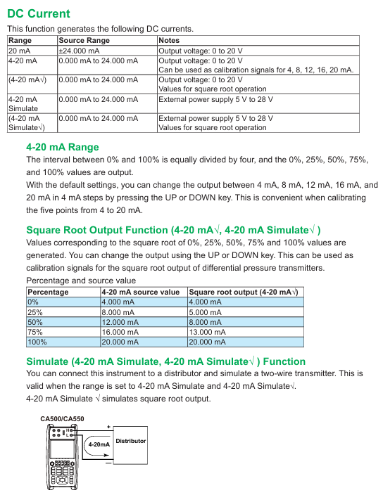
Taking "4-20mA current generation+measurement" as an example, explain the standard operating procedure:
(1) Signal occurrence setting (Function 2)
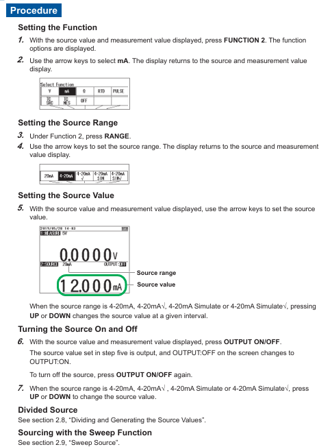
Function selection: Press the Function 2 key, use the directional keys to select mA (current), and press ENTER to confirm.
Range setting: Press the RANGE key, select 4-20mA (default 0%=4mA, 100%=20mA), and press ENTER to confirm.
Parameter adjustment: Set the output value (such as 8mA) through the numeric keys or UP/DOWN keys, press the OUTPUT ON/OFF key to start the output, and the screen will display "OUTPUT: ON".
Scanning function (optional): If step output is required, enter SETUP → Sweep Setup → Step Sweep, set the interval time (such as 10 seconds) and repeat mode (ON/OFF), press the SWEEP key to start step scanning.
(2) Parameter measurement settings (Function 1)
Function selection: Press the Function 1 key, use the directional keys to select mA (current), and press ENTER to confirm.
Range setting: Press the RANGE button, select 50mA (covering 4-20mA measurement requirements), and press ENTER to confirm.
Loop power supply (optional): If measuring a two-wire transmitter, press the LOOP POWER button, and the instrument will output 24VDC loop power while measuring the transmitter output current.
Data reading: The screen displays the measured values in real-time, and pressing the AVERAGE key can view the 5 times moving average, maximum value, and minimum value.
2. Advanced scenario 1: Temperature calibration (thermocouple/RTD)
(1) Thermocouple temperature occurrence (simulating K-type thermocouple)
Function selection: Function 2 → TC SRC (thermocouple occurrence), select K type with the RANGE key, press ENTER to confirm.
Terminal settings: Go to SETUP → Temperature Setup → TC Terminal, select TC-B (banana plug, supports external reference compensation), set TC-B RJC to ON (enables reference compensation).
Temperature setting: Enter the target temperature (such as 200 ℃) through the numerical keys, press OUTPUT ON/OFF to start the output, and the screen will synchronously display the corresponding thermoelectric potential (such as 8.137mV, in accordance with ITS-90 standard).
(2) RTD temperature measurement (PT100)
Function selection: Function 1 → RTD, select PT100 (IEC 60751 standard, -200~800 ℃) with the RANGE key.
Wiring settings: Go to SETUP → Connection Method, select 3W (three wire system, eliminate lead resistance error).
Measurement execution: Connect the PT100 sensor (three wire system), the screen displays the measured temperature, and press the PLAY button to switch the displayed resistance value (e.g. 273.15 Ω corresponds to 0 ℃).
3. CA550 exclusive scenario: HART instrument calibration
Taking the "HART transmitter loop test" as an example, the operation process is as follows:
Communication settings: Press the COM key to enter on-site communication mode, select HART for the HART/BRAN soft key, and set 250 Ω ON/OFF to ON (providing HART communication impedance).
Device connection: Press the CONNECT Device button, and the instrument will automatically connect to the HART device with address 0. After successful connection, the device label and PV value will be displayed.
Loop test: Press the LOOP TEST button to set the target output current (such as 8mA), and the instrument controls the transmitter output through HART commands. At the same time, measure the actual output current and compare the deviation.
Data saving: Enter SETUP → Program Sweep, set calibration points (such as 4/8/12/16/20mA) and tolerances (such as 0.5%), perform scanning, and automatically save data (including device model, serial number, error, and grading results).
Data Management and Remote Control
1. Data storage and export
(1) CA500 Data Management
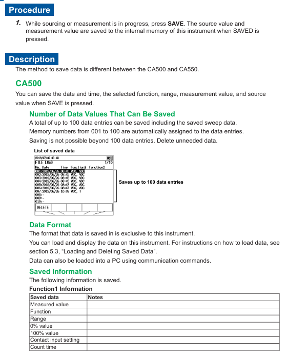
Manual save: During the measurement/occurrence process, press the SAVE button to automatically save the current time, function, range, measurement value/occurrence value, up to 100 records (memory numbers 001~100).
Data reading: Press the LOAD key, select the memory number, and press ENTER to view and save the data. CA500 only supports local viewing of the instrument and needs to be exported to the PC through USB commands.
(2) CA550 Data Management
Auto Save: Enable Data Save=ON during program scanning, and save data in CSV format to internal memory. The folder structure is Root → CalibrationData/WeekData/SaveData (manual save).
USB export: Connect to a PC via a USB cable, and the instrument is recognized as a USB storage device. Copy the CSV file directly to the PC and open it for analysis in Excel (supporting comma/semicolon/tab separation).
2. Remote control (USB communication)
Connect to PC through USB interface and use dedicated instructions to achieve remote control. The core instructions are as follows:
Signal generation: SD20.000 (set current generation value of 20.000mA), SO1 (start output).
Parameter measurement: OD0? (Query Function 1 measurement values), OS? (Query current instrument settings).
Data saving: TS (perform manual saving) OM1? (Read the saved data of memory number 1).
Equipment settings: IO1 (enable 250 Ω communication resistor), VO1 (start 24V circuit power supply).
Communication protocol: Following USB CDC (Communication Device Class), Yokogawa YKCDC USB Driver driver needs to be installed. The PC end sends commands through a serial port tool (such as PuTTY), with a default baud rate of 9600bps.

Precautions and Maintenance
1. Operational safety and accuracy assurance
Output protection: Avoid short circuits when outputting DC voltage in the 30V range, and avoid open circuits when outputting DC current. The instrument has built-in overvoltage/overcurrent protection, and the output needs to be restarted after triggering the protection.
Temperature effect: Preheat for 1 hour before temperature calibration to avoid the internal temperature rise of the instrument affecting the compensation accuracy of the reference end; The fluctuation of environmental temperature should be controlled within ± 1 ℃ (especially for IL measurement).
Wiring specifications: Three wire or four wire system should be preferred for resistance/RT D measurement to reduce lead resistance errors; Thermocouple wiring needs to distinguish between positive and negative poles (TC-B terminal: red positive, black negative).
2. Instrument maintenance
Battery management: The instrument supports dual power supply of battery and USB, and Power Select can set power priority; When the battery is low, the screen prompts that it needs to be charged in a timely manner (charging time is about 4 hours, full battery life is about 8 hours).
Memory cleaning: When CA550 data is full (250 CSV files), it is necessary to manually delete useless files or format the internal memory (MENU → File Format → QUICK, note: formatting will clear all data).
Calibration cycle: It is recommended to calibrate the instrument once a year. You can contact the authorized service center of Yokogawa or refer to the "User Calibration Manual" downloaded from the official website for self calibration (standard calibration source is required).
Common problems and troubleshooting
Possible causes and solutions for the fault phenomenon
After starting the output, there is no signal. The output terminal is not connected to the load, and the range setting is incorrect. Confirm that the load is within the allowable range (such as 4-20mA range load ≤ 20V), and select the correct range again
The temperature measurement deviation is large, and the reference compensation is not enabled. If the thermocouple type is selected incorrectly, enter the Temperature Setup and enable TC-B RJC. Confirm that the thermocouple type is consistent with the actual one (such as K type)
HART communication connection failure: 250 Ω resistor not enabled, device address non-zero. Press the COM key to enable 250 Ω. Confirm that the HART device address is 0 (default) and check the circuit wiring
USB cannot recognize that the driver is not installed and the USB cable has poor contact. Install YKCDC USB Driver, replace the USB cable and reconnect it
Data cannot be saved. Memory is full, file format is incorrect. Delete useless data or format memory. Confirm that the save format is CSV (CA550) or dedicated format (CA500)
- YOKOGAWA
- Reliance
- ADVANCED
- SEW
- ProSoft
- WATLOW
- Kongsberg
- FANUC
- VSD
- DCS
- PLC
- man-machine
- Covid-19
- Energy and Gender
- Energy Access
- Renewable Integration
- Energy Subsidies
- Energy and Water
- Net zero emission
- Energy Security
- Critical Minerals
- A-B
- petroleum
- Mine scale
- Sewage treatment
- cement
- architecture
- Industrial information
- New energy
- Automobile market
- electricity
- Construction site
- HIMA
- ABB
- Rockwell
- Schneider Modicon
- Siemens
- xYCOM
- Yaskawa
- Woodward
- BOSCH Rexroth
- MOOG
- General Electric
- American NI
- Rolls-Royce
- CTI
- Honeywell
- EMERSON
- MAN
- GE
- TRICONEX
- Control Wave
- ALSTOM
- AMAT
- STUDER
- KONGSBERG
- MOTOROLA
- DANAHER MOTION
- Bentley
- Galil
- EATON
- MOLEX
- Triconex
- DEIF
- B&W
- ZYGO
- Aerotech
- DANFOSS
- KOLLMORGEN
- Beijer
- Endress+Hauser
- schneider
- Foxboro
- KB
- REXROTH
- YAMAHA
- Johnson
- Westinghouse
- WAGO
- TOSHIBA
- TEKTRONIX
- BENDER
- BMCM
- SMC
- HITACHI
- HIRSCHMANN
- XP POWER
- Baldor
- Meggitt
- SHINKAWA
- Other Brands
- UniOP
- KUKA
- IBA
- Beckhoff
-
LTI SC52.0040.0012.0000.0 - Servo Drive
-
Lti SC52.0040.0012.0000.0 - Servo Drive
-
Milton Industries LTI Tool By Milton LT1240 - 1/2" Drive Lugnut Remover
-
LTi Drives SO84.200.P030.0000.0-W - Servo Spindle Drive
-
LTI DRIVES LSP08-035-320-30-B0R1PY170 - Servo Motor
-
LTI DRIVES SE84.200.SC00.0001.0-W - Servo Drive
-
Lust CDE34.005.W2.2 - Lti Drives Controller
-
LTi SO84.012.0030.0011.2 - ServoOne Servo Drive
-
LTi Drives SO CM-P.0010.11.00.0 - Servo Drive Controller
-
LTi CDE34.017.W3.0 - Servo Drive
-
LTI Drives CDB32.004, C2.0,SH - Positioning Controller
-
LUST CM-CAN1 - LTi DRIVES Communication Module
-
LTi SO84.012.1030.0000.2 - Servo Drive
-
LTI MOOG CDE54.044 - PITCHMASTER FREQUENCY CONVERTER 181-01019
-
MOOG LTI 181-01019 CDE54.044 - PITCHMASTER FREQUENCY CONVERTER
-
Lust LTi Drives CDE34.010,D2.0 - Servo Drive Controller
-
LTI SO84.032.0003.0101.2 - Servo Drive
-
Seagate 9CC132-302 Harris LTI-CS IRT-34-0021-01 - Hard Drive 160GB
-
LTI SO84.032.0003.0001.2 - Servo Drive
-
LTI SO24.007.0070.0000.1 - SERVO CONTROLLER
-
LTi drive CDA32.003.C3.0.H05-01.PC1 - Servo Drive
-
LTI SO84.016.0030.0000.2 - SERVO CONTROLLER
-
LUST LTI CD A34.008,W1.4, BR - SERVO DRIVE
-
MOOG LTI 181-01019 CDE54.044 - PITCHMASTER FREQUENCY CONVERTER
-
LTI MOOG 181-01019 - PITCH Master Servo Drive CDE54.044
-
LTI SERVO ONE SO84.045.0030.0001.2-W - Drive
-
LUST LTi SO84.032.0040.0000.2 - SERVO ONE DRIVE
-
LTi Drives LSH-074-2-30-3 20/T1,G6.1M - SERVO MOTOR
-
LTI SO84.016.0000.0101.2 - servo drive
-
LTI SA54.0550.0033.0000.0 - Servo Drive
-
LTI SA54.0550.0033.0000.0 - Servo Drive
-
LTI LT 4850 - 3/8" Drive 3-Pc Twist Socket Transmission Drain Plug Removal System
-
LTI Tools LT4400-30 Lock Technology - 3/4" Twist Socket 1/2" Drive Lugnut Remover
-
LTI Tools LT-1400C - 1/2 Drive Wheel Torque Extension Tool
-
LTI Tools LT1250 - 1/2" Drive Dual Sided Socket Lug Nut Remover Tool
-
LTI SO84.032.0003.0101.2 - Servo Drive
-
LTI MOOG 181-01019 - PITCH Master Servo Drive CDE54.044
-
MOOG LTI 181-01019 CDE54.044 - PITCHMASTER FREQUENCY CONVERTER
-
MOOG LTI 181-01019 CDE54.044 - PITCHMASTER FREQUENCY CONVERTER
-
MOOG LTI 181-01019 CDE54.044 - PITCHMASTER FREQUENCY CONVERTER
-
LTI SA54.0550.0033.0000.0 - Servo Drive
-
LTI Tools LT-4800 - 7 Piece Twist Socket 3/8" Drive Oil Drain Plug Removal Set
-
LTI SA54.0550.0033.0000.0 - Servo Drive
-
LTI Drive SO24.007.00300000.0 - Servo Drive
-
LTI TOOLS LTI 1400-I - Drive Wheel Torque Extension
-
LTI Tools LT4400-3 - 3/4" 19mm Twist Socket 1/2" Drive Lugnut
-
LTI TOOLS LTI 1400-BB - Drive Wheel Torque Extension
-
LTI SO84.032.0003.0101.2 - Servo Drive
-
LTI Tools LT-4512 - 3/8" Drive 12mm Twist Socket
-
LTI MOTION Luster SO84.032.0003.0001.2 - Servo Drive
-
LTI Tool By Milton LT1600P - 1" Drive Torx Stick
-
LTI Lust VF1424L,HF,OP2,S56 - Variable Frequency Drive
-
LUST CDA32.004,C1.4,H08,B0 - SERVO DFRIVE CM-CAN1 Module
-
LTI SO84.045.0002.0001.2-W - Drive
-
LTI Lust VF1404M,C9,PT1,BR1 - Inverter Type VF1404M
-
LTI SA54.0550.0033.0000.0 - Servo Drive
-
LTI Tools LT-1400C - 1/2" Drive Wheel Torque Extension
-
Lust LTI DRiVES CDA32.006, C3.0, H09 - Variateur De Fr茅quence Frequency Inverter
-
LTI MOOG CDE54.044 - PITCH master SERVO DRIVE
-
LTI MOOG CDE54.044 - PITCH master SERVO DRIVE
-
LTI SO84.143.0020.0101.2-W - servo drive
-
LTI MOTION SC34.0200.0011.0000.0 - Servo drives
-
LTI SO84.032.0003.0001.2 - Servo Drive
-
LTI DRIVES GmbH MS100 - Assembly Set Mounting Kit
-
LTI SO84.032.0003.0001.2 - Servo Drive
-
LTI SO84.032.0003.0001.2 - Servo Drive
-
LTI MOTION SO84.032.0003.0101.2 - servo drive
-
LTI SO84.032.0003.0101.2 - Servo Drive
-
LTI MOOG CDE54.044 - PITCH master SERVO DRIVE
-
LTI MOTION CDE32.004.C2.4 - Servo drives
-
LTI CDD34.032锛學x.x锛孊R锛孭C1 - Servo Drive
-
Lust LTI DRiVES CDA32.006, C3.0, H09 - Inversor De Frecuencia Frequency Inverter
-
Lust SO84.008.0030.1000.0 - Servo One LTi Drive
-
LTI MOTION SO84.032.0003.0101.2 - Servo drives
-
LUST LTi CDA32.004,C1.4 - SERVO DRIVE
-
LTI MOOG CDE54.044 - PITCH Master SERVO DRIVE
-
LTI KEBA CDB32.004 C2.7, SH - PN: 08673530 Frequency Inverter
-
LTI Tools LT-1400C - 1/2" Drive Wheel Torque Extension
-
LTI LT1400-E - 1/2" Drive Wheel Torque Extension
-
LTI MOOG 181-01019 - PITCH master SERVO DRIVE CDE54.044
-
LTI LSN-097-0510-30-560/T1 - Actuator Motor
-
LTI Tools LT 4800 - 7 Piece 3/8" Drive Twist Socket Oil Drain Plug Removal System
-
LTI DRIVES GmbH MS100 - MONTAGESET Assembly Set Mounting Kit
-
Lti SC52.0040.0012.0000.0 - Servo Drive
-
LTI DRIVES GmbH MS100 - Juego De Montaje Assembly Set Mounting Kit
-
LTi DSM4-14.2-21R83-200 - Drives servomoteur Servo Motor
-
MOOG CDE 54.044.GDA - Pitch Master Industrielle Turbine Lti Drive
-
LTI SO24.004.0030.1000.0 - Servo Drive Controller
-
Lti MOOG CDE54.044 - Pitch Master Servo Drive
-
Lust LTI DRiVES CDA32.006, C3.0, H09 - Inverter
-
LTI MOTION GMBH CDB34.006,W3.0,PC1,H39 - Frequency inverter
-
LTI SO84.032.0003.0001.2 - Servo Drive
-
MOOG CDE 54.044.D - Pitch Master Industrielle Turbine Lti Drive
-
LTI TOOLS LT-1460 - 1/2" DRIVE WHEEL TORQUE EXTENSION KIT 5 PIECE SET
-
Lust Cdb32.003, C2.4 - Lti Drives Servoregulador Frecuencia Servo Controller Inverter
-
Lust LTI DRIVES CDA32.006, C3.0, H09 - Frequency Inverter
-
Lust Lti SO82.004.0030.0000.2 - Servo Drive
-
LTI MOTION SC34.0200.0011.0000.0-SL - Servo drives
-
LTI MOTION SA54.0075.0033.0000.0 - Servo drives
-
LTI MOTION SC32.0075.1011.0000.0 - Servo drives
-
LTI Servo-One Junior SO22.006.0080.1000.0 - Servo Controller Servoregler
-
LUST CDA32.004, C1.4, H08, B0 - Servo Drive & LTI CM-CAN1 Module
-
LTI DRIVES LSP08-035-320-30-B0R1PY170 - Servo Motor
-
LUST LTI CDA32.004,C1.4.H08.B0 - SERVO CONTROLLER DRIVES
-
LUST LTi DRiVES CDS44.072LC1.2 - Servo Drive
-
Lti Servo-One Junior SO22.006.0082.1000.0 - Servo Controller Servoregler
-
LUST CDA32.008,C2.0,HF - Lti DRIVES Spindle Drive Inverter
-
LTI SO22.003.0082.0000.0 - Servo Drives One junior Servo Controller Servoregler
-
Lust Lti Drives CM-CAN1 - Communication Module
-
LUST Lti Drives Vf1202s, G8, I6 - Frequency Inverter Drive
-
LTI DRIVES BR-090.03.540.UR.H38 - Bremswiderstand Brake Resistor
-
LTi DRIVES PM-E40.2DRA054P - Wind Turbine Pitch Control Inverter
-
LTi Drives GmbH br-110.01.540-UR - Brake Resistor
-
LTI Drives LSN-097-0960-30-0560/T1,S4,B - Servo Motor
-
LUST CDA34.006.C2.0 - LTI Drives Servoregler
-
LUST LTI DRIVES SERVO ONE JUNIOR SO24.002.0020.0000.1 - Servo Drive Controller
-
LTI MOTION SO84.032.0003.0001.2 - Servo drives
-
LTI DDTD750V2-120 - IBOP ACTUATOR CYLINDER FOR TOP DRIVE
-
LTI CDE32.004, C2.4 - SERVO DRIVE
-
LUST LTI DRIVES CDD34.017 W3.4PC1 - Servo Drive Controller
-
LTI CDA3208,C3,0,HF - AC SERVO DRIVE
-
LUST LTI DRIVES LSH-074-3-30-560/T1,G6.1S - SERVO MOTOR
-
LUST Lti CDB32.004.C2.4.SH - AC Servo Drive
-
LTi CDA32.006, C3.0, H09 - Servo Drive
-
LTI SO22.003.0010.0000.0 - Servo Drive Servo one junior Servoregler Controller
-
LTi Drives DSM4-14.2-21R83-200 - Servo Motor
-
LUST Lti Drives Lsh-097-1-30-560/T1, 1R - Servomotor
-
LTI 1237 - 7 Piece 1/2" Drive Flip Socket Set

K-JIANG

Add: Jimei North Road, Jimei District, Xiamen, Fujian, China
Tell:+86-15305925923