
K-WANG


YOKOGAWA CW500 Power Quality Analyzer
YOKOGAWA CW500 Power Quality Analyzer
Instrument positioning and core use
CW500 is a portable power quality analyzer that can accurately measure voltage, current, power, harmonics, and power quality events (sudden rise/fall/interruption, transient overvoltage, impulse current, flicker, etc.). It supports various wiring systems from single-phase two wire to three-phase four wire, and is widely used in power quality assessment and problem solving in factory distribution systems, new energy power stations, data centers, and other scenarios.
Core difference models: divided into two categories: with Bluetooth function (- B1, only applicable in Japan, the United States, and Canada) and without Bluetooth function (- B0). The power cord is configured according to regional standards (such as GB standards, VDE standards, etc.), and the corresponding model needs to be selected according to the usage region.
Open box inspection and accessory instructions
1. Packaging content confirmation
After unboxing, it is necessary to verify the instrument model and suffix code (such as power cord standard, Bluetooth function) to ensure consistency with the order. The core accessories are shown in the table below:
Serial number, accessory name, model/specification, quantity description
1 set of voltage probe 98078, including 4 red, white, blue, and black wires (with crocodile clip), to match the terminals according to the wiring color
According to regional standards (such as UL/CSA for - B and GB for - H), one cord with a maximum rated voltage of 250V (125V for some models) needs to be matched with local power grid standards
3 USB cables L3064AD 1 for connecting PC and instrument, supporting data transmission and remote control
4 AA alkaline batteries (LR6) with 6 spare power supplies, with a full charge range of about 3 hours (when the backlight is turned off)
5 SD memory cards 97060 (2GB), 1 card for storing measurement data, supporting FAT16 format
6 portable cases 93046 1 protective instrument from impact and dust
7 Input Terminal Board -1 piece selected by wiring color (6 types), pasted on the top terminal area of the instrument
8 ID tags with 8 colors (red/blue/yellow, etc.) are pasted on both ends of the probe, corresponding to the terminal colors, to avoid wiring errors
9 CDs -1 sheet including application software and electronic manual (PDF)
1 set of 10 manuals including IM CW500-02EN, quick start guide, installation manual, and safety manual
2. Optional accessories (purchased separately)
It mainly includes current clamp probes with different ranges (2A~3000A, such as 2A for 96060 and 3000A for 96066), power adapters (98031, CW500 specific), banana head DIN adapter cables (99073), etc. The appropriate probe should be selected according to the measurement current range.
Safety regulations and operational limitations
1. Safety symbols and warnings
Warning: Refers to the risk of fatal/serious injury, such as prohibition of use in explosive environments, prohibition of unauthorized disassembly of instruments, and power-off and removal of probes before replacing batteries.
CAUTION: It involves the risk of minor injury or equipment damage, such as avoiding short circuits at the metal end of the probe, measuring beyond the range for a long time, and using in humid environments.
Protection level: Double insulation design, measurement category in accordance with IEC61010 standard, voltage limits for different categories are as follows:
CAT IV: 300VAC (applicable to power input terminal)
CAT III: 600VAC (applicable to distribution panels, circuit breakers)
CAT II: 1000VAC (suitable for household appliances and portable tools)
2. Operating environment restrictions
Environmental conditions: working temperature 0~45 ℃, relative humidity ≤ 85% (no condensation); Storage temperature -20~60 ℃, altitude ≤ 2000m, indoor use.
Electromagnetic compatibility: Class A industrial equipment may cause radio interference when used in residential areas, and users need to solve the interference problem themselves; Compliant with standards such as EN 61326-1 and EN 55011 Class A.
Instrument structure and functional layout
1. Name and function of core components
(1) Front panel
Component Function Description
Display screen 3.5-inch color TFT LCD (320 × 240 pixels), displaying measurement data, waveforms, vector graphics, etc
Function keys (F1~F4) execute menu options at the bottom of the screen, such as "Zoom", "Trend", "Customize"
The PRIMT SCREEN key saves the current screen as a BMP file to the SD card
Press and hold the DATA HOLD/KEY LOCK key for 2 seconds to lock all keys, then press and hold again to unlock; Short press to maintain display (measurement continues)
Press and hold the power button to turn on/off, and the interface from the last shutdown will be displayed after turning on
LCD key switches backlight switch, adjusts contrast and brightness
START/STOP key to start/stop data recording, status LED: green light constantly on indicates recording, green light flashing indicates standby
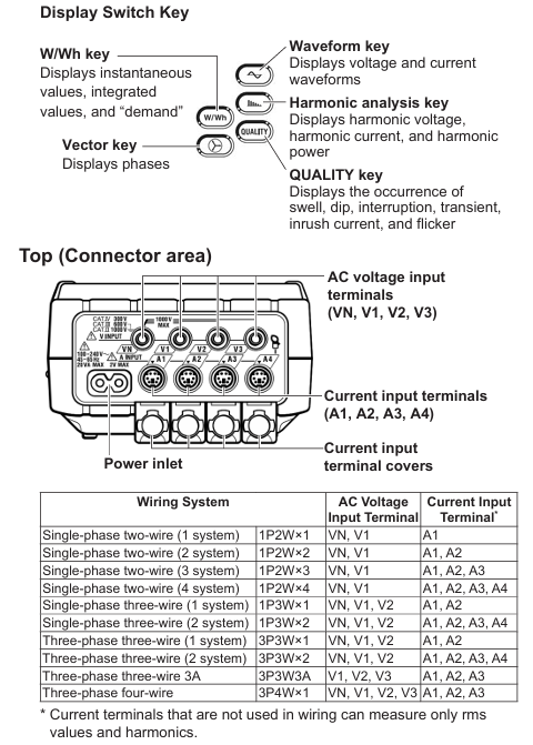
(2) Top terminal area
Voltage input terminals: VN (neutral wire), V1/V2/V3 (phase wire), supporting single-phase to three-phase wiring.
Current input terminals: A1/A2/A3/A4, connected to clamp probes. Unused current terminals can only measure effective values and harmonics.
Power interface: Connect a dedicated power cord and support wide voltage input of 100-240VAC.
(3) Side and back
Side: SD card slot (supporting 2GB SD card), USB Type-B interface (connected to PC), analog input terminal (2-channel, ± 11VDC, monitoring temperature sensor and other signals), digital output terminal (open collector, outputting low level when power quality event triggers).
Back: Battery cover (6 AA batteries), instrument serial number label (to be provided when contacting the dealer).
2. Probe and wiring identification
Voltage probe: equipped with a safety barrier (to avoid finger crossing), connected to the tested circuit at the crocodile clip end, and connected to the instrument voltage terminal at the other end. It needs to be matched with the ID marked color (such as red connected to V1, blue connected to VN).
Clamp probe: The direction of the arrow should be consistent with the current flow direction (otherwise the polarity of the active power will reverse), supporting a range of 2A~3000A. When connecting, it should be aligned with the arrow mark on the instrument current terminal.
Basic operation process
1. Power supply mode setting
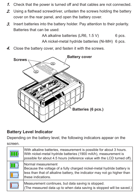
(1) Battery powered
Confirm that the instrument is powered off, use a Phillips screwdriver to open the back battery cover, and insert 6 AA alkaline batteries (or nickel hydrogen rechargeable batteries) according to polarity.
Close the battery cover and tighten the screws. After turning on, the battery icon will be displayed at the top of the screen, with 4 bars indicating full charge and 1 bar indicating low battery (needs to be replaced in a timely manner).
Attention: Nickel hydrogen batteries need to be charged with a dedicated charger, and the instrument does not support charging function; Long term disuse requires removing the battery to avoid leaking and damaging the instrument.
(2) AC power supply
Confirm that the instrument is powered off, connect one end of the power cord to the top power interface of the instrument, and plug the other end into a socket that meets local standards (100-240VAC, 50/60Hz).
After booting up, the AC power icon is displayed at the top of the screen, with a maximum power consumption of approximately 7VA.
2. Preparation before measurement
(1) Paste terminal board and ID mark
Select the input terminal board that matches the wiring color from the accessories (such as TYPE 1: VN=blue, V1=red, V2=green), clean the top terminal area of the instrument, and paste it.
Paste the ID tag on both ends of the probe to ensure consistency with the terminal color (such as connecting the red probe to the V1 terminal), to avoid wiring errors.
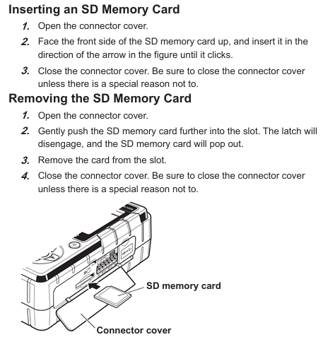
(2) SD card installation
Open the side SD card slot cover, insert the SD card face up (hear a "click" sound to indicate installation), and close the slot cover.
The new SD card needs to be formatted on the instrument (through the SETUP menu), as formatting on a PC may result in abnormal recording; Stop recording before removing the SD card to avoid data damage.
3. Wiring and measurement startup
Taking the "three-phase four wire (3P4W)" wiring as an example, the process is as follows:
Power off confirmation: Ensure that the tested circuit is powered off, remove the instrument power supply and probe.
Voltage wiring: Connect the voltage probe crocodile clip to VN (neutral wire) and V1/V2/V3 (phase wire) respectively, and insert the other end of the probe into the instrument VN and V1/V2/V3 terminals.
Current wiring: Clamp the clamp probe on the outside of the V1/V2/V3 phase line (arrow pointing towards the current flow direction), and insert the probe plug into the A1/A2/A3 terminals accordingly.
Power on and setup: Press and hold the power button to turn on the device, press the SETUP button to enter "Basic Setup", select the wiring system as "3P4W", confirm the voltage range (default 600V), and current clamp model (e.g. 96064 is 500A).
Start recording: Press the START button, the status LED green light stays on, the screen displays "REC", and start recording measurement data; Press the STOP button to stop recording, and the data will be automatically saved to the SD card.
4. Data display and operation
(1) Key function key operation
W/Wh key: Switch between displaying instantaneous values (voltage, current, power), integrated values (electrical energy Wh, varh), and demand values (DEM Target/Guess/Max).
Vector key: Display voltage/current vector diagram, check if the wiring phase is correct (e.g. three-phase voltage phase difference should be 120 °).
Waveform key: Display real-time voltage/current waveforms, switch channels using the directional keys, and adjust the time scale by pressing the F2 key (e.g. 5ms/div).
Harmonic key: displays the harmonic analysis results (1st to 50th harmonics), including THD (total harmonic distortion) and the percentage of voltage/current for each harmonic.
QUALITY key: displays the record of power quality events, such as the occurrence time and value of sudden rise (default 110% rated voltage), sudden drop (default 90% rated voltage), and interruption (default 10% rated voltage).
Core functions and technical parameters
1. Measurement function and scope
Measurement parameter range/range accuracy (typical values)
Voltage (RMS) 600.0V/1000V ± 0.2% reading ± 0.2% range (sine wave, 40~70Hz)
Current (RMS) 2A~3000A (depending on clamp probe) ± 0.2% reading ± 0.2% range+probe accuracy
Active power 2000W~3000kW ± 0.3% reading ± 0.2% range (power factor=1, sine wave)
Frequency 10.00~99.99Hz ± 2dgt (40~70Hz, V1 range 10%~110%)
Harmonic (1~50 times) THD 0.0%~100.0% complies with IEC61000-4-30, Class 3 accuracy
Flashing Pst (short-term) and Plt (long-term) comply with IEC61000-4-15, with a reading of ± 10%
2. Data recording and storage
Record interval: adjustable from 1 second to 30 minutes, supporting manual/continuous/timed recording modes.
Storage media: Built in 4MB flash memory (used without SD card), 2GB SD card (default accessory), saved in CSV format, supports PC analysis later.
Event recording: Automatically record events such as sudden rise, sudden drop, interruption, transient overvoltage, surge current, etc. The trigger threshold can be customized (such as a sudden rise threshold of 110% of the rated voltage).
Common Problems and Maintenance
1. Troubleshooting
Possible causes and solutions for the fault phenomenon
If there is no response when starting up, the battery is dead or the installation is reversed. If the power cord has poor contact, replace the battery and confirm the polarity. Check the power cord connection
No measurement data, probe not connected properly, wiring error, improper range setting. Reconnect the probe, check the terminal color and wiring diagram, and confirm that the range covers the measured value
SD card cannot be read, unformatted, damaged, poor contact. Format SD card on the instrument (SETUP → Save → Format), replace SD card
Record if the SD card is full or the battery is low, delete useless data or replace the SD card, connect to AC power or replace the battery during the recording process
2. Daily maintenance
Calibration cycle: It is recommended to calibrate once a year. You can contact the authorized service center of Yokogawa or refer to the "User Calibration Manual" on the official website for self calibration (standard calibration source is required).
Probe maintenance: Regularly check whether the insulation layer of the probe is damaged and whether the metal end is oxidized; The voltage probe crocodile clip needs to be cleaned to ensure good contact.
Instrument cleaning: Wipe the outer shell with a dry soft cloth and avoid using corrosive solvents such as alcohol and gasoline; If there is dust in the terminal area, it can be blown clean with compressed air.
- YOKOGAWA
- Reliance
- ADVANCED
- SEW
- ProSoft
- WATLOW
- Kongsberg
- FANUC
- VSD
- DCS
- PLC
- man-machine
- Covid-19
- Energy and Gender
- Energy Access
- Renewable Integration
- Energy Subsidies
- Energy and Water
- Net zero emission
- Energy Security
- Critical Minerals
- A-B
- petroleum
- Mine scale
- Sewage treatment
- cement
- architecture
- Industrial information
- New energy
- Automobile market
- electricity
- Construction site
- HIMA
- ABB
- Rockwell
- Schneider Modicon
- Siemens
- xYCOM
- Yaskawa
- Woodward
- BOSCH Rexroth
- MOOG
- General Electric
- American NI
- Rolls-Royce
- CTI
- Honeywell
- EMERSON
- MAN
- GE
- TRICONEX
- Control Wave
- ALSTOM
- AMAT
- STUDER
- KONGSBERG
- MOTOROLA
- DANAHER MOTION
- Bentley
- Galil
- EATON
- MOLEX
- Triconex
- DEIF
- B&W
- ZYGO
- Aerotech
- DANFOSS
- KOLLMORGEN
- Beijer
- Endress+Hauser
- schneider
- Foxboro
- KB
- REXROTH
- YAMAHA
- Johnson
- Westinghouse
- WAGO
- TOSHIBA
- TEKTRONIX
- BENDER
- BMCM
- SMC
- HITACHI
- HIRSCHMANN
- XP POWER
- Baldor
- Meggitt
- SHINKAWA
- Other Brands
- UniOP
- KUKA
- IBA
- Beckhoff
-
LTI SC52.0040.0012.0000.0 - Servo Drive
-
Lti SC52.0040.0012.0000.0 - Servo Drive
-
Milton Industries LTI Tool By Milton LT1240 - 1/2" Drive Lugnut Remover
-
LTi Drives SO84.200.P030.0000.0-W - Servo Spindle Drive
-
LTI DRIVES LSP08-035-320-30-B0R1PY170 - Servo Motor
-
LTI DRIVES SE84.200.SC00.0001.0-W - Servo Drive
-
Lust CDE34.005.W2.2 - Lti Drives Controller
-
LTi SO84.012.0030.0011.2 - ServoOne Servo Drive
-
LTi Drives SO CM-P.0010.11.00.0 - Servo Drive Controller
-
LTi CDE34.017.W3.0 - Servo Drive
-
LTI Drives CDB32.004, C2.0,SH - Positioning Controller
-
LUST CM-CAN1 - LTi DRIVES Communication Module
-
LTi SO84.012.1030.0000.2 - Servo Drive
-
LTI MOOG CDE54.044 - PITCHMASTER FREQUENCY CONVERTER 181-01019
-
MOOG LTI 181-01019 CDE54.044 - PITCHMASTER FREQUENCY CONVERTER
-
Lust LTi Drives CDE34.010,D2.0 - Servo Drive Controller
-
LTI SO84.032.0003.0101.2 - Servo Drive
-
Seagate 9CC132-302 Harris LTI-CS IRT-34-0021-01 - Hard Drive 160GB
-
LTI SO84.032.0003.0001.2 - Servo Drive
-
LTI SO24.007.0070.0000.1 - SERVO CONTROLLER
-
LTi drive CDA32.003.C3.0.H05-01.PC1 - Servo Drive
-
LTI SO84.016.0030.0000.2 - SERVO CONTROLLER
-
LUST LTI CD A34.008,W1.4, BR - SERVO DRIVE
-
MOOG LTI 181-01019 CDE54.044 - PITCHMASTER FREQUENCY CONVERTER
-
LTI MOOG 181-01019 - PITCH Master Servo Drive CDE54.044
-
LTI SERVO ONE SO84.045.0030.0001.2-W - Drive
-
LUST LTi SO84.032.0040.0000.2 - SERVO ONE DRIVE
-
LTi Drives LSH-074-2-30-3 20/T1,G6.1M - SERVO MOTOR
-
LTI SO84.016.0000.0101.2 - servo drive
-
LTI SA54.0550.0033.0000.0 - Servo Drive
-
LTI SA54.0550.0033.0000.0 - Servo Drive
-
LTI LT 4850 - 3/8" Drive 3-Pc Twist Socket Transmission Drain Plug Removal System
-
LTI Tools LT4400-30 Lock Technology - 3/4" Twist Socket 1/2" Drive Lugnut Remover
-
LTI Tools LT-1400C - 1/2 Drive Wheel Torque Extension Tool
-
LTI Tools LT1250 - 1/2" Drive Dual Sided Socket Lug Nut Remover Tool
-
LTI SO84.032.0003.0101.2 - Servo Drive
-
LTI MOOG 181-01019 - PITCH Master Servo Drive CDE54.044
-
MOOG LTI 181-01019 CDE54.044 - PITCHMASTER FREQUENCY CONVERTER
-
MOOG LTI 181-01019 CDE54.044 - PITCHMASTER FREQUENCY CONVERTER
-
MOOG LTI 181-01019 CDE54.044 - PITCHMASTER FREQUENCY CONVERTER
-
LTI SA54.0550.0033.0000.0 - Servo Drive
-
LTI Tools LT-4800 - 7 Piece Twist Socket 3/8" Drive Oil Drain Plug Removal Set
-
LTI SA54.0550.0033.0000.0 - Servo Drive
-
LTI Drive SO24.007.00300000.0 - Servo Drive
-
LTI TOOLS LTI 1400-I - Drive Wheel Torque Extension
-
LTI Tools LT4400-3 - 3/4" 19mm Twist Socket 1/2" Drive Lugnut
-
LTI TOOLS LTI 1400-BB - Drive Wheel Torque Extension
-
LTI SO84.032.0003.0101.2 - Servo Drive
-
LTI Tools LT-4512 - 3/8" Drive 12mm Twist Socket
-
LTI MOTION Luster SO84.032.0003.0001.2 - Servo Drive
-
LTI Tool By Milton LT1600P - 1" Drive Torx Stick
-
LTI Lust VF1424L,HF,OP2,S56 - Variable Frequency Drive
-
LUST CDA32.004,C1.4,H08,B0 - SERVO DFRIVE CM-CAN1 Module
-
LTI SO84.045.0002.0001.2-W - Drive
-
LTI Lust VF1404M,C9,PT1,BR1 - Inverter Type VF1404M
-
LTI SA54.0550.0033.0000.0 - Servo Drive
-
LTI Tools LT-1400C - 1/2" Drive Wheel Torque Extension
-
Lust LTI DRiVES CDA32.006, C3.0, H09 - Variateur De Fr茅quence Frequency Inverter
-
LTI MOOG CDE54.044 - PITCH master SERVO DRIVE
-
LTI MOOG CDE54.044 - PITCH master SERVO DRIVE
-
LTI SO84.143.0020.0101.2-W - servo drive
-
LTI MOTION SC34.0200.0011.0000.0 - Servo drives
-
LTI SO84.032.0003.0001.2 - Servo Drive
-
LTI DRIVES GmbH MS100 - Assembly Set Mounting Kit
-
LTI SO84.032.0003.0001.2 - Servo Drive
-
LTI SO84.032.0003.0001.2 - Servo Drive
-
LTI MOTION SO84.032.0003.0101.2 - servo drive
-
LTI SO84.032.0003.0101.2 - Servo Drive
-
LTI MOOG CDE54.044 - PITCH master SERVO DRIVE
-
LTI MOTION CDE32.004.C2.4 - Servo drives
-
LTI CDD34.032锛學x.x锛孊R锛孭C1 - Servo Drive
-
Lust LTI DRiVES CDA32.006, C3.0, H09 - Inversor De Frecuencia Frequency Inverter
-
Lust SO84.008.0030.1000.0 - Servo One LTi Drive
-
LTI MOTION SO84.032.0003.0101.2 - Servo drives
-
LUST LTi CDA32.004,C1.4 - SERVO DRIVE
-
LTI MOOG CDE54.044 - PITCH Master SERVO DRIVE
-
LTI KEBA CDB32.004 C2.7, SH - PN: 08673530 Frequency Inverter
-
LTI Tools LT-1400C - 1/2" Drive Wheel Torque Extension
-
LTI LT1400-E - 1/2" Drive Wheel Torque Extension
-
LTI MOOG 181-01019 - PITCH master SERVO DRIVE CDE54.044
-
LTI LSN-097-0510-30-560/T1 - Actuator Motor
-
LTI Tools LT 4800 - 7 Piece 3/8" Drive Twist Socket Oil Drain Plug Removal System
-
LTI DRIVES GmbH MS100 - MONTAGESET Assembly Set Mounting Kit
-
Lti SC52.0040.0012.0000.0 - Servo Drive
-
LTI DRIVES GmbH MS100 - Juego De Montaje Assembly Set Mounting Kit
-
LTi DSM4-14.2-21R83-200 - Drives servomoteur Servo Motor
-
MOOG CDE 54.044.GDA - Pitch Master Industrielle Turbine Lti Drive
-
LTI SO24.004.0030.1000.0 - Servo Drive Controller
-
Lti MOOG CDE54.044 - Pitch Master Servo Drive
-
Lust LTI DRiVES CDA32.006, C3.0, H09 - Inverter
-
LTI MOTION GMBH CDB34.006,W3.0,PC1,H39 - Frequency inverter
-
LTI SO84.032.0003.0001.2 - Servo Drive
-
MOOG CDE 54.044.D - Pitch Master Industrielle Turbine Lti Drive
-
LTI TOOLS LT-1460 - 1/2" DRIVE WHEEL TORQUE EXTENSION KIT 5 PIECE SET
-
Lust Cdb32.003, C2.4 - Lti Drives Servoregulador Frecuencia Servo Controller Inverter
-
Lust LTI DRIVES CDA32.006, C3.0, H09 - Frequency Inverter
-
Lust Lti SO82.004.0030.0000.2 - Servo Drive
-
LTI MOTION SC34.0200.0011.0000.0-SL - Servo drives
-
LTI MOTION SA54.0075.0033.0000.0 - Servo drives
-
LTI MOTION SC32.0075.1011.0000.0 - Servo drives
-
LTI Servo-One Junior SO22.006.0080.1000.0 - Servo Controller Servoregler
-
LUST CDA32.004, C1.4, H08, B0 - Servo Drive & LTI CM-CAN1 Module
-
LTI DRIVES LSP08-035-320-30-B0R1PY170 - Servo Motor
-
LUST LTI CDA32.004,C1.4.H08.B0 - SERVO CONTROLLER DRIVES
-
LUST LTi DRiVES CDS44.072LC1.2 - Servo Drive
-
Lti Servo-One Junior SO22.006.0082.1000.0 - Servo Controller Servoregler
-
LUST CDA32.008,C2.0,HF - Lti DRIVES Spindle Drive Inverter
-
LTI SO22.003.0082.0000.0 - Servo Drives One junior Servo Controller Servoregler
-
Lust Lti Drives CM-CAN1 - Communication Module
-
LUST Lti Drives Vf1202s, G8, I6 - Frequency Inverter Drive
-
LTI DRIVES BR-090.03.540.UR.H38 - Bremswiderstand Brake Resistor
-
LTi DRIVES PM-E40.2DRA054P - Wind Turbine Pitch Control Inverter
-
LTi Drives GmbH br-110.01.540-UR - Brake Resistor
-
LTI Drives LSN-097-0960-30-0560/T1,S4,B - Servo Motor
-
LUST CDA34.006.C2.0 - LTI Drives Servoregler
-
LUST LTI DRIVES SERVO ONE JUNIOR SO24.002.0020.0000.1 - Servo Drive Controller
-
LTI MOTION SO84.032.0003.0001.2 - Servo drives
-
LTI DDTD750V2-120 - IBOP ACTUATOR CYLINDER FOR TOP DRIVE
-
LTI CDE32.004, C2.4 - SERVO DRIVE
-
LUST LTI DRIVES CDD34.017 W3.4PC1 - Servo Drive Controller
-
LTI CDA3208,C3,0,HF - AC SERVO DRIVE
-
LUST LTI DRIVES LSH-074-3-30-560/T1,G6.1S - SERVO MOTOR
-
LUST Lti CDB32.004.C2.4.SH - AC Servo Drive
-
LTi CDA32.006, C3.0, H09 - Servo Drive
-
LTI SO22.003.0010.0000.0 - Servo Drive Servo one junior Servoregler Controller
-
LTi Drives DSM4-14.2-21R83-200 - Servo Motor
-
LUST Lti Drives Lsh-097-1-30-560/T1, 1R - Servomotor
-
LTI 1237 - 7 Piece 1/2" Drive Flip Socket Set

K-JIANG

Add: Jimei North Road, Jimei District, Xiamen, Fujian, China
Tell:+86-15305925923