
K-WANG


YOKOGAWA CENTUM CS 1000 Distributed Control System Control Function
YOKOGAWA CENTUM CS 1000 Distributed Control System Control Function
Product core positioning
CENTUM CS 1000 is a distributed control system developed by Yokogawa for small and medium-sized factories, with the core goal of reducing total cost of ownership (TCO) while balancing high functionality and maintainability. The design concept is to integrate the high-quality control functions of the CENTUM CS series that have been verified on site, strengthen the communication adaptation capabilities with various subsystems such as programmable logic controllers (PLCs), and solve the core pain points of small and medium-sized factories in control system deployment and maintenance through innovative technologies such as engineering process simplification, communication flexibility, and test virtualization.
System core function configuration
(1) Overall architecture of control function
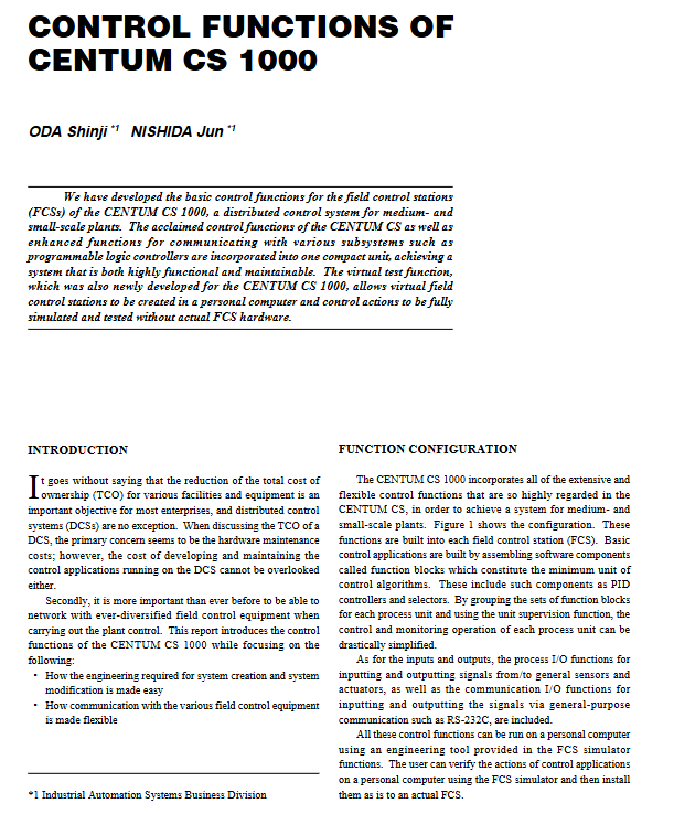
The system control function is highly integrated into each field control station (FCS), with functional blocks as the core to build basic control applications, forming a complete functional system covering control, input/output, management and monitoring. The specific architecture is as follows:
Specific description of the core components of the functional hierarchy
The minimum unit of the core control component function block control algorithm, including basic components such as PID controller and selector, supporting modular assembly
Expansion control module covers various control blocks including regulation control block, sequence control block, SFC (Sequential Function Diagram) block, calculation block, and panel block, adapting to diverse control requirements
The auxiliary management function unit monitoring function is grouped by process unit management function blocks, greatly simplifying the control and monitoring operations of single process units
The status feedback function sequence message and alarm provide real-time feedback on the system's operating status, prompt abnormal information in a timely manner, and ensure operational safety
Universal control function universal switch provides standardized operation interface, suitable for conventional control scenarios
Input/output function process I/O implementation and signal input/output with general sensors and actuators, supporting data exchange of field devices
Input/output function communication I/O achieves signal transmission with external devices through universal communication interfaces such as RS-232C
(2) Reliability assurance design
The system continues the mature synchronous hot standby system of the CENTUM CS series, which is the core of ensuring control continuity
Working principle: The FCS operating system adopts a synchronous running mode between the primary and backup CPUs. When the primary CPU is working normally, the backup CPU synchronizes data in real time; When the main CPU stops due to a sudden failure, the backup CPU seamlessly takes over control tasks without interrupting control actions
Applicable scenarios: Especially suitable for batch production processes guided by sequence control, even during the switching process of duplex control processors, it can maintain control status continuously, avoiding production losses caused by downtime
Engineering Efficiency Optimization: FCS Template Technology
(1) Design background and pain points
The control application is composed of multiple functional blocks, but different functional blocks have significant differences in the internal resources (such as memory) and CPU load requirements of FCS. However, the memory resources of FCS are limited. If functional blocks are combined in an unordered manner, engineers need to have rich experience, estimate resource usage and CPU load in advance, and avoid exceeding the system's carrying capacity. This undoubtedly increases the complexity and threshold of engineering design.
(2) Core Design and Advantages of FCS Template
1. Template types and adaptation scenarios
Yokogawa provides users with three types of preset database templates that accurately match typical application scenarios for small and medium-sized factories:
Adjustment control template: adapted to parameter adjustment scenarios of continuous processes (such as temperature, pressure, flow rate adjustment)
Sequence control template: adapted to batch production scenarios executed according to fixed processes (such as chemical batching, product assembly)
Monitoring Template: Suitable for scenarios that only require data collection and status monitoring (such as device operation status monitoring)
2. Core technical features
Intelligent resource allocation: The template has a built-in optimized database configuration that automatically allocates FCS memory resources based on functional block types, ensuring optimal resource utilization
Strict load control: The preset configuration strictly controls the CPU load to not exceed the limit, eliminating the need for users to manually calculate and reducing the difficulty of engineering design
Ready to use: Users can directly select corresponding templates based on actual application scenarios, without the need to build functional block combinations from scratch, greatly reducing the project cycle
On site communication flexibility design: adaptable to diverse devices
In response to the industry pain points of dispersed on-site control equipment, diverse data types, and inconsistent communication interfaces and protocols, CENTUM CS 1000 achieves flexible adaptation through two core designs:
(1) Separation of communication function and control application
1. Architecture design logic
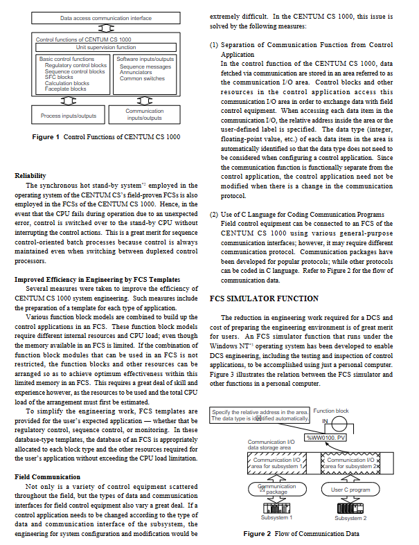
Data storage isolation: External data obtained through communication is uniformly stored in a separate "communication I/O area", which is divided into sub areas according to subsystems (such as subsystem 1 communication I/O area, subsystem 2 communication I/O area)
Data access method: Control the control block in the application to access the data in the communication I/O area (such as% WW0100. PV) through "relative address" or "user-defined tag", without paying attention to the physical source of the data
Automatic data type recognition: The system automatically recognizes the type of each data item (integer, floating point, etc.) in the communication I/O area, and users do not need to manually set the data type when configuring control applications
2. Core advantages
Protocol independence: When the communication protocol is changed, only the communication module configuration needs to be adjusted without modifying the control application, reducing system modification and maintenance costs
Reduce coupling: control logic and communication logic are decoupled to improve system stability and reduce the impact of single module failure on the overall system
(2) C programming language adapted to multiple protocols
1. Protocol adaptation plan
Common protocols: Yokogawa has developed ready-made communication packages for mainstream communication protocols in the industrial field, which users can directly choose and quickly complete equipment docking
Special protocol: For niche or customized protocols, support users to develop communication programs through C language coding to achieve personalized adaptation
2. Communication data flow
On site equipment/subsystems are connected to FCS through a common communication interface
Communication program (ready-made communication package or user C language program) retrieves data and stores it in the communication I/O area
Control applications to access communication I/O areas through addresses or labels to achieve data exchange
Control instructions are transmitted in reverse to on-site devices/subsystems through the same path
Innovative virtual testing function: deep analysis of simulator system
(1) Design Objective
Without the need to build a complete physical FCS hardware environment, the design, testing, and verification of control applications can be completed solely through a personal computer (PC), reducing the cost of building engineering environments and improving project implementation efficiency.
(2) FCS Simulator: Core Virtual Testing Tool
1. Basic configuration
Operating environment: Windows NT operating system
Run mode: Run as an independent process, read the control application definition file generated by the engineering function
2. Core functions
Control action simulation: Fully replicate the control logic and execution process of actual FCS to ensure that test results are consistent with actual operation
Communication mechanism: Through "simulating internal VLnet communication", interaction with PC side operation monitoring function (HIS function) and testing function is achieved. The operation logic is completely the same as connecting to the actual FCS, and users do not need to learn new operation methods separately
3. Internal operating mechanism
Modular design: Each FCS functional task (such as control tasks, communication tasks, trend tasks) is encapsulated as a dynamic link library (DLL) and loaded in thread form during runtime
Kernel adaptation: Built in FCS kernel simulation function (also encapsulated as DLL), its interface is completely consistent with the actual FCS kernel, ensuring the reusability of task source code and guaranteeing functional equivalence
Thread scheduling: After a thread calls the kernel simulation function, it triggers scheduling (scheduling point), and switches threads through the "suspend/resume" command of the Win32 API - the current thread first resumes other suspended threads, and then suspends itself to ensure the orderly execution of multitasking
Interrupt handling: Independent interrupt threads use Windows messages as trigger signals to pause the current task, execute interrupt handling, and resume scheduling after receiving the message, ensuring real-time interrupt response
(3) Inter Station Communication Simulator: Multi FCS Collaborative Testing Tool
1. Original design intention
Support control application testing that requires data interaction between multiple FCS, enabling multi-user parallel system engineering and improving overall design efficiency.
2. Working principle
Data reception: Receive all communication data packets sent by the FCS simulator to other FCS
Data processing:
When receiving data setting commands, save the corresponding request values
When receiving a data read command, return the preset response value
Interactive interface: Support users to view saved request values and set response values through a graphical user interface (GUI), with intuitive and convenient operation
3. Core advantages
Without the need to deploy multiple physical or virtual FCS, cross FCS control application testing can be completed without increasing the existing CPU load, significantly reducing the cost and complexity of multi system collaborative testing.
(4) Overall collaborative process of simulator system
Engineers design control applications through PC engineering functions and generate control application definition files
The FCS simulator loads the definition file and simulates the actual execution of control actions by FCS
If multiple FCS data interactions are involved, start the inter station communication simulator to simulate the response logic of other FCS
The operation monitoring function and testing function simulate internal VLnet communication and interact with the FCS simulator to conduct application testing
After the testing is completed, the control application can be directly deployed to the actual FCS without additional modifications
Core values and future prospects of the system
(1) Summary of Core Values
Specific manifestation of value dimension
Cost optimization: 1. Virtual testing function reduces the cost of building engineering environments; 2. FCS templates simplify the design process and reduce labor costs; 3. Communication and control separation design reduces maintenance costs
Efficiency improvement 1. Template based engineering design shortens project cycle; 2. Multi user parallel testing improves project implementation efficiency; 3. Control the application of "one-time design, two-way deployment" (simulator and actual FCS) to reduce repetitive work
Strong adaptability: 1. Supports multiple communication interfaces and protocols, and adapts to dispersed and diverse on-site devices; 2. Three types of FCS templates cover mainstream application scenarios in small and medium-sized factories
High reliability synchronous hot standby system ensures uninterrupted control in case of CPU failure and adapts to critical scenarios such as mass production
(2) Future Technology Outlook
The document proposes that future control systems need to have open interfaces and cross platform features that are consistent with human-machine interfaces and engineering functions. The simulator technology and enhanced on-site communication capabilities of CENTUM CS 1000 lay the foundation for subsequent technological development
Expansion direction 1: Develop FCS software running on PC to achieve direct control of industrial processes through PC
Expansion direction 2: Develop gateway functions based on existing communication interfaces to achieve interconnectivity among multiple systems
Expansion direction 3: Upgrade the enhanced on-site communication function to a high reliability gateway, adapting to more complex industrial network architectures
Applicable scenarios and industry adaptation
Target scenarios: Continuous process control, batch production sequence control, equipment status monitoring, and other scenarios for small and medium-sized factories
Applicable industries: chemical, pharmaceutical, food and beverage, small-scale electricity, building materials, etc. industries that are sensitive to control system costs, have diverse equipment types, and limited engineering resources
Core adaptation requirements: Application scenarios that require simplification of engineering design, reduction of maintenance costs, adaptation to diverse field devices, and certain requirements for control continuity
- YOKOGAWA
- Reliance
- ADVANCED
- SEW
- ProSoft
- WATLOW
- Kongsberg
- FANUC
- VSD
- DCS
- PLC
- man-machine
- Covid-19
- Energy and Gender
- Energy Access
- Renewable Integration
- Energy Subsidies
- Energy and Water
- Net zero emission
- Energy Security
- Critical Minerals
- A-B
- petroleum
- Mine scale
- Sewage treatment
- cement
- architecture
- Industrial information
- New energy
- Automobile market
- electricity
- Construction site
- HIMA
- ABB
- Rockwell
- Schneider Modicon
- Siemens
- xYCOM
- Yaskawa
- Woodward
- BOSCH Rexroth
- MOOG
- General Electric
- American NI
- Rolls-Royce
- CTI
- Honeywell
- EMERSON
- MAN
- GE
- TRICONEX
- Control Wave
- ALSTOM
- AMAT
- STUDER
- KONGSBERG
- MOTOROLA
- DANAHER MOTION
- Bentley
- Galil
- EATON
- MOLEX
- Triconex
- DEIF
- B&W
- ZYGO
- Aerotech
- DANFOSS
- KOLLMORGEN
- Beijer
- Endress+Hauser
- schneider
- Foxboro
- KB
- REXROTH
- YAMAHA
- Johnson
- Westinghouse
- WAGO
- TOSHIBA
- TEKTRONIX
- BENDER
- BMCM
- SMC
- HITACHI
- HIRSCHMANN
- XP POWER
- Baldor
- Meggitt
- SHINKAWA
- Other Brands
- UniOP
- KUKA
- IBA
- Beckhoff
-
ADLINK PCI-7433 - switch value acquisition card Isolated Digital Input Card
-
ADLINK PCI-9112 - 51-12252-0D20 Multi-Function Data Acquisition Card
-
ADLINK NUPRO-A301 REV:1.4 - industrial control motherboard PICMG Full-Size SBC
-
ADLINK 51-18502-0A10 - Frame Grabber Image Acquisition Interface Card
-
ADLINK PCI-7296 - 51-12009-0A50 PCB-I-E-925=6DX1 96-CH Parallel Digital I/O Board
-
ADLINK PCI-8132 GP A2 - Motion Control Card 2-Axis Servo & Stepper Controller
-
ADLINK PCI-7442 - switch quantity card data acquisition card 64-CH Isolated Card
-
ADLINK HPX-13S4 - baseboard PICMG 1.3 Passive Backplane Chassis Baseplate
-
ADLINK NuPRO-590 / NTC-567-ZM-F36 - Single Board Computer PCB-I-E-1853=9L21 Half-Size SBC
-
ADLINK PCIe-8332 - 16-axis plate Motion Control Hardware Card
-
ADLINK NuPRO-775 REV.B1 - motherboard Pentium 4 Full-Size PICMG SBC
-
ADLINK PXI-3920 - Embedded Controller 3U PXI cPCI System Intelligence Board
-
ADLINK PCI-8134 - driver card motion control card 4-Axis Controller Board
-
ADLINK HSL-DI32-M-N-011 / HSL-TB32-M-DIN - Digital Input & Base Module PLC Distributed I/O System
-
ADLINK PCI-6216V-206 / PCI-208V 009 - 16 CH 16bit analog output card
-
ADLINK NuPro-E330 - 51-41805-0A20 PCB Single Board Computer Host Board
-
ADLINK PCI-1622C - Card 8-Port RS-232/422/485 PCI Serial Communication Board
-
ADLINK PCIe-7432 - 51-18402-0A10 Carte PCIe Avec Plage D'Entrée Élevée Isolated DIO Card
-
ADLINK PCI-7250 - PCI Acquisition Card 8-CH Relay Output Isolated DI Card
-
ADLINK PCI-7230 - 32-CH Isolated Digital I/O Card
-
ADLINK PCI-8164 - PCB 4-Axis Motion Controller Card
-
ADLINK PCI-7854 - Collection card High-Speed Link Distributed Motion Controller
-
ADLINK NuPRO-935A/LV - industrial control computer motherboard Full-Size PICMG SBC
-
ADLINK IMB-M40H - motherboard IH61-AA4 1155 LGA1155 Micro-ATX Mainboard
-
ADLINK PCI-7248 - Linhua 51-12006-0A40 48-CH Parallel Digital I/O Card
-
ADLINK HPCI-14S12U - Linhua industrial computer baseboard Passive Backplane
-
ADLINK PCI-8132 Rev.A2 - 2-Axis Servo & Stepper Motion Controller Card
-
ADLINK ACL-8111 - ISA card Multi-Function DAQ Card
-
ADLINK ACL-8111 - ISA card Multi-Function Data Acquisition Board
-
ADLINK PCI-7200 REV.A3 - Digital I/O card 12MB/s High-Speed Parallel Digital I/O
-
ADLINK PCI-7296 REV.A3 - 96-CH High-Density Opto-Isolated DIO Card
-
ADLINK PCI-7434 - 64-CH Isolated Digital Output Card
-
ADLINK M-342 - atx motherboard Industrial PC Mainboard
-
ADLINK NuPRO-935ADV (A) 1.9 - CPU Board Intel Core 2 Quad CPU Q9500 2.83GHz PICMG Board
-
ADLINK NUPRO-935A/DV - motherboard dual network port 51-41802-0A10 CPU Board
-
ADLINK PCI-RTV24 - image capture card Analog Video Frame Grabber Board
-
ADLINK HPX-13S4 - device baseboard PICMG 1.3 Passive Backplane Chassis Baseplate
-
ADLINK PCI-8134A - control card 4-Axis Motion Controller Card
-
ADLINK ACL-7130 REV. B2 - industrial control capture card Isolated Digital I/O Board
-
ADLINK EBP-13E2 - Industrial Backplane Board Passive Backplane Baseboard
-
ADLINK NuPRO-935ADV (A) 1.9 - CPU Board Intel Core 2 Quad CPU Q9500 2.83GHz PICMG SBC
-
ADLINK PCI-8134A - motion control card 4-Axis Pulse-Train Controller Card
-
ADLINK PCI-9112 REV A.1 - Multi Function DA&C Board Data Acquisition Card
-
ADLINK 51-12001-0C20 - Circuit Board Multi-Function Data Acquisition Hardware
-
ADLINK PCI-7300A - 80-CH High-Speed Digital I/O Card
-
ADLINK PCI-7230 - 16-CH Isolated Digital Input Output Card
-
ADLINK DIN-814-GP - motion control module Interface Terminal Block
-
ADLINK NUPRO-A40H - 51-41807-1A20 Industrial Control Motherboard LGA1155
-
ADLINK PCI-7433 rev A2 - Isolated Digital Input Card
-
ADLINK NuPRO-780 - Pentium III 800 512 MB SBC NuPRO780 51-41309-0B2 Single Board Computer
-
ADLINK PCI-7853 / PCI-7854 - Acquisition card High-Speed Link Control Card
-
ADLINK NUPRO-852 / NUPRO-852LV - Industrial motherboard Full-Size PICMG CPU Board
-
ADLINK NuPRO-842LV/P - 51-41360-0B30 Industrial Motherboard Half-Size PICMG SBC
-
ADLINK PCI-FIW64 - 4/2 Channel IEEE1394B Image Capture Card Frame Grabber
-
ADLINK PCI-7851 Rev A1.1 - HSL system card High-Speed Link Master Controller
-
ADLINK PCI-7230 - 51-12003-0A50 card 32-CH Isolated Digital I/O Card
-
ADLINK NuPRO-841REV:1.0 - Industrial CPU Board Mainboard
-
ADLINK NuPRO-841 REV:1.0 - motherboard Industrial Control PC Mainboard
-
ADLINK PCI-8256 - 8-Axis Advanced Motion Control PCI Board
-
ADLINK PCI-6S / PCI6S - Backplane 6-Slot Passive Backplane Board
-
ADLINK PCI-7234 REV B3 - 32-CH Isolated Digital Output PCI Card
-
ADLINK PCI-8213 - HannStar MV-4 51-45003-0b4 Board
-
ADLINK PCI-7233 - 51-12004-0a20 board PCI7233 32-CH Isolated Digital Input Card
-
ADLINK PCI-7851 - 006 51-24003-0B20 High-Speed Link Master Motion Control Card
-
ADLINK PCI-7432 - 64-CH Isolated Digital I/O PCI Cards
-
ADLINK LPCI-3488 - Card Low Profile IEEE-488 GPIB Interface Card
-
ADLINK HPCI14S REV.B1 - industrial control computer base plate Passive Backplane
-
ADLINK NEON-1020 - Industrial camera Smart Camera Vision System
-
ADLINK PCI-7432 - Isolated Digital I/O PCI Card 64-CH
-
ADLINK Pcm-7250+ - 8-Ch Relay Outputs & 8-Ch Isolated DI Module PC/104
-
ADLINK CPCI-7841 - DUAL-PORT ISOLATED CAN INTERFACE CARD CompactPCI
-
ADLINK PCI-3488 / PCI-GPIB - PCI IEEE-488 GPIB Interface Card
-
ADLINK PCI-1711U - Card Multi-Function Data Acquisition Board
-
ADLINK NUPRO-A301 - REV:1.1 1.2 1.4 PICMG Full-Size Single Board Computer
-
Adlink DIN-50S-01 - PLOTECH 51-14024-0A40 50-pin Wiring Terminal Board
-
Chroma 52962 / 58183 - PXI Optical Spectrometer carrier adapter Card
-
ADLINK PCI-6208V - PCI DATA ACQUISITION & RECORDING CARD 8-CH Analog Output
-
ADLINK HSL-DI32-DB-N - Industrial Control Board Distributed Digital Input Module
-
ADLINK HSL-AO4-U - 4-CH HIGH SPEED LINK ANALOG OUTPUT MODULE Distributed I/O
-
ADLINK PCI-7396 - 0050 GP 51-12012-0B20 96-CH High-Speed Digital I/O Card
-
ADLINK NUPRO-935A/DV - 51-41802-0A10 motherboard Industrial CPU Single Board Computer
-
ADLINK PCI-9111 DG - Industrial Acquisition Card Multi-Function DAQ Card
-
ADLINK NuPRO-E315 - industrial computer motherboard Intel Atom SHB SBC
-
ADLINK NUPRO-406 REV:B1 - Industrial Control Motherboard Full-Size PICMG CPU Board
-
ADLINK NuPRO-E330 - motherboard Industrial Control System Host Board PICMG 1.3
-
ADLINK ACL-6128A 103 - 51-11002-1A4 2-CH Isolated Analog Output Card
-
XTRAMUS cPS-H325/AC - POWER SUPPLY NUSTREAMS 600 NETWORK TESTING EQUIPMENT Power Module
-
ADLINK DIN-814P-A4 - 51-14056-0A10 Terminal Block Motion Control Breakout Board
-
ADLINK TB-24P/24-01 - 24-Channel Card Terminal Breakout Board
-
ADLINK PCI-7251 - 51-12008-0A30 PCI7251 8-CH Relay Output Isolated Digital Input Card
-
ADLINK HSL-TB64-DIN REV A1 / HSL-DO32-DB-N - 2ea Board Breakout Terminal Board Distributed I/O Module
-
ADLINK NuPRO-865 REV 3.0 - industrial computer motherboard Full-Size PICMG SBC
-
ADLINK NUPRO-A40H - motherboard 51-41807-1A30 OSP H61 Industrial PC Mainboard
-
ADLINK LPCI-3488A - PCI Card 51-12801-0A30 GPIB Interface Card
-
ADLINK DIN-825-4P0 - 51-14085-0A30 Terminal Printed Circuit Board Breakout Block
-
ADLINK IMB-T10/D2550 V - MOTHER BOARD 80-PXG160-A1A01 IMB-T10-M2G-S32G Industrial Mainboard
-
ADLINK PCI-8144N - Motion Control card Stepper Motor Controller
-
ADLINK PCI-7433 - Digital acquisition card Isolated Digital Input Card
-
ADLINK PCI-9112 DG - Data Acquisition card 51-12252-0D20 Multi-Function DAQ
-
ADLINK IMB-M40H - motherboard IH61-AA4 1155 LGA1155 Micro-ATX Mainboard
-
ADLINK TB-24P/24-01 - Carte 24 voies Terminal Breakout Board Connector Module
-
ADLINK HSL-D16DO16-M-NN - Distributed Discrete Input Output I/O Module
-
ADLINK PCI-7248 - PCI CARD 51-12006-0A40 48-CH Parallel Digital I/O Board
-
ADLINK HSL-DI32-DB-N - Industrial Control Board Distributed I/O Digital Input Module
-
ADLINK PCI-7433 - Pci 7433 Isolated Digital Input Card
-
ADLINK PCI-6208V - 008 Data acquisition card 8-CH Analog Output Card
-
ADLINK IH61-AA4 - industrial motherboard LGA1155 Micro-ATX Mainboard
-
ADLINK PXI-3920 - PXI 3U cPCI Industrial Controller Embedded System CPU Board
-
ADLINK PCI-6308 - Analog Output DAQ Card Isolated Voltage Output Card
-
ADLINK PCI-7200 - data acquisition card REV.A3 High-Speed Parallel DIO Card
-
ADLINK NuPRO-E315 - Industrial Control Computer Motherboard PICMG 1.3 SHB SBC
-
ADLINK PCI-1610C - Card 4-Port Isolated RS-232 PCI Serial Communication Card
-
ADLINK PCI-1716 - Card High-Resolution Multi-Function DAQ Card
-
ADLINK MI-965 - Industrial Mini-ITX Motherboard CPU Board
-
ADLINK PCI-1610A - Card 4-Port RS-232 PCI Serial Communication Card
-
ADLINK cBP-3208/3208R - CPCI Board 3U 8-Slot CompactPCI Backplane
-
ADLINK PCI-8134A - 51-12421-0A10 4-Axis Motion Controller Card
-
ADLINK PCI-8164 - Motion Control Card 4-Axis Advanced Controller Card
-
ADLINK NUPRO-935A/DV - motherboard dual network port 51-41802-0A10 CPU Board
-
ADLINK PCI-7248 - 51-12006-0A40 acquisition card 48-CH Parallel DIO Card
-
ADLINK PCI-7443 - 51-12022-0A10 BOARD 128-CH Isolated Digital Input Card
-
ADLINK DIN-825-GP4 - Terminal Block Interface Board Breakout Module
-
ADLINK PCI-7248 - Card 48-CH Parallel Digital I/O Card
-
ADLINK NUPRO-865 REV :3.0 - industrial motherboard Intel Pentium 4 CPU Board
-
ADLINK PCI-9113A - Isolated Analog Input Data Acquisition Card
-
ADLINK HPCI-8S4 - REV.B2 Industrial Control Base Plate Passive Backplane
-
ADLINK M-342 - atx motherboard Industrial PC Mainboard
-
ADLINK PCI-RTV24 - image capture card Analog Video Frame Grabber Board

K-JIANG

Add: Jimei North Road, Jimei District, Xiamen, Fujian, China
Tell:+86-15305925923