
K-WANG


Yokogawa CENTUM VP series terminal block
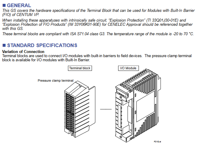
Applicable system: Designed specifically for the Yokogawa CENTUM VP control system, only compatible with FIO modules with built-in In Barrier in this system
Core function: To achieve stable circuit connection between I/O modules with built-in barriers and field devices, playing a role in signal conversion, fixed wiring, and ensuring transmission reliability. It is widely used in signal acquisition and control scenarios of industrial automation
Yokogawa CENTUM VP series terminal block
Product Core Overview
Product type: Pressure Clamp Terminal Block, a key intermediate component for signal transmission in industrial control systems
Applicable system: Designed specifically for the Yokogawa CENTUM VP control system, only compatible with FIO modules with built-in In Barrier in this system
Core function: To achieve stable circuit connection between I/O modules with built-in barriers and field devices, playing a role in signal conversion, fixed wiring, and ensuring transmission reliability. It is widely used in signal acquisition and control scenarios of industrial automation
Compliance standard: Compliant with ISA S71.04 class G3 standard, which specifies requirements for the environmental adaptability and safety performance of industrial process measurement and control equipment, ensuring stable operation of terminal blocks in complex industrial environments
Temperature adaptation range: -20 ℃ to 70 ℃, covering the temperature conditions of most industrial sites (such as factory workshops, control rooms, outdoor equipment areas, etc.), with strong environmental adaptability
Model system and core specifications
(1) Model classification logic
This series of terminal blocks is divided into two core series based on redundancy design. Each series is subdivided into specific models according to application types. The suffix code for all models is fixed at -0, with no other optional configurations. The classification logic is clear, making it easy for users to quickly select according to their actual needs
Single series: The model suffix is "S", suitable for conventional industrial scenarios without redundancy requirements, with a simple structure and controllable cost
Dual Redundancy Series: The model suffix is "D" and is suitable for critical industrial scenarios that require extremely high system stability and reliability (such as core control links in industries such as chemical, power, and petroleum). The dual redundancy design ensures signal continuity in the event of a failure
(2) Detailed explanation of core specifications for all models
Model Application Type Channel Number Adaptation I/O Module Name Weight Core Adaptation Scenario
ATSA3S Analog Input (Single) 8-Point (8-Channel) ASI133 0.2 kg Analog Signal Acquisition in Conventional Scenarios, such as Input of Continuous Variables such as Temperature, Pressure, Flow, etc
ATSA3D analog input (Dual Redundant) 8-Point (8-channel) ASI133 analog signal acquisition under critical scenarios of 0.3 kg, ensuring uninterrupted signal acquisition, such as temperature acquisition of chemical reaction kettle
ATSS3S analog output (Single) 8-Point (8-channel) ASI533 0.2 kg analog signal output in conventional scenarios, such as controlling valve opening, adjusting pump speed, etc
ATSS3D analog output (Dual Redundant) 8-Point (8-channel) ASI533 analog signal output under critical scenarios of 0.3 kg, such as emergency stop control signal and core equipment speed control signal output
ATST4S thermocouple/mV (Single) 16 Point (16 channel) AST143 0.2 kg Temperature measurement signal or millivolt level small signal acquisition for thermocouples in conventional scenarios, such as furnace temperature and pipeline temperature monitoring
ATST4D thermocouple/mV (Dual Redundant) 16 Point (16 channel) AST143 high-precision temperature or small signal acquisition in critical scenarios of 0.3 kg, such as temperature monitoring in aerospace component processing
ATSR3S RTD/PAT (Single) 8-Point (8-Channel) ASR133 0.2 kg Thermal Resistance (RTD) temperature measurement or Potentiometer (POT) signal acquisition in conventional scenarios, such as equipment bearing temperature monitoring
ATSR3D RTD/PAT (Dual Redundancy) 8-Point (8-channel) ASR133 high-precision temperature or potentiometer signal acquisition in critical scenarios of 0.3 kg, such as temperature monitoring of nuclear power equipment
ATSB4S Digital Input (Single) 16 Point (16 Channel) ASD143 0.2 kg Digital Signal Input for Conventional Scenarios, such as Limit Switch Status and Equipment Operation Status (Run/Stop) Detection
ATSB4D Dual Redundant 16 Point ASD143 0.3 kg digital signal input for critical scenarios, such as emergency stop button signal and safety door switch status detection
ATSD3S digital output (Single) 8-Point (8-channel) ASD533 0.2 kg digital signal output in conventional scenarios, such as control indicator light on/off, relay on/off, small pump start/stop, etc
ATSD3D Digital Output (Dual Redundancy) 8-Point (8-channel) ASD533 Digital Signal Output for 0.3 kg Key Scenarios, such as Fire Alarm Signal Output, Emergency Cut off Valve Control Signal, etc
(3) Summary of Key Characteristics of Specifications
Channel number pattern:
8-channel models: a total of 8 types (4 single channel+4 dual redundant), covering analog input/output RTD/POT、 Four major categories of applications for digital output, meeting most conventional signal transmission needs
16 channel models: 4 types in total (2 single channel+2 dual redundant), only suitable for thermocouple/mV and digital input applications, suitable for scenarios requiring high-density signal acquisition, reducing the number of terminal block installations
Reason for weight difference: The single channel series is uniformly 0.2kg, and the dual redundancy series is uniformly 0.3kg. The weight increase is due to the additional hardware components such as circuits and wiring terminals required for the dual redundancy design, ensuring the implementation of redundancy functions
Module adaptation uniqueness: Each terminal block model corresponds to only one specific I/O module and cannot be mixed across models to avoid signal transmission failures or equipment damage caused by module and terminal block incompatibility
External dimensions and installation compatibility
(1) Size specification classification
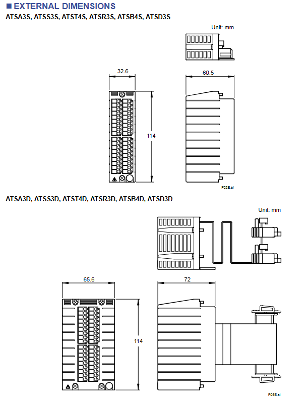
The size of the terminal block is directly related to the redundancy design, and all models within the same series have identical dimensions for standardized installation layout. The specific specifications are as follows:
Series types include model size parameters (unit: mm), reference drawings, installation and adaptation scenarios
Single channel series ATSA3S, ATSS3S, ATST4S, ATSR3S, ATSB4S, ATSD3S length x width x height: 32.6 x 60.5 x 114 F02E.ai is suitable for control cabinet layouts with limited installation space and no need for redundant design, and can be densely arranged
The dual redundant series ATSA3D, ATSS3D, ATST4D, ATSR3D, ATSB4D, ATSD3D length x width x height: 65.6 x 72 x 114 F05E.ai is suitable for the layout of control cabinets in critical control areas and requires a certain amount of installation space to ensure the heat dissipation and maintenance convenience of redundant components
(2) Dimensional design features
Height uniformity: All models have a height of 114mm, which facilitates the planning of installation positions according to the floor height inside the standard control cabinet and improves the cleanliness of the installation layout
Width differentiation: The width of the dual redundant series (72mm) is greater than that of the single channel series (60.5mm), and the length (65.6mm) is greater than that of the single channel series (32.6mm), adapting to the spatial requirements of its internal redundant structure
Standardized design: The dimensions comply with industrial equipment installation specifications and can seamlessly adapt to other supporting equipment of the Yokogawa CENTUM VP system (such as I/O modules, control cabinet rails, etc.), reducing installation difficulty
Model coding rules and ordering requirements
(1) Detailed explanation of coding rules
Explanation of optional/fixed values for the meaning of coding components
The prefix (such as ATSA, ATSS, etc.) application type identification ATSA (analog input), ATSS (analog output), ATST (thermocouple/mV), ATSR (RTD/PAT), ATSB (digital input), ATSD (digital output) prefix directly corresponds to the core application functions of the terminal block, making it easy to quickly identify
Intermediate numbers (such as 3S, 3D, 4S, 4D, etc.) indicate the number of channels and redundancy types. 3S (8 channels+single channel), 3D (8 channels+double redundancy), 4S (16 channels+single channel), 4D (16 channels+double redundancy) numbers "3" correspond to 8 channels, and "4" corresponds to 16 channels; The letters "S" and "D" distinguish redundant types
Suffix code configuration identifier -0 (fixed value) All models use a unified suffix code, with no additional optional configurations, simplifying the selection and ordering process
(2) Ordering requirements
Users need to specify the complete model (including suffix code) when placing an order, for example:
Conventional simulation input scenario: Order "ATSA3S-0"
Key scenario digital output: Order "ATSD3D-0"
Due to the fixed suffix code of -0, the core needs to confirm the model body composed of the prefix and the middle digit to ensure a complete match with the actual application type, channel number, and redundancy requirements.
- YOKOGAWA
- Reliance
- ADVANCED
- SEW
- ProSoft
- WATLOW
- Kongsberg
- FANUC
- VSD
- DCS
- PLC
- man-machine
- Covid-19
- Energy and Gender
- Energy Access
- Renewable Integration
- Energy Subsidies
- Energy and Water
- Net zero emission
- Energy Security
- Critical Minerals
- A-B
- petroleum
- Mine scale
- Sewage treatment
- cement
- architecture
- Industrial information
- New energy
- Automobile market
- electricity
- Construction site
- HIMA
- ABB
- Rockwell
- Schneider Modicon
- Siemens
- xYCOM
- Yaskawa
- Woodward
- BOSCH Rexroth
- MOOG
- General Electric
- American NI
- Rolls-Royce
- CTI
- Honeywell
- EMERSON
- MAN
- GE
- TRICONEX
- Control Wave
- ALSTOM
- AMAT
- STUDER
- KONGSBERG
- MOTOROLA
- DANAHER MOTION
- Bentley
- Galil
- EATON
- MOLEX
- Triconex
- DEIF
- B&W
- ZYGO
- Aerotech
- DANFOSS
- KOLLMORGEN
- Beijer
- Endress+Hauser
- schneider
- Foxboro
- KB
- REXROTH
- YAMAHA
- Johnson
- Westinghouse
- WAGO
- TOSHIBA
- TEKTRONIX
- BENDER
- BMCM
- SMC
- HITACHI
- HIRSCHMANN
- XP POWER
- Baldor
- Meggitt
- SHINKAWA
- Other Brands
- UniOP
- KUKA
- IBA
- Beckhoff
-
ADLINK PCI-7433 - switch value acquisition card Isolated Digital Input Card
-
ADLINK PCI-9112 - 51-12252-0D20 Multi-Function Data Acquisition Card
-
ADLINK NUPRO-A301 REV:1.4 - industrial control motherboard PICMG Full-Size SBC
-
ADLINK 51-18502-0A10 - Frame Grabber Image Acquisition Interface Card
-
ADLINK PCI-7296 - 51-12009-0A50 PCB-I-E-925=6DX1 96-CH Parallel Digital I/O Board
-
ADLINK PCI-8132 GP A2 - Motion Control Card 2-Axis Servo & Stepper Controller
-
ADLINK PCI-7442 - switch quantity card data acquisition card 64-CH Isolated Card
-
ADLINK HPX-13S4 - baseboard PICMG 1.3 Passive Backplane Chassis Baseplate
-
ADLINK NuPRO-590 / NTC-567-ZM-F36 - Single Board Computer PCB-I-E-1853=9L21 Half-Size SBC
-
ADLINK PCIe-8332 - 16-axis plate Motion Control Hardware Card
-
ADLINK NuPRO-775 REV.B1 - motherboard Pentium 4 Full-Size PICMG SBC
-
ADLINK PXI-3920 - Embedded Controller 3U PXI cPCI System Intelligence Board
-
ADLINK PCI-8134 - driver card motion control card 4-Axis Controller Board
-
ADLINK HSL-DI32-M-N-011 / HSL-TB32-M-DIN - Digital Input & Base Module PLC Distributed I/O System
-
ADLINK PCI-6216V-206 / PCI-208V 009 - 16 CH 16bit analog output card
-
ADLINK NuPro-E330 - 51-41805-0A20 PCB Single Board Computer Host Board
-
ADLINK PCI-1622C - Card 8-Port RS-232/422/485 PCI Serial Communication Board
-
ADLINK PCIe-7432 - 51-18402-0A10 Carte PCIe Avec Plage D'Entrée Élevée Isolated DIO Card
-
ADLINK PCI-7250 - PCI Acquisition Card 8-CH Relay Output Isolated DI Card
-
ADLINK PCI-7230 - 32-CH Isolated Digital I/O Card
-
ADLINK PCI-8164 - PCB 4-Axis Motion Controller Card
-
ADLINK PCI-7854 - Collection card High-Speed Link Distributed Motion Controller
-
ADLINK NuPRO-935A/LV - industrial control computer motherboard Full-Size PICMG SBC
-
ADLINK IMB-M40H - motherboard IH61-AA4 1155 LGA1155 Micro-ATX Mainboard
-
ADLINK PCI-7248 - Linhua 51-12006-0A40 48-CH Parallel Digital I/O Card
-
ADLINK HPCI-14S12U - Linhua industrial computer baseboard Passive Backplane
-
ADLINK PCI-8132 Rev.A2 - 2-Axis Servo & Stepper Motion Controller Card
-
ADLINK ACL-8111 - ISA card Multi-Function DAQ Card
-
ADLINK ACL-8111 - ISA card Multi-Function Data Acquisition Board
-
ADLINK PCI-7200 REV.A3 - Digital I/O card 12MB/s High-Speed Parallel Digital I/O
-
ADLINK PCI-7296 REV.A3 - 96-CH High-Density Opto-Isolated DIO Card
-
ADLINK PCI-7434 - 64-CH Isolated Digital Output Card
-
ADLINK M-342 - atx motherboard Industrial PC Mainboard
-
ADLINK NuPRO-935ADV (A) 1.9 - CPU Board Intel Core 2 Quad CPU Q9500 2.83GHz PICMG Board
-
ADLINK NUPRO-935A/DV - motherboard dual network port 51-41802-0A10 CPU Board
-
ADLINK PCI-RTV24 - image capture card Analog Video Frame Grabber Board
-
ADLINK HPX-13S4 - device baseboard PICMG 1.3 Passive Backplane Chassis Baseplate
-
ADLINK PCI-8134A - control card 4-Axis Motion Controller Card
-
ADLINK ACL-7130 REV. B2 - industrial control capture card Isolated Digital I/O Board
-
ADLINK EBP-13E2 - Industrial Backplane Board Passive Backplane Baseboard
-
ADLINK NuPRO-935ADV (A) 1.9 - CPU Board Intel Core 2 Quad CPU Q9500 2.83GHz PICMG SBC
-
ADLINK PCI-8134A - motion control card 4-Axis Pulse-Train Controller Card
-
ADLINK PCI-9112 REV A.1 - Multi Function DA&C Board Data Acquisition Card
-
ADLINK 51-12001-0C20 - Circuit Board Multi-Function Data Acquisition Hardware
-
ADLINK PCI-7300A - 80-CH High-Speed Digital I/O Card
-
ADLINK PCI-7230 - 16-CH Isolated Digital Input Output Card
-
ADLINK DIN-814-GP - motion control module Interface Terminal Block
-
ADLINK NUPRO-A40H - 51-41807-1A20 Industrial Control Motherboard LGA1155
-
ADLINK PCI-7433 rev A2 - Isolated Digital Input Card
-
ADLINK NuPRO-780 - Pentium III 800 512 MB SBC NuPRO780 51-41309-0B2 Single Board Computer
-
ADLINK PCI-7853 / PCI-7854 - Acquisition card High-Speed Link Control Card
-
ADLINK NUPRO-852 / NUPRO-852LV - Industrial motherboard Full-Size PICMG CPU Board
-
ADLINK NuPRO-842LV/P - 51-41360-0B30 Industrial Motherboard Half-Size PICMG SBC
-
ADLINK PCI-FIW64 - 4/2 Channel IEEE1394B Image Capture Card Frame Grabber
-
ADLINK PCI-7851 Rev A1.1 - HSL system card High-Speed Link Master Controller
-
ADLINK PCI-7230 - 51-12003-0A50 card 32-CH Isolated Digital I/O Card
-
ADLINK NuPRO-841REV:1.0 - Industrial CPU Board Mainboard
-
ADLINK NuPRO-841 REV:1.0 - motherboard Industrial Control PC Mainboard
-
ADLINK PCI-8256 - 8-Axis Advanced Motion Control PCI Board
-
ADLINK PCI-6S / PCI6S - Backplane 6-Slot Passive Backplane Board
-
ADLINK PCI-7234 REV B3 - 32-CH Isolated Digital Output PCI Card
-
ADLINK PCI-8213 - HannStar MV-4 51-45003-0b4 Board
-
ADLINK PCI-7233 - 51-12004-0a20 board PCI7233 32-CH Isolated Digital Input Card
-
ADLINK PCI-7851 - 006 51-24003-0B20 High-Speed Link Master Motion Control Card
-
ADLINK PCI-7432 - 64-CH Isolated Digital I/O PCI Cards
-
ADLINK LPCI-3488 - Card Low Profile IEEE-488 GPIB Interface Card
-
ADLINK HPCI14S REV.B1 - industrial control computer base plate Passive Backplane
-
ADLINK NEON-1020 - Industrial camera Smart Camera Vision System
-
ADLINK PCI-7432 - Isolated Digital I/O PCI Card 64-CH
-
ADLINK Pcm-7250+ - 8-Ch Relay Outputs & 8-Ch Isolated DI Module PC/104
-
ADLINK CPCI-7841 - DUAL-PORT ISOLATED CAN INTERFACE CARD CompactPCI
-
ADLINK PCI-3488 / PCI-GPIB - PCI IEEE-488 GPIB Interface Card
-
ADLINK PCI-1711U - Card Multi-Function Data Acquisition Board
-
ADLINK NUPRO-A301 - REV:1.1 1.2 1.4 PICMG Full-Size Single Board Computer
-
Adlink DIN-50S-01 - PLOTECH 51-14024-0A40 50-pin Wiring Terminal Board
-
Chroma 52962 / 58183 - PXI Optical Spectrometer carrier adapter Card
-
ADLINK PCI-6208V - PCI DATA ACQUISITION & RECORDING CARD 8-CH Analog Output
-
ADLINK HSL-DI32-DB-N - Industrial Control Board Distributed Digital Input Module
-
ADLINK HSL-AO4-U - 4-CH HIGH SPEED LINK ANALOG OUTPUT MODULE Distributed I/O
-
ADLINK PCI-7396 - 0050 GP 51-12012-0B20 96-CH High-Speed Digital I/O Card
-
ADLINK NUPRO-935A/DV - 51-41802-0A10 motherboard Industrial CPU Single Board Computer
-
ADLINK PCI-9111 DG - Industrial Acquisition Card Multi-Function DAQ Card
-
ADLINK NuPRO-E315 - industrial computer motherboard Intel Atom SHB SBC
-
ADLINK NUPRO-406 REV:B1 - Industrial Control Motherboard Full-Size PICMG CPU Board
-
ADLINK NuPRO-E330 - motherboard Industrial Control System Host Board PICMG 1.3
-
ADLINK ACL-6128A 103 - 51-11002-1A4 2-CH Isolated Analog Output Card
-
XTRAMUS cPS-H325/AC - POWER SUPPLY NUSTREAMS 600 NETWORK TESTING EQUIPMENT Power Module
-
ADLINK DIN-814P-A4 - 51-14056-0A10 Terminal Block Motion Control Breakout Board
-
ADLINK TB-24P/24-01 - 24-Channel Card Terminal Breakout Board
-
ADLINK PCI-7251 - 51-12008-0A30 PCI7251 8-CH Relay Output Isolated Digital Input Card
-
ADLINK HSL-TB64-DIN REV A1 / HSL-DO32-DB-N - 2ea Board Breakout Terminal Board Distributed I/O Module
-
ADLINK NuPRO-865 REV 3.0 - industrial computer motherboard Full-Size PICMG SBC
-
ADLINK NUPRO-A40H - motherboard 51-41807-1A30 OSP H61 Industrial PC Mainboard
-
ADLINK LPCI-3488A - PCI Card 51-12801-0A30 GPIB Interface Card
-
ADLINK DIN-825-4P0 - 51-14085-0A30 Terminal Printed Circuit Board Breakout Block
-
ADLINK IMB-T10/D2550 V - MOTHER BOARD 80-PXG160-A1A01 IMB-T10-M2G-S32G Industrial Mainboard
-
ADLINK PCI-8144N - Motion Control card Stepper Motor Controller
-
ADLINK PCI-7433 - Digital acquisition card Isolated Digital Input Card
-
ADLINK PCI-9112 DG - Data Acquisition card 51-12252-0D20 Multi-Function DAQ
-
ADLINK IMB-M40H - motherboard IH61-AA4 1155 LGA1155 Micro-ATX Mainboard
-
ADLINK TB-24P/24-01 - Carte 24 voies Terminal Breakout Board Connector Module
-
ADLINK HSL-D16DO16-M-NN - Distributed Discrete Input Output I/O Module
-
ADLINK PCI-7248 - PCI CARD 51-12006-0A40 48-CH Parallel Digital I/O Board
-
ADLINK HSL-DI32-DB-N - Industrial Control Board Distributed I/O Digital Input Module
-
ADLINK PCI-7433 - Pci 7433 Isolated Digital Input Card
-
ADLINK PCI-6208V - 008 Data acquisition card 8-CH Analog Output Card
-
ADLINK IH61-AA4 - industrial motherboard LGA1155 Micro-ATX Mainboard
-
ADLINK PXI-3920 - PXI 3U cPCI Industrial Controller Embedded System CPU Board
-
ADLINK PCI-6308 - Analog Output DAQ Card Isolated Voltage Output Card
-
ADLINK PCI-7200 - data acquisition card REV.A3 High-Speed Parallel DIO Card
-
ADLINK NuPRO-E315 - Industrial Control Computer Motherboard PICMG 1.3 SHB SBC
-
ADLINK PCI-1610C - Card 4-Port Isolated RS-232 PCI Serial Communication Card
-
ADLINK PCI-1716 - Card High-Resolution Multi-Function DAQ Card
-
ADLINK MI-965 - Industrial Mini-ITX Motherboard CPU Board
-
ADLINK PCI-1610A - Card 4-Port RS-232 PCI Serial Communication Card
-
ADLINK cBP-3208/3208R - CPCI Board 3U 8-Slot CompactPCI Backplane
-
ADLINK PCI-8134A - 51-12421-0A10 4-Axis Motion Controller Card
-
ADLINK PCI-8164 - Motion Control Card 4-Axis Advanced Controller Card
-
ADLINK NUPRO-935A/DV - motherboard dual network port 51-41802-0A10 CPU Board
-
ADLINK PCI-7248 - 51-12006-0A40 acquisition card 48-CH Parallel DIO Card
-
ADLINK PCI-7443 - 51-12022-0A10 BOARD 128-CH Isolated Digital Input Card
-
ADLINK DIN-825-GP4 - Terminal Block Interface Board Breakout Module
-
ADLINK PCI-7248 - Card 48-CH Parallel Digital I/O Card
-
ADLINK NUPRO-865 REV :3.0 - industrial motherboard Intel Pentium 4 CPU Board
-
ADLINK PCI-9113A - Isolated Analog Input Data Acquisition Card
-
ADLINK HPCI-8S4 - REV.B2 Industrial Control Base Plate Passive Backplane
-
ADLINK M-342 - atx motherboard Industrial PC Mainboard
-
ADLINK PCI-RTV24 - image capture card Analog Video Frame Grabber Board

K-JIANG

Add: Jimei North Road, Jimei District, Xiamen, Fujian, China
Tell:+86-15305925923