
K-WANG


TEKTRONIX CFG 253 Function Generator
TEKTRONIX CFG 253 Function Generator
Basic and Product Positioning
The official user manual for Tektronix CFG253 function generator (model 070-8362-04) states that the core purpose of the device is to generate various standard waveforms for audio equipment testing, ultrasound equipment calibration, servo system debugging, and other scenarios. It supports flexible adjustment of amplitude, frequency, waveform symmetry, as well as internal/external sweep functions to meet different testing needs.
Core parameters and functions
1. Key Electrical Characteristics
Parameter Category Specific Indicator Remarks
Normal frequency range (Freq/1): 0.3 Hz-3 MHz (7-speed RANGE: 1/10/100 Hz, 1/10/100 KHz, 1 MHz); 10 frequency division (Freq/10): 0.03 Hz -300 KHz Frequency accuracy: ± 5% Full scale (applicable to both normal and 10 frequency division)
Waveform types: sine wave, square wave, sawtooth wave, TTL synchronization signal. TTL signal is output from SYNC OUTPUT with fixed parameters
There are two selectable main output amplitudes (VOLTS OUT button switch):
1. Pop up mode: 0-20 V ₚₚ (open circuit), 0-10 V ₚₚ (50 Ω load)
2. Press the gear: 0-2 V ₚₚ (open circuit), 0-1 V ₚₚ (50 Ω load). The amplitude is continuously adjusted by the AMPLITUDE knob
DC offset ± 10 V (open circuit), ± 5 V (50 Ω load) Pull the DC OFFSET knob to activate, and when pressed, the offset is 0
Waveform quality sine wave distortion:<1% (10 Hz-100 KHz); Square wave rise/fall time: ≤ 100 ns (50 Ω load); Sawtooth wave linearity: ≥ 99% (20 Hz-200 KHz), ≥ 97% (200 KHz -3 MHz)-
Internal frequency scanning function: rate 0.5-50 Hz (SWEEP RATE adjustment), width 1:1-100:1 (SWEEP WIDTH adjustment); External sweep frequency: VCF INPUT input 0-+10 VDC, sweep frequency range 2 times (100:1). When performing external sweep frequency, the SWEEP button needs to pop up
2. Physical parameters
Specific indicators for parameter categories
Dimensions: Width 240 mm (9.46 in), Height 64 mm (2.53 in), Depth 230 mm (9.0 in)
Weight 2.0 kg (4.4 lb)

Safe operation and initialization
1. Safety regulations (must be followed)
Grounding requirements: The equipment should be grounded through the grounding conductor of the power cord. It is forbidden to remove the grounding pin of the power cord, otherwise it may cause electric shock; Before connecting the signal, it is necessary to confirm that the device is reliably grounded.
Line voltage and fuse:
The line voltage needs to be set to the appropriate value (supporting 4 levels: 90-110/108-132/198-242/216-250 VAC, 50-60 Hz). Setting it incorrectly can burn out the equipment;
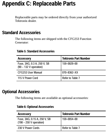
Fuses need to be matched according to voltage: 0.3 A, 250 V, 3AG specifications (part number 159-0029-00) are used for 90-132 V operation, and 0.15 A, 250 V, 3AG specifications (part number 159-0054-00) are used for 198-250 V operation. Before replacement, the power must be turned off and the signal input disconnected.
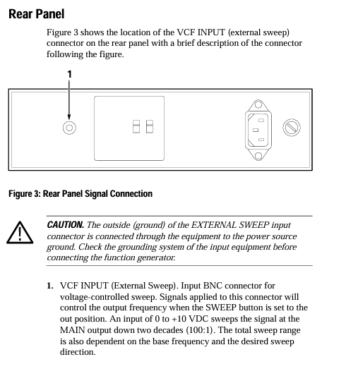
Interface limitation: The VCF INPUT input voltage of the rear panel can reach a maximum of ± 10 V ₚₖ. Exceeding this range may damage the internal circuit.
Environmental taboos: Do not operate in damp or explosive environments; Do not operate with the cover open (as it may come into contact with high-voltage components, causing electric shock or fire).
2. Initialization operation steps
Set line voltage: Adjust the equipment line voltage selector (position shown in Figure 1) according to the local power supply voltage to ensure it matches the power supply voltage.
Check the fuse: Open the fuse cover and confirm that the installed fuse specifications are compatible with the line voltage. If the specifications are incorrect, replace it.
Connect power supply: Use the device's designated power cord (standard configuration is 115V North American model, other regions require corresponding accessories, refer to Table 7), and plug it into a grounded power outlet.
Power on check: Press the POWER button, confirm that the POWER On Light is on, and the device enters standby mode.
Panel controls and interface functions
1. Front panel controls (Figure 2)
Control Number Control Name/Function Operation Instructions
1 POWER ON Light indicator light on → Device powered on, off → Power off or malfunction (such as blown fuse)
2 AMPLITUDE knob adjusts the amplitude of the main output signal, with the range determined by the VOLTS OUT button (0-2 V ₚₚ or 0-20 V ₚₚ)
Press the 3 DC OFFSET knob → DC offset is 0; Pull on → Adjust the DC level of the main output signal (range ± 10 V open circuit)
The SYMMETRY knob only takes effect when the SYMMETRY button is pressed: adjust the square wave duty cycle, sawtooth wave/sine wave rise and fall time
5 RANGE (Hz) button (7 levels: 1/10/100 Hz, 1/10/100 KHz, 1 MHz) to select the frequency range, such as pressing "1 K" → frequency range 0.3 KHz -3.0 KHz
Press the corresponding button (sine wave/square wave/sawtooth wave) to select the desired waveform for the main output
Within the selected range of the RANGE button, continuously fine tune the output frequency with the 7 FREQUEncy knob
The 8 SWEEP WIDTH knob only takes effect when the SWEEP button is pressed internally: adjust the sweep amplitude (1:1-100:1)
The 9 SWEEP RATE knob only works when scanning internally: adjust the scanning rate (0.5-50 Hz)
Press the 10 SWEEP button → Enable internal sweep frequency; Pop up → Enable external sweep (controlled through VCF INPUT)
Press the SYMMETRY button → Output frequency ÷ 10, and activate the SYMMETRY knob function at the same time; Pop up → Normal frequency, knob failure
Press the 12 VOLTS OUT button → amplitude range 0-2 V ₚₚ (50 Ω load 0-1 V ₚₚ); Pop up → amplitude range 0-20 V ₚₚ (50 Ω load 0-10 V ₚₚ)
13 SYNC (TTL) OUTPUT (BNC interface) outputs TTL synchronization signal with fixed amplitude and DC offset (not affected by AMPLITUDE/DC OFFSET knob)
14 MAIN OUTPUT (BNC interface) outputs sine wave/square wave/sawtooth wave signals, with parameters adjusted by corresponding controls
Press the POWER button to turn on the device; Press again → Shut down
2. Rear panel interface (Figure 3)
Interface Name Function Description
VCF INPUT (BNC) external sweep frequency input interface: Input 0-+10 VDC signal, control the main output frequency sweep (range of 2 times ten)
Core Function Operation Guide
1. TTL signal generation
The TTL signal parameters (amplitude, DC offset) comply with the TTL standard and cannot be adjusted. The operation steps are as follows:
Connect the oscilloscope input to the SYNC (TTL) OUTPUT interface of CFG 253 using a BNC cable;
Press the POWER button to turn on the device, use the RANGE button to select the frequency range, and rotate the FREQUEncy knob to fine tune the frequency;
Observe oscilloscope waveform: Rotate the DC OFFSET or AMPLITUDE knob, and the waveform remains unchanged (TTL signal parameters are fixed).
2. External frequency scanning operation
External frequency scanning requires controlling the scanning parameters through an external voltage source. The steps are as follows:
Connect the MAIN OUTPUT of CFG253 to the oscilloscope input using a BNC cable, and connect the external voltage source to the VCF INPUT (rear panel) of CFG253 using a BNC cable;
Rotate the SWITCHY knob to the "0.3" position (ensuring that the sweep range covers the required area);
Pop up SWEEP button (turn off internal sweep and enable external control);
Adjust the output of the external voltage source (0-+10 VDC), and observe the frequency change of the main output with an oscilloscope: voltage increase → frequency decrease, voltage decrease → frequency increase, with a sweep frequency range of 2 harmonics (100:1).
3. Adjustment of waveform symmetry
Symmetry adjustment can change the "asymmetry degree" of the waveform, which only takes effect when the SYMMETRY button is pressed. The steps are as follows:
Press the Function button to select the target waveform (square wave/sawtooth wave/sine wave);
Press the SYMMETRY button (at this point, the output frequency will automatically ÷ 10, such as the original 100 Hz → 10 Hz);
Rotate the SYMMETRY knob:
Square wave: clockwise → duty cycle increases (high-level time prolongs), counterclockwise → duty cycle decreases (low-level time prolongs), center position → duty cycle 50%;
Sawtooth wave: clockwise → increase rise time, decrease time, counterclockwise opposite;
Sine wave: clockwise → positive half cycle time prolongs, negative half cycle shortens, counterclockwise is the opposite.
Maintenance and Accessories
1. Daily maintenance
Cleaning:
After the power is cut off, use a soft cloth dipped in a mixture of "mild detergent+water" to wipe the surface of the equipment;
It is prohibited to directly spray cleaning agents onto the equipment (which may seep into the interior and damage the circuit);
Do not use solvents or abrasives containing benzene, toluene, acetone, or xylene (which can corrode the casing/scratch the panel).
Transport packaging:
If there is no original packaging, choose corrugated cardboard boxes with internal dimensions at least 3 inches larger than the equipment;
Put the equipment into a plastic bag (to prevent moisture and loose fillers from entering);
Fix the equipment with foam, bubble film and other materials to avoid shaking during transportation;
Seal the cardboard box with packing tape to ensure firmness.
Troubleshooting:
Problem: After pressing the POWER button, the POWER On Light does not light up;
Troubleshooting: After power failure, disconnect all signal cables, open the fuse cover to check if the fuse is blown. If it is blown, replace it with a new fuse of the corresponding specification (refer to the fuse specifications in the "Safety Regulations").
2. Accessories List
(1) Standard accessories (shipped with equipment)
Accessory Name Tektronix Part Number Applicable Scenarios
3AG fuse (0.3 A, 250 V) 159-0029-00 90-132 VAC power environment
115 V power cord reference table 7 North American 115 V power supply
CFG 253 User Manual 070-8362-XX Equipment Operation and Maintenance Guide
(2) Optional accessories (additional order required)
Accessory Name Tektronix Part Number Applicable Scenarios
3AG fuse (0.15 A, 250 V) 159-0054-00 198-250 VAC power environment
230 V power cord (regional adaptation) reference table 7: Europe, UK, Australia and other 230 V regions
(3) Regional compatible power cord specifications (Table 7)
Plug type applicable region Tektronix part number
North American standard plug North American (115 V) 161-0104-00
European standard plug Europe (230 V) 161-0104-06
British Standard Plug UK (230 V) 161-0104-07
Australian Standard Plug Australia (230 V) 161-0104-05
North American 230 V plug North American (230 V) 161-0104-08
Swiss standard plug Switzerland (230 V) 161-0167-00
- YOKOGAWA
- Reliance
- ADVANCED
- SEW
- ProSoft
- WATLOW
- Kongsberg
- FANUC
- VSD
- DCS
- PLC
- man-machine
- Covid-19
- Energy and Gender
- Energy Access
- Renewable Integration
- Energy Subsidies
- Energy and Water
- Net zero emission
- Energy Security
- Critical Minerals
- A-B
- petroleum
- Mine scale
- Sewage treatment
- cement
- architecture
- Industrial information
- New energy
- Automobile market
- electricity
- Construction site
- HIMA
- ABB
- Rockwell
- Schneider Modicon
- Siemens
- xYCOM
- Yaskawa
- Woodward
- BOSCH Rexroth
- MOOG
- General Electric
- American NI
- Rolls-Royce
- CTI
- Honeywell
- EMERSON
- MAN
- GE
- TRICONEX
- Control Wave
- ALSTOM
- AMAT
- STUDER
- KONGSBERG
- MOTOROLA
- DANAHER MOTION
- Bentley
- Galil
- EATON
- MOLEX
- Triconex
- DEIF
- B&W
- ZYGO
- Aerotech
- DANFOSS
- KOLLMORGEN
- Beijer
- Endress+Hauser
- schneider
- Foxboro
- KB
- REXROTH
- YAMAHA
- Johnson
- Westinghouse
- WAGO
- TOSHIBA
- TEKTRONIX
- BENDER
- BMCM
- SMC
- HITACHI
- HIRSCHMANN
- XP POWER
- Baldor
- Meggitt
- SHINKAWA
- Other Brands
- UniOP
- KUKA
- IBA
- Beckhoff
-
ADLINK CPCI-6860A - 51-31310-OB10 industrial motherboard CompactPCI SBC
-
ADLINK AmITX-SL-G-H110 - 51-7A104-0A30 Mini-ITX Industrial Motherboard
-
ADLINK PXI-2005-003 - CPCI Industrial PC Data Acquisition Card Multi-Function DAQ
-
ADLINK DININ-814M - 51-14032-0A3D SCSI-100P cable connection Interface Terminal Board
-
ADLINK CPCI-3920NA/C2D15/M1G - 3U CompactPCI Intel Core 2 Duo Single Board Computer
-
ADLINK PCIE-8560 - 51-18014-0A20 Communication Card High Speed DAQ
-
ADLINK PCI-C154+ - Motion Control Card 4-axis Motion Controller Board
-
ADLINK PCI-RTV24 - image capture card Analog Video Frame Grabber
-
ADLINK NuPRO-842LV/P - 51-41360-0B30 Industrial Motherboard CPU Board
-
ADLINK cBP-3208/3208R - CPCI Board 3U 8-Slot CompactPCI Backplane
-
ADLINK PCI-8164 - 4-Axis Motion Controller PCI Card 51-12406-0A40
-
ADLINK PCIe-GIE64+ - 4-CH GigE Vision PoE+ Frame Grabber Video Capture Card
-
ADLINK CPCI-6860 / 6860A - CompactPCI Dual Xeon Single Board Computer
-
ADLINK IEC-915GV - REV 1.1 Industrial motherboard CPU Board
-
ADLINK ND-6520 - Technology RS-232 to RS-422RS-485 Converter NuDAM Module
-
ADLINK RTV-24 / PCI-MP4S - 51-12519-1C30 4-Channel Real Time Video Capture Board
-
ADLINK cPCI-6910 / cPCI-6910AM/M1G - cPCI-6910AM/DXL16/M1G/S80G(G)-3120 BOARD CompactPCI SBC
-
ADLINK NUPRO-A40H - Linghua 51-41807-1A30 Industrial Control Computer Motherboard
-
ADLINK USB-3488A - USB to GPIB INTERFACE USB-3488A(G) Controller Module
-
ADLINK PCI-8134A - motion control card 4-Axis Controller Card
-
ADLINK PCI-7432 - Board 32-Channel input / 32-output Isolated Digital I/O PCI Card
-
ADLINK PCI-8134A - 51-12421-0A10 motion controller card tested
-
ADLINK LPCIe-7230 - 32 CH Isolated Input/output Card 2 Interrupts Low Profile PCIe
-
ADLINK NuPRO-E340 - industrial computer motherboard 51-47807-0A30 PICMG 1.3 SHB
-
ADLINK PCI-7434 - High-speed Digital Acquisition Card 64-CH Isolated DO Card
-
ADLINK NuPRO-E330 - 51-41805-0A20 Indsutrial Board SHB Single Board Computer
-
ADLINK PCI-7248 - OPTO-22 48 CHANNEL DIO DIGITAL TTL/DTL I/O 51-12006-0A40 GP
-
ADLINK PCI-8134 - Motion control card 4-Axis Controller Card
-
ADLINK AMP-208C - Movimiento Control Tarjeta 51-12420-1A20 W/Expansión & Breakout
-
ADLINK PCI-8164 - 51-12406-0A40 PCB Board 4-Axis Motion Controller Card
-
ADLINK DIN-68Y-SGII / DIN-68M-J3A - Terminal Board Connector Interface Block
-
ADLINK PCIe-7432 - Technology 51-18402-0A10 PCIe Card With High Input Range
-
ADLINK PCI-8144 / PCI-8144N - Motion control card 4-Axis Stepper Controller Card
-
ADLINK HSL-HUB3/REPEATER - HIGH SPEED LINK EXTENSION MODULES Distributed Hub Module
-
ADLINK ND-6017 - Data Logging + Acquisition 8CH A/D input Mod NuDAM Module
-
ADLINK LPCIe-7250 - data acquisition card Low Profile 8-CH Relay Output Card
-
ADLINK PCI-7432 - I/O card 64-CH Isolated Digital Input Output PCI Card
-
ADLINK IMB-M43H - industrial control computer motherboard Q87 Chip Micro-ATX
-
ADLINK MP-C154 - Motion control Card 4-Axis Motion Controller Board
-
ADLINK PCI-RTV24 - image capture card Video Frame Grabber Card
-
ADLINK PCI-7250 - 8-CH Relay Output & 8-CH Isolated DI Card
-
ADLINK PCI-6308V - 8-CH 12-Bit Isolated Analog Output PCI Card PCB-I-E-1148=6EX2
-
ADLINK PCI-7248 - capture card 48-CH Opto-22 Compatible DIO Card
-
ADLINK HSL-AI16A02-M-VV - Analog Input Output Distributed Module
-
ADLINK NuPRO-A301 - Rev:1.4 NUPRO-A301 PICMG Full-Size Single Board Computer
-
ADLINK PCI-6208V-GL - 8-CH Voltage Analog Output PCI Card
-
ADLINK PCI-8134A - 51-12421-0A10 4-Axis Motion Controller Card
-
ADLINK MNET-S23 - TECHNOLOGY MNET S23 - SERVO DRIVER CONTROL MODULE
-
ADLINK M-342 - ATX I3 I5 I7 Q67 Industrial Motherboard
-
ADLINK NUPRO-780 - Industrial Motherboard CPU Board PICMG SBC
-
ADLINK MP-C154 / MP-C152 - 4-Axis Motion Control Card Pulse-Train Controller
-
ADLINK NuPRO-935A/LV10B0 - Motherboard 51-41802-0A10 GP w/RAM Industrial Control Board
-
ADLINK MP-C154 - Motion control card 4-Axis Motion Controller Mainboard
-
ADLINK PCI-7250 - PCI Acquisition Card 8-CH Relay Output Isolated DI Card
-
ADLINK ACL-7124 - Technology Inc.24 DIO Card Digital Input Output Card
-
ADLINK PCI-8554 A2 - Timer/Counter Data Acquisition Card
-
ADLINK DIN-825-GP4 - Terminal Block Interface Board Breakout Module
-
ADLINK NuPR0-761 - REV:1.1 Industrial motherboard Full-Size PICMG SBC
-
ADLINK MXE-1401/M8G (G) - Matrix Fanless Embedded Computer Industrial PC
-
ADLINK HSL-DI16DO16-UD-NN - Digital 16 Channel I/O Mod Distributed I/O Module
-
ADLINK ND6520 - NUDAM INTELLIGENT DA&C MODULE RS232-RS-422/RS485 CONVERTOR
-
ADLINK NUPRO-761 - REV:1.1 Industrial Motherboard CPU Board
-
ADLINK AMP-208C - Motion Control Card 51-12420-1A20 DSP-based 8-axis
-
ADLINK NuPRO-A301REV 1.4 - with packaging industrial computer motherboard PICMG SBC
-
ADLINK PCM-9112+ - 51-12300-0A2 industrial motherboard Multi-Function DAQ PC/104 Module
-
ADLINK PCM-7250+ - 8-CH Relay Outputs & 8-CH Isolated DI Module PC/104
-
ADLINK PCI-RTV24 - Image capture card Analog Video Frame Grabber
-
ADLINK PCI-8134 - Motion Controller PCI Card 4-Axis Controller Board
-
ADLINK PCI-7432 - Isolated Digital I/O PCI Card
-
ADLINK PCI-8554 A2 - acquisition card Timer/Counter Card
-
ADLINK PCI-8132 - Rev.A2 2-Axis Servo & Stepper Motion Controller Card
-
ADLINK PCI-8132 - Data Acquisition card 2-Axis Motion Controller Card
-
ADLINK EBP-13E4 - 51-46703-0A30 Industrial Backplane Board Passive Backplane
-
ADLINK PCI-800L - Electronic Card Interface Controller Card
-
ADLINK PCIe-GIE72 - 51-18531-0A10 PCB Board GigE Vision Frame Grabber
-
ADLINK DAQ-2010(G)-OOBO - Simultaneous-Sampling Multi-Function DAQ Card
-
ADLINK PCI-9112 - REV.B1 Multifunction DAQ Card Data Acquisition Card
-
ADLINK PCI-7230 - 51-12003-DA60 32-CH Isolated Digital I/O Card
-
ADLINK PCI-7432 - Data Acquisition Card Isolated Digital I/O PCI Card
-
ADLINK ETX-AT-N270-18/LXE - 51-71111-0A20 ETX CPU Module Motherboard
-
ADLINK HSL-DI32-UD-N - DIGITAL INPUT 32 POINTS MODULE Distributed I/O
-
ADLINK AMP-204C - Motion Control card DSP-Based 4-Axis Advanced Controller
-
ADLINK MNET-4XMOG-0050 - Four-axis Motion Controller Distributed Motion Module
-
ADLINK AMP-204C - Motion control card DSP-Based 4-Axis Pulse-Train Controller
-
ADLINK PCI-7442 - Switch card 64-Channel Datalogging & Acquisition Card
-
ADLINK M-302 - Industrial control motherboard ATX PC Board
-
ADLINK NUPRO-852 / NUPRO-852LV - Industrial motherboard Single Board Computer
-
ADLINK PCI-8134 - REV.B1. 4-Axis Motion Controller Card
-
ADLINK PCI-GIE62 + - 51-18502-0A20 2-CH GigE Vision Frame Grabber PoE Card
-
ADLINK PCI-MPG24 - 51-12523-0B20 MPEG4 Card Video Compression Hardware
-
ADLINK HSL-TB32-M-DIN - 32-CH I/O TERMINAL W/ HSL-AI16AO2-M-VV MODULE
-
ADLINK PCI-M114-GL - PCB Ver 2.1 Motion Controller Axis Card
-
ADLINK IMB-M40H - SYM76996H61 motherboard Industrial Computer Mainboard
-
ADLINK NUPRO-A40H - 51-41807-1A20 industrial control motherboard H61 Chip
-
ADLINK PCI-M114-GL - Axis Card Data Acquisition Card PCB VER2.2 Motion Controller
-
ADLINK PCI-8134 - Motion Controller PCI Card 4-Axis Controller Board
-
ADLINK PCI-8102 - Motion control card 2-Axis Servo & Stepper Controller
-
ADLINK NuPRO-841REV:3.0 - motherboard Industrial Control PC Board
-
ADLINK HSL-TB32-U-DIN REV A1 - Breakout Terminal Board Field I/O Module
-
ADLINK AMP-204C - Motion Control card DSP-Based 4-Axis Pulse-Train Controller
-
ADLINK NUPRO-A40H - 51-41807-1A20 industrial control motherboard H61 PC Board
-
ADLINK PCI-6308A / PCI-6308V - 51-12202-0A50 Isolated Analog Output Card
-
ADLINK AMP-204C - DSP-Based 4-Axis Advanced Pulse-Train Motion Controller
-
ADLINK PCI-7434 - Technology 64-Channel Isolated Digital I/O PCI Cards
-
ADLINK CPCI-6840 / CPCI-6840V / PM16/M1G-12G0 - CompactPCI Single Board Computer CPU Module
-
ADLINK PCIE-GIE74 - Motherboard Video Capture Card 51-18531-0A10 Frame Grabber
-
ADLINK NuPRO-E330 - industrial computer equipment motherboard Control Mainboard
-
ADLINK AMP-208C / 51-12420-1A20 - Motion Control Card W/ Expansion & Breakout Board
-
ADLINK HPCI-14S12U - industrial computer baseboard Passive Backplane 14 Slots
-
ADLINK PCI-8164 - 4-Axis Motion Controller PCI Card W/ 1x Cable, 1x Breakout Box
-
ADLINK PCIe-RTV24 - 51-18016-0A20 Image Acquisition Video Capture Card
-
ADLINK M-342 - 5 PCI ATX Motherboard Industrial PC Mainboard
-
ADLINK PCI-FIW64 - 4/2 Channel IEEE1394B Image Capture Card FireWire Frame Grabber
-
ADLINK PCI-7432 - digital IO card 64-CH Isolated Digital Input Output Card
-
ADLINK 51-12001-0C20 - Circuit Board PCI-7200 Data Acquisition Controller Card
-
ADLINK PXI-3920 - PXI 3U cPCI Industrial Controller Embedded System CPU Board
-
ADLINK NuPRO-841REV:2.0 - motherboard Industrial Control PC Board
-
ADLINK NuPro-E330 - 51-41805-0A20 PCB Industrial Control Computer Motherboard
-
ADLINK PCI-RTV24 - Image capture card Analog Video Frame Grabber
-
ADLINK PCI-7442 - Switch card 64-Channel Datalogging & Acquisition Card
-
ADLINK HPX-13S4 - device baseboard Passive Backplane Riser Card
-
ADLINK PCI-9112 REV A.1 - Multi Function DA&C Board Data Acquisition Card
-
ADLINK PCI-7248 - 51-12006-0A40 Card Control 48-CH Digital I/O Module
-
ADLINK CPCI-6860 / 6860A - motherboard CompactPCI Dual Xeon Single Board Computer
-
ADLINK DPAC-3020-11(G) - Embedded PC Automation Controller Machine Control Board
-
ADLINK NuPRO-841 REV:1.0 - industrial control motherboard CPU Board
-
ADLINK MNET-4XMOG-0050 - Four-axis Motion Controller MNET Motion Control Card
-
ADLINK ETX-AT-N270-18/LXE - 51-71111-0A20 ETX CPU Module Motherboard

K-JIANG

Add: Jimei North Road, Jimei District, Xiamen, Fujian, China
Tell:+86-15305925923