
K-WANG


Watlow CLS200 series controller
Watlow CLS200 series controller
Product Overview and Core Features
1. Product positioning and circuit configuration
The CLS200 series controller is an industrial grade multi loop control device that provides 4 (CLS204), 8 (CLS208), or 16 (CLS216) completely independent control loops. It can be used as an independent controller (operated through a 2-line 16 character display screen and touch keyboard) or as a core component of a computer monitoring data acquisition and control system, supporting local or remote control through EIA/TIA-232 or EIA/TIA-485 serial communication interfaces.
2. Core functional features
Multi type sensor compatibility: directly connect multiple thermocouples (J, K, T, S, R, B, E types) without hardware modification, with reference compensation, linearization, measurement offset calibration, disconnection/short circuit/reverse connection detection functions, supporting Fahrenheit/Celsius display; Support 3-wire 100 Ω platinum resistance RTD (0.00385 curve), calibration resistors need to be configured for CLS204/CLS208; Automatic calibration of linear analog input (requires installation of calibration resistors), input two points to automatically calibrate according to user units.
Flexible output control: Each circuit includes dual outputs for heating and cooling, with independent configuration of output parameters; Supports multiple control and output modes, with control outputs set to ON/OFF, TP, DZC, and SDAC modes. Each circuit can have up to 2 outputs set to ON/OFF, P, PI, or PID control, and supports reverse/forward actions.
Alarm and Monitoring: Supports high/low process alarm and high/low deviation alarm. Each loop alarm can independently activate digital output or group activate output; The global alarm output is activated upon any alarm trigger and needs to be manually confirmed before being turned off; The CPU watchdog timer output can monitor system faults, keep the relay closed during controller operation, and trigger notifications when the microprocessor shuts down.
Communication and Storage: Supports Modbus RTU protocol, connects PLC, operation interface terminal, and third-party software through EIA/TIA-232/485 interface; The memory can store up to 8 tasks, which can be called locally or remotely through numerical input. Each task includes operating conditions such as set values and alarms.
Other practical functions: support non-linear output curve selection; The self-tuning function can quickly optimize PID parameters; Pulse counter input (up to 2000Hz) can accurately control motor or belt speed; Low power shutdown function, automatically shuts down and all outputs when the input voltage is below the safe value detected 🔶 1-163, 1-164, 1-165, 1-166 🔷。
Installation Guide
1. Preparation and safety requirements before installation
Environmental requirements: The controller should be installed in a location without excessive temperature (not exceeding 50 ℃/122 ℉), low dust, and unauthorized operation, to avoid electromagnetic and radio frequency interference. Sensor wiring should be kept away from high-voltage lines, power switch equipment, and motors.
Safety warning: Cut off the power supply throughout the entire process before installation to prevent electric shock; The controller may malfunction to 0% or 100% power output state, requiring the installation of independent external safety shutdown devices (such as FM certified high/low process limit controllers and mechanical contactors), and the safety devices must be independent of the process control equipment. If the malfunction may result in death or injury, FM certified safety devices must be used.
Tool preparation: It is recommended to use a 1/8-DIN rectangular punch (such as Greenlee 600-68), curved saw and metal file (stainless steel/thick panel), nibbler and metal file (aluminum/light panel), as well as a cross screwdriver, 1/8 inch (3mm) straight screwdriver (for wiring), and multimeter.
2. Installation steps of core components
(1) Controller installation
Panel opening: A hole of 1.80 inches (46mm) x 3.63 inches (92mm) (tolerance ± 0.02 inches/1mm) needs to be opened on the panel, and the panel thickness should not exceed 0.2 inches (5mm).
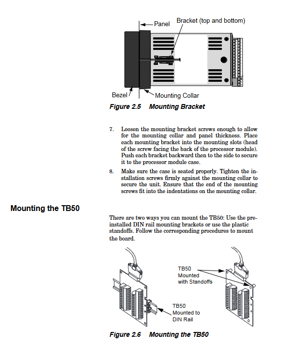
Installation process: First, remove the bracket and collar of the processor module, and slide the module into the panel cut; Insert the installation collar onto the back of the module (with the screw groove facing back), loosen the screws of the installation bracket, insert the bracket into the installation groove (with the screw head facing back), tighten and fix it laterally; Ensure that the casing is installed in place and tighten the screws to secure the bracket against the collar.
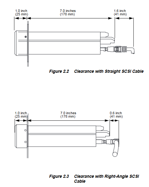
Space requirements: The controller can extend up to 7.0 inches (178mm) behind the panel, and the screw bracket can extend up and down by 0.5 inches (13mm) each; If using a straight SCSI cable, an additional 1.6 inches (41mm) should be reserved behind the terminal board; If using a right angle SCSI cable, an additional 0.6 inches (15mm) need to be reserved.
(2) Installation of TB50 terminal board
TB50 is a screw terminal interface used to connect relays, encoders, and discrete I/O devices. It supports 18 AWG (0.75mm ²) wires and is connected to the controller through a 50 pin SCSI cable. There are two installation methods:
DIN rail installation: First, clamp the hook side of TB50 onto the rail, and then push the buckle side into place for fixation; Use a Phillips screwdriver to pry open the buckle during disassembly.
Bracket installation: First remove the DIN rail bracket of TB50, mark 4 installation holes, drill the # 6 (3.5mm) screw hole, and fix TB50 with 4 screws; The four small holes on the terminal board can be used to secure wiring with zip ties.
(3) Installation of power supply and DAC module
Power installation: If using a built-in power supply, choose a Class 2, isolated and regulated 12-24V DC (1A) power supply, and install it according to the instructions of the power supply manufacturer; The installation bracket with built-in power supply needs to reserve a gap of 0.3 inches (8mm) and be fixed with 2 # 10 (5.0mm) screws. Pay attention to using 6-32 and 1/4 inch screws to avoid damaging the power supply with excessively long screws.
Installation of Dual DAC/Serial DAC Module: The module is used to convert the open collector output of the controller into an analog signal. During installation, it is necessary to select a wall position close to the controller, mark and drill 4 # 8 (4.0mm) screw holes for fixation; The output signal range of the module is configured through jumper wires. The dual DAC requires independent power supply to isolate the digital and analog circuits. The serial DAC supports cascading multiple modules (up to 16), and the 5V DC output of the CLS200 power supply is required to power multiple modules 🔶 1-381 to 1-397, 1-773 to 1-794 🔷。
3. System cabling and testing
(1) Wiring specifications
Cable selection: It is recommended to use multi strand wires (solid lines are only used for fixed scenarios and are prone to poor contact during maintenance); Thermocouple extension wire uses 20 AWG (0.5mm ²); Shielded wires are used for analog input/output and RTD input, with one end of the shielding layer connected to the ground; Except for thermocouples, copper wires are used for other connections.
Anti interference measures: Separate the wiring of high and low voltage lines to avoid parallelism or bundling; If an electromechanical relay must be used, a 0.01 μ F (1000V AC) capacitor and a 47 Ω (0.5W) resistor absorption network should be connected in series at both ends of the normally open contact of the relay load, or a metal oxide varistor (MOV) and a bidirectional voltage regulator diode (Transorb) should be connected in parallel.
Grounding requirements: Avoid grounding loops, and the DC common terminal, analog common terminal, reference voltage common terminal, communication common terminal, etc. of the controller must not be connected or grounded to each other; CLS216 is a single ended input, and all sensor negative terminals are connected to the analog common terminal. Grounded or ungrounded thermocouples must be used uniformly, and special wiring is required for mixed current and low voltage inputs.
(2) Power supply and terminal connection
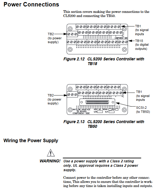
Power connection: Connect the DC common terminal of the power supply to the DC common terminal of CLS200 TB2 (-), and connect the positive terminal of the power supply to the DC positive terminal of TB2 (+); If an external power source is used to supply power to the load, the DC common terminal of the load power source must be connected to the DC common terminal of the controller power source; The grounding terminal of TB2 must be connected to the controller casing and grounded; Finally, connect the 120/240V AC power supply to the power source.
TB50 connection: Connect TB50 to the controller through a 50 pin SCSI cable, ensuring that the cable is securely inserted into the interface.
(3) System testing
TB50/TB18 test: After power on, the controller displays "SCALE CHECK SUM", followed by a bar chart; Measure the+5V DC voltage of TB50/TB18 with a multimeter (terminal 1 is positive, terminal 3/TB18 terminal 2 is common), and the voltage should be between 4.75-5.25V.
Digital output test: Connect a 500 Ω -100k Ω resistor between terminal 1 (+5V) of TB50/TB18 and the digital output terminal to be tested. Use the "MANUAL I/O TEST" menu to control the output switch. When the output is ON, the voltage is less than 1V, and when it is OFF, the voltage is 4.75-5.25V. The heating output is enabled by default and needs to be set to manual mode for 100% output before testing.
Digital input test: Disconnect the input wiring and enter the "DIGITAL INPUTS" test menu. When the input is not connected, it displays "H" (high level/open circuit). When the input terminal is connected to the controller common terminal (TB50 terminal 3/TB18 terminal 2), it displays "L" (low level/closed).
Operation Guide
1. Front panel and button functions
Panel layout: Includes a 2-line 16 character display screen and an 8-key keyboard. The display screen can display process variables, set values, output levels, and other information. The keyboard includes "Ramp/OAK" (slope/constant temperature control), "ALARM ACK" (alarm confirmation), "MAN/AUTO" (manual/automatic switching), "CHNG SP" (set value modification), "ENTER" (confirm/store), "BACK" (return/cancel), "YES" (up/add), and "NO" (down/reduce) keys.
Key function: The "YES" key is used to select menus/parameters, confirm YES/NO prompts, increase values, and stop scanning; The "NO" key is used to skip menus/parameters, reject YES/NO prompts, reduce values, stop scanning, and perform NO key reset (press and hold to restore default parameters when powered on); The 'BACK' key is used to cancel editing, return to the previous menu, and switch display modes; The 'ENTER' key is used to store modifications, enter the next parameter, and start scanning (press twice); The "CHNG SP" key is used to modify the set value; The "MAN/AUTO" key is used to switch between manual/automatic modes, adjust manual output, and start self-tuning; The 'RAMP/SOAK' key is used to allocate slope/constant temperature curves, select modes, and view curve status (controllers with this option only); The 'ALARM ACK' button is used to confirm alarms and reset global alarm outputs.
2. Core display mode
(1) Bar chart display (default upon startup)
Display content: The top displays up to 8 circuit numbers/names and alarm symbols (such as "<" for low process/deviation alarm, ">" for high process/deviation alarm, "F" for sensor failure), and the bottom displays control status symbols (such as "M" for manual, "A" for automatic, "T" for self-tuning).
Operation: Press the "YES"/"NO" keys to switch circuit groups, press "ENTER" twice to start scanning (each group displays for 3 seconds), press any key to stop scanning, press the "BACK" key to switch to task display (if enabled) or single circuit display.
(2) Single loop display
Display content: Display the process variables, engineering units, set values, control status (MAN/AUTO/TUNE/HEAT/COOL), and output percentages of a single circuit. If dual outputs are enabled, heating and cooling output percentages will also be displayed separately.
Operation: Press the "YES"/"NO" keys to switch circuits, press "ENTER" twice to start single circuit scanning (each circuit displays for 1 second), press any key to stop, press the "BACK" key to switch to task display or bar chart display.
(3) Alarm display
Trigger logic: When the process/deviation/sensor failure/system alarm is triggered, the controller automatically switches to the single loop display of the fault circuit, and the global alarm output is activated, displaying a 2-character alarm code (such as "FS" indicating thermocouple disconnection, "HP" indicating high process alarm). When the sensor fails, the output is set to the "sensor fault heating/cooling output" parameter value (default 0%), and the alarm code flashes. Other functions can only be operated after confirmation.
Alarm types: including sensor faults (thermocouple open/short/reverse, RTD open/short), process alarms (high/low process, high/low deviation), system alarms (battery failure, low power consumption, excessive ambient temperature, hardware failure), each alarm corresponds to a specific code and processing method.
Alarm confirmation: Press the "ALARM ACK" button to confirm the alarm. If multiple circuits alarm, they will switch to each faulty circuit in sequence. All alarms need to be confirmed before resetting the global alarm output.
3. Key operational procedures
(1) Modify the set value
Switch to the single circuit display of the target circuit;
Press the "CHNG SP" button, and the display screen will show "SETPOINT? XX" (XX is the current set value);
Press the "YES" key to enter modification mode, and press the "YES"/"NO" keys to increase or decrease the set value;
Press the "ENTER" key to save and return to the single circuit display, or press the "NO"/"BACK" keys to cancel the modification.
(2) Manual/automatic mode switching
Switch to the single circuit display of the target circuit;
Press the "MAN/AUTO" button, press the "YES" button to confirm the mode switch, or press the "NO" button to cancel (in automatic mode);
If switching to manual mode, press the "YES"/"NO" keys to set the heating/cooling output percentage, and press the "ENTER" key to save;
If switched to automatic mode, the controller controls according to the preset PID parameters;
If switched to TUNE mode, the controller automatically optimizes the PID parameters.
(3) Self tuning operation
Prerequisite: The controller has installed control and sensor circuits, the thermal load is in place, the system can operate safely, and the approximate target temperature is known.
Operation steps:
Switch to the single loop display of the target loop, ensuring that the process variable is stable and in manual mode;
Set the set value close to the normal operating temperature (note: during the self-tuning period, the output is 100% or the output limit value must be within a safe range);
Press the "ENTER+ALARM ACK+CHNG SP" key combination to enter the settings menu, and set "INPUT Filter" to 0 SCANS in the "SETUP LOOP INPUT" menu;
Return to single circuit display, press the "MAN/AUTO" key, press the "NO" key to switch to TUNE mode, press the "ENTER" key to start self-tuning (TUNE "flashes);
After self-tuning is completed, automatically switch to automatic mode and restore the original setting value of "INPUT Filter".
Setting guide
1. Enter the settings menu
Enter through the "three key combination": Under the single circuit display of the target circuit, press the "ENTER", "ALARM ACK", and "CHNG SP" keys in sequence (not simultaneously). If there is no operation for 3 minutes, the controller will automatically return to the single circuit display to prevent unauthorized access.
2. Core Settings Menu
(1) SETUP Global Parameters
Includes parameters such as task loading/saving, task selection digital input, output forced digital input, startup alarm delay, ramp/constant temperature time reference, keyboard lock, power on output status, process power digital input, controller address, communication parameters (baud rate, protocol, verification), AC line frequency, digital output polarity during alarm, etc. For example:
Load SETUP FROM JOB "/" SAVE SETUP TO JOB ": Load/save tasks 1-8, which include PID parameters, control status, alarm settings, etc;
Controller Address ": Set the communication address (1-247) to be unique in the EIA/TIA-485 network. Anasoft software supports up to 16 controllers (addresses 1-16);
Communications BAUD RATE ": Set the baud rate (2400/9600/19200) to be consistent with the upper computer.
(2) Loop input setting (SETUP LOOP INPUT)
Configure input type (thermocouple/RTD/linear/pulse/SKIP), circuit name, input unit, input offset, thermocouple reverse detection, pulse sampling time, display format, linear calibration parameters, input filtering, etc., for example:
INPUT TYPE ": Select the sensor type, SKIP is used for unused circuits (does not detect alarms, does not participate in scanning);
INPUT SCALING ": Linear input requires setting high/low process variables and corresponding high/low readings to achieve signal calibration;
INPUT Filter ": Set the filtering for the 0-255 scan period, disable filtering at 0, to suppress input signal fluctuations.
(3) Loop Control Parameter Setting (SETUP LOOP Control PARAMS)
Set PID core parameters such as heating/cooling ratio band (PB), integration time (TI), differentiation time (TD), control filtering, temperature difference (SPREAD), PID recovery digital input, etc., for example:
HEAT Control PB ": The larger the proportional band, the weaker the proportional effect, and the default value varies with the sensor type (e.g. J-type thermocouple defaults to 50);
SPREAD ": It is a hysteresis loop during switch control, and a switching threshold (0-255, consistent with the display format) for process variable deviation from the set value during PID control.
(4) Loop output setting (SETUP LOOP OUTPUTS)
Enable/disable heating/cooling output, set output type (TP/DZC/SDA/ON/OFF/3P DZC), cycle time (TP mode), SDAC parameters, output action (reverse/forward), output limit, sensor fault output, thermocouple break output average, output linearity, etc., for example:
HEAT CON OUTPUT ": Enable/disable heating output, which can be used as an alarm output when disabled;
SENSOR FAIL HT OUTPUT ": Heating output percentage (0-100%) in case of sensor failure, default 0%.
(5) SETUP LOOP ALARMS
Configure high/low process alarm settings, alarm types (OFF/ALARM/MOTOR), alarm outputs, deviation alarm values, alarm dead zones, alarm delays, for example:
HI PROC ALARM SETPT "/" LO PROC ALARM SETPT ": High/low process alarm threshold, within the sensor range;
ALARM DEADBAND ": Alarm hysteresis, preventing process variables from fluctuating near the alarm threshold and causing frequent alarms (0-255, units consistent with display format).
(6) Manual I/O Test
Test digital input (displaying H/L status), digital output (manually switching ON/OFF), keyboard (displaying key names by pressing any key), and display screen (displaying pixel patterns) to troubleshoot I/O faults.
Troubleshooting and Maintenance
1. Common faults and their solutions
(1) Power and display malfunction
LOW POWER: Confirm that the power supply voltage is ≥ 12.0V DC (1A), and check the power supply wiring; If the error persists after restarting, record the parameters and perform a NO key reset. If it is ineffective, contact the manufacturer.
BATTERY DEAD (battery failure): When the battery cannot maintain parameter storage during power failure, the parameters will be reset to default and the battery needs to be replaced. If it fails, contact the manufacturer.
The display screen does not light up: check the power wiring and confirm that the power supply is normal; If it is an EPROM issue, replace the EPROM (anti-static operation is required); If the controller is damaged, send it back for repair.
(2) Sensor malfunction
Thermocouple failure (FS/RT/ST): Check the thermocouple wiring (positive and negative poles, broken wires, short circuits), and confirm whether the "REVERSED T/C DETECT" parameter is enabled; If it is a broken wire, replace the thermocouple; If it is reversed, adjust the wiring.
RTD fault (RO/RS): Check the RTD wiring (open/short circuit), measure the RTD resistance (20-250 Ω normal), replace if damaged.
(3) Communication malfunction
Check whether the communication parameters (address, baud rate, protocol, verification) are consistent with the upper computer;
Check the wiring of EIA/TIA-232/485, terminal resistance (150-200 Ω) is required for EIA/TIA-485, shielded wire is needed for long-distance communication, and one end of the shielding layer is grounded;
Use a communication tester or oscilloscope to detect the signal and eliminate the grounding loop (an optical isolation converter can be used).
2. Maintenance operations
(1) NO key reset
Restore all parameters to default values. Operation: Press and hold the "NO" key after power off, release it after power on, and press the "YES" key to confirm when the prompt "RESET WITH DEFAULTS?" appears; Before resetting, the parameters need to be recorded, and the computer monitoring system can save the parameters through software.
(2) EPROM replacement
Prerequisite: A cross screwdriver, a straight screwdriver, and an anti-static wristband are required. Record the parameters before replacement.
Step: Power off, remove the 4 screws on the front panel of the controller, and take out the electronic components; Remove the 4 screws from the top circuit board and unplug the circuit board; Use an IC extractor to remove the old EPROM and insert the new EPROM (pay attention to the direction of the notch); Reverse the steps to reassemble, power on and re-enter the parameters.
(3) Calibration resistor installation
The current, voltage, and RTD inputs of CLS204/CLS208/CLS216 require the installation of specific calibration resistors. The resistance value and position vary with the input type (such as CLS204 current input using 6 Ω or 3 Ω resistors), and must be soldered by professional technicians to avoid damaging the circuit board.
Technical specifications
1. Core specifications of the controller
Environmental parameters: working temperature 0-50 ℃, storage temperature -20-60 ℃, humidity 10-95% (non condensing), indoor use.
Physical dimensions: CLS200 processor module weighs 1.98 pounds (0.9kg), measures 8.0 inches (203mm) in length (without SCSI interface), has a width of 3.78 inches (96mm), and a height of 1.96 inches (50mm); TB50 weighs 0.32 pounds (0.15kg), measures 4.1 inches (104mm) in length, 4.0 inches (102mm) in width, and 1.5 inches (37mm) in height 🔶 1-3423, 1-3425, 1-3451 🔷。
Input/output: Analog input supports -10 to+60mV (or 0-25V with calibrated resistor), resolution>14 bits, accuracy 0.03% of full range (25 ℃); 8 digital inputs (TTL level), 35 digital outputs (open collector, maximum 60mA/24V DC); One CPU watchdog output (maximum 10mA/5V DC).
Communication: Supports EIA/TIA-232 (3-wire, maximum 50 feet), EIA/TIA-485 (4-wire, maximum 4000 feet), baud rate 2400/9600/19200, protocol Modbus RTU/Anafaze/Allen Bradley, verification BCC/CRC.
2. Auxiliary component specifications
Power supply: Input 120/240V AC (0.75A, 50/60Hz), output 5V DC (4A), 15V DC (1.2A).
Dual DAC: Operating temperature 0-50 ℃, output supports 4-20mA, 0-5V, 0-10V, accuracy ± 0.75% of full scale, load resistance varies with output type and power supply.
Serial DAC: Operating temperature 0-70 ℃, output supports 0-10V or 4-20mA (jumper selection), can cascade up to 16, CE certified.
- YOKOGAWA
- Reliance
- ADVANCED
- SEW
- ProSoft
- WATLOW
- Kongsberg
- FANUC
- VSD
- DCS
- PLC
- man-machine
- Covid-19
- Energy and Gender
- Energy Access
- Renewable Integration
- Energy Subsidies
- Energy and Water
- Net zero emission
- Energy Security
- Critical Minerals
- A-B
- petroleum
- Mine scale
- Sewage treatment
- cement
- architecture
- Industrial information
- New energy
- Automobile market
- electricity
- Construction site
- HIMA
- ABB
- Rockwell
- Schneider Modicon
- Siemens
- xYCOM
- Yaskawa
- Woodward
- BOSCH Rexroth
- MOOG
- General Electric
- American NI
- Rolls-Royce
- CTI
- Honeywell
- EMERSON
- MAN
- GE
- TRICONEX
- Control Wave
- ALSTOM
- AMAT
- STUDER
- KONGSBERG
- MOTOROLA
- DANAHER MOTION
- Bentley
- Galil
- EATON
- MOLEX
- Triconex
- DEIF
- B&W
- ZYGO
- Aerotech
- DANFOSS
- KOLLMORGEN
- Beijer
- Endress+Hauser
- schneider
- Foxboro
- KB
- REXROTH
- YAMAHA
- Johnson
- Westinghouse
- WAGO
- TOSHIBA
- TEKTRONIX
- BENDER
- BMCM
- SMC
- HITACHI
- HIRSCHMANN
- XP POWER
- Baldor
- Meggitt
- SHINKAWA
- Other Brands
- UniOP
- KUKA
- IBA
- Beckhoff
-
Basler Electric DECS-250-CN1SN1N Automatic Voltage Regulator for Generator Excitation Control
-
ADLINK CPCI-6860A - 51-31310-OB10 industrial motherboard CompactPCI SBC
-
ADLINK AmITX-SL-G-H110 - 51-7A104-0A30 Mini-ITX Industrial Motherboard
-
ADLINK PXI-2005-003 - CPCI Industrial PC Data Acquisition Card Multi-Function DAQ
-
ADLINK DININ-814M - 51-14032-0A3D SCSI-100P cable connection Interface Terminal Board
-
ADLINK CPCI-3920NA/C2D15/M1G - 3U CompactPCI Intel Core 2 Duo Single Board Computer
-
ADLINK PCIE-8560 - 51-18014-0A20 Communication Card High Speed DAQ
-
ADLINK PCI-C154+ - Motion Control Card 4-axis Motion Controller Board
-
ADLINK PCI-RTV24 - image capture card Analog Video Frame Grabber
-
ADLINK NuPRO-842LV/P - 51-41360-0B30 Industrial Motherboard CPU Board
-
ADLINK cBP-3208/3208R - CPCI Board 3U 8-Slot CompactPCI Backplane
-
ADLINK PCI-8164 - 4-Axis Motion Controller PCI Card 51-12406-0A40
-
ADLINK PCIe-GIE64+ - 4-CH GigE Vision PoE+ Frame Grabber Video Capture Card
-
ADLINK CPCI-6860 / 6860A - CompactPCI Dual Xeon Single Board Computer
-
ADLINK IEC-915GV - REV 1.1 Industrial motherboard CPU Board
-
ADLINK ND-6520 - Technology RS-232 to RS-422RS-485 Converter NuDAM Module
-
ADLINK RTV-24 / PCI-MP4S - 51-12519-1C30 4-Channel Real Time Video Capture Board
-
ADLINK cPCI-6910 / cPCI-6910AM/M1G - cPCI-6910AM/DXL16/M1G/S80G(G)-3120 BOARD CompactPCI SBC
-
ADLINK NUPRO-A40H - Linghua 51-41807-1A30 Industrial Control Computer Motherboard
-
ADLINK USB-3488A - USB to GPIB INTERFACE USB-3488A(G) Controller Module
-
ADLINK PCI-8134A - motion control card 4-Axis Controller Card
-
ADLINK PCI-7432 - Board 32-Channel input / 32-output Isolated Digital I/O PCI Card
-
ADLINK PCI-8134A - 51-12421-0A10 motion controller card tested
-
ADLINK LPCIe-7230 - 32 CH Isolated Input/output Card 2 Interrupts Low Profile PCIe
-
ADLINK NuPRO-E340 - industrial computer motherboard 51-47807-0A30 PICMG 1.3 SHB
-
ADLINK PCI-7434 - High-speed Digital Acquisition Card 64-CH Isolated DO Card
-
ADLINK NuPRO-E330 - 51-41805-0A20 Indsutrial Board SHB Single Board Computer
-
ADLINK PCI-7248 - OPTO-22 48 CHANNEL DIO DIGITAL TTL/DTL I/O 51-12006-0A40 GP
-
ADLINK PCI-8134 - Motion control card 4-Axis Controller Card
-
ADLINK AMP-208C - Movimiento Control Tarjeta 51-12420-1A20 W/Expansión & Breakout
-
ADLINK PCI-8164 - 51-12406-0A40 PCB Board 4-Axis Motion Controller Card
-
ADLINK DIN-68Y-SGII / DIN-68M-J3A - Terminal Board Connector Interface Block
-
ADLINK PCIe-7432 - Technology 51-18402-0A10 PCIe Card With High Input Range
-
ADLINK PCI-8144 / PCI-8144N - Motion control card 4-Axis Stepper Controller Card
-
ADLINK HSL-HUB3/REPEATER - HIGH SPEED LINK EXTENSION MODULES Distributed Hub Module
-
ADLINK ND-6017 - Data Logging + Acquisition 8CH A/D input Mod NuDAM Module
-
ADLINK LPCIe-7250 - data acquisition card Low Profile 8-CH Relay Output Card
-
ADLINK PCI-7432 - I/O card 64-CH Isolated Digital Input Output PCI Card
-
ADLINK IMB-M43H - industrial control computer motherboard Q87 Chip Micro-ATX
-
ADLINK MP-C154 - Motion control Card 4-Axis Motion Controller Board
-
ADLINK PCI-RTV24 - image capture card Video Frame Grabber Card
-
ADLINK PCI-7250 - 8-CH Relay Output & 8-CH Isolated DI Card
-
ADLINK PCI-6308V - 8-CH 12-Bit Isolated Analog Output PCI Card PCB-I-E-1148=6EX2
-
ADLINK PCI-7248 - capture card 48-CH Opto-22 Compatible DIO Card
-
ADLINK HSL-AI16A02-M-VV - Analog Input Output Distributed Module
-
ADLINK NuPRO-A301 - Rev:1.4 NUPRO-A301 PICMG Full-Size Single Board Computer
-
ADLINK PCI-6208V-GL - 8-CH Voltage Analog Output PCI Card
-
ADLINK PCI-8134A - 51-12421-0A10 4-Axis Motion Controller Card
-
ADLINK MNET-S23 - TECHNOLOGY MNET S23 - SERVO DRIVER CONTROL MODULE
-
ADLINK M-342 - ATX I3 I5 I7 Q67 Industrial Motherboard
-
ADLINK NUPRO-780 - Industrial Motherboard CPU Board PICMG SBC
-
ADLINK MP-C154 / MP-C152 - 4-Axis Motion Control Card Pulse-Train Controller
-
ADLINK NuPRO-935A/LV10B0 - Motherboard 51-41802-0A10 GP w/RAM Industrial Control Board
-
ADLINK MP-C154 - Motion control card 4-Axis Motion Controller Mainboard
-
ADLINK PCI-7250 - PCI Acquisition Card 8-CH Relay Output Isolated DI Card
-
ADLINK ACL-7124 - Technology Inc.24 DIO Card Digital Input Output Card
-
ADLINK PCI-8554 A2 - Timer/Counter Data Acquisition Card
-
ADLINK DIN-825-GP4 - Terminal Block Interface Board Breakout Module
-
ADLINK NuPR0-761 - REV:1.1 Industrial motherboard Full-Size PICMG SBC
-
ADLINK MXE-1401/M8G (G) - Matrix Fanless Embedded Computer Industrial PC
-
ADLINK HSL-DI16DO16-UD-NN - Digital 16 Channel I/O Mod Distributed I/O Module
-
ADLINK ND6520 - NUDAM INTELLIGENT DA&C MODULE RS232-RS-422/RS485 CONVERTOR
-
ADLINK NUPRO-761 - REV:1.1 Industrial Motherboard CPU Board
-
ADLINK AMP-208C - Motion Control Card 51-12420-1A20 DSP-based 8-axis
-
ADLINK NuPRO-A301REV 1.4 - with packaging industrial computer motherboard PICMG SBC
-
ADLINK PCM-9112+ - 51-12300-0A2 industrial motherboard Multi-Function DAQ PC/104 Module
-
ADLINK PCM-7250+ - 8-CH Relay Outputs & 8-CH Isolated DI Module PC/104
-
ADLINK PCI-RTV24 - Image capture card Analog Video Frame Grabber
-
ADLINK PCI-8134 - Motion Controller PCI Card 4-Axis Controller Board
-
ADLINK PCI-7432 - Isolated Digital I/O PCI Card
-
ADLINK PCI-8554 A2 - acquisition card Timer/Counter Card
-
ADLINK PCI-8132 - Rev.A2 2-Axis Servo & Stepper Motion Controller Card
-
ADLINK PCI-8132 - Data Acquisition card 2-Axis Motion Controller Card
-
ADLINK EBP-13E4 - 51-46703-0A30 Industrial Backplane Board Passive Backplane
-
ADLINK PCI-800L - Electronic Card Interface Controller Card
-
ADLINK PCIe-GIE72 - 51-18531-0A10 PCB Board GigE Vision Frame Grabber
-
ADLINK DAQ-2010(G)-OOBO - Simultaneous-Sampling Multi-Function DAQ Card
-
ADLINK PCI-9112 - REV.B1 Multifunction DAQ Card Data Acquisition Card
-
ADLINK PCI-7230 - 51-12003-DA60 32-CH Isolated Digital I/O Card
-
ADLINK PCI-7432 - Data Acquisition Card Isolated Digital I/O PCI Card
-
ADLINK ETX-AT-N270-18/LXE - 51-71111-0A20 ETX CPU Module Motherboard
-
ADLINK HSL-DI32-UD-N - DIGITAL INPUT 32 POINTS MODULE Distributed I/O
-
ADLINK AMP-204C - Motion Control card DSP-Based 4-Axis Advanced Controller
-
ADLINK MNET-4XMOG-0050 - Four-axis Motion Controller Distributed Motion Module
-
ADLINK AMP-204C - Motion control card DSP-Based 4-Axis Pulse-Train Controller
-
ADLINK PCI-7442 - Switch card 64-Channel Datalogging & Acquisition Card
-
ADLINK M-302 - Industrial control motherboard ATX PC Board
-
ADLINK NUPRO-852 / NUPRO-852LV - Industrial motherboard Single Board Computer
-
ADLINK PCI-8134 - REV.B1. 4-Axis Motion Controller Card
-
ADLINK PCI-GIE62 + - 51-18502-0A20 2-CH GigE Vision Frame Grabber PoE Card
-
ADLINK PCI-MPG24 - 51-12523-0B20 MPEG4 Card Video Compression Hardware
-
ADLINK HSL-TB32-M-DIN - 32-CH I/O TERMINAL W/ HSL-AI16AO2-M-VV MODULE
-
ADLINK PCI-M114-GL - PCB Ver 2.1 Motion Controller Axis Card
-
ADLINK IMB-M40H - SYM76996H61 motherboard Industrial Computer Mainboard
-
ADLINK NUPRO-A40H - 51-41807-1A20 industrial control motherboard H61 Chip
-
ADLINK PCI-M114-GL - Axis Card Data Acquisition Card PCB VER2.2 Motion Controller
-
ADLINK PCI-8134 - Motion Controller PCI Card 4-Axis Controller Board
-
ADLINK PCI-8102 - Motion control card 2-Axis Servo & Stepper Controller
-
ADLINK NuPRO-841REV:3.0 - motherboard Industrial Control PC Board
-
ADLINK HSL-TB32-U-DIN REV A1 - Breakout Terminal Board Field I/O Module
-
ADLINK AMP-204C - Motion Control card DSP-Based 4-Axis Pulse-Train Controller
-
ADLINK NUPRO-A40H - 51-41807-1A20 industrial control motherboard H61 PC Board
-
ADLINK PCI-6308A / PCI-6308V - 51-12202-0A50 Isolated Analog Output Card
-
ADLINK AMP-204C - DSP-Based 4-Axis Advanced Pulse-Train Motion Controller
-
ADLINK PCI-7434 - Technology 64-Channel Isolated Digital I/O PCI Cards
-
ADLINK CPCI-6840 / CPCI-6840V / PM16/M1G-12G0 - CompactPCI Single Board Computer CPU Module
-
ADLINK PCIE-GIE74 - Motherboard Video Capture Card 51-18531-0A10 Frame Grabber
-
ADLINK NuPRO-E330 - industrial computer equipment motherboard Control Mainboard
-
ADLINK AMP-208C / 51-12420-1A20 - Motion Control Card W/ Expansion & Breakout Board
-
ADLINK HPCI-14S12U - industrial computer baseboard Passive Backplane 14 Slots
-
ADLINK PCI-8164 - 4-Axis Motion Controller PCI Card W/ 1x Cable, 1x Breakout Box
-
ADLINK PCIe-RTV24 - 51-18016-0A20 Image Acquisition Video Capture Card
-
ADLINK M-342 - 5 PCI ATX Motherboard Industrial PC Mainboard
-
ADLINK PCI-FIW64 - 4/2 Channel IEEE1394B Image Capture Card FireWire Frame Grabber
-
ADLINK PCI-7432 - digital IO card 64-CH Isolated Digital Input Output Card
-
ADLINK 51-12001-0C20 - Circuit Board PCI-7200 Data Acquisition Controller Card
-
ADLINK PXI-3920 - PXI 3U cPCI Industrial Controller Embedded System CPU Board
-
ADLINK NuPRO-841REV:2.0 - motherboard Industrial Control PC Board
-
ADLINK NuPro-E330 - 51-41805-0A20 PCB Industrial Control Computer Motherboard
-
ADLINK PCI-RTV24 - Image capture card Analog Video Frame Grabber
-
ADLINK PCI-7442 - Switch card 64-Channel Datalogging & Acquisition Card
-
ADLINK HPX-13S4 - device baseboard Passive Backplane Riser Card
-
ADLINK PCI-9112 REV A.1 - Multi Function DA&C Board Data Acquisition Card
-
ADLINK PCI-7248 - 51-12006-0A40 Card Control 48-CH Digital I/O Module
-
ADLINK CPCI-6860 / 6860A - motherboard CompactPCI Dual Xeon Single Board Computer
-
ADLINK DPAC-3020-11(G) - Embedded PC Automation Controller Machine Control Board
-
ADLINK NuPRO-841 REV:1.0 - industrial control motherboard CPU Board
-
ADLINK MNET-4XMOG-0050 - Four-axis Motion Controller MNET Motion Control Card

K-JIANG

Add: Jimei North Road, Jimei District, Xiamen, Fujian, China
Tell:+86-15305925923