
K-WANG


YOKOGAWA DLM3054HD Mixed Signal Oscilloscope
YOKOGAWA DLM3054HD Mixed Signal Oscilloscope
Instrument positioning and core use
DLM3054HD is a 4+16 channel mixed signal oscilloscope (4 analog channels+16 digital channels), with the core advantages of high sampling rate, large storage depth, and multi-channel synchronous measurement capability. It can simultaneously capture analog signals (such as voltage and current) and digital signals (such as SPI, CAN, UART communication signals), realizing the linkage analysis of "analog waveform+digital logic".
The main application scenarios include:
Automotive electronics: ECU (Electronic Control Unit) signal monitoring, CAN/LIN bus communication analysis, motor drive waveform and control logic synchronization diagnosis.
Industrial control: timing matching of PLC (Programmable Logic Controller) output signals and sensor feedback signals, analysis of servo system voltage/current and pulse signals.
Power electronics: synchronous capture of inverter switch waveforms, IGBT drive signals, and protection logic to locate switch losses or fault triggering causes.
Core technical parameters and hardware structure
1. Key technical parameters
The hardware performance of DLM3054HD covers high bandwidth, high sampling rate, and large storage depth. The core parameters are as follows:
Parameter category specific specifications
Number of simulated channels: 4; Bandwidth: 100MHz (-3dB); Sampling rate: 2GSa/s per channel (single channel), 1GSa/s per channel (dual channel), 500MSa/s per channel (four channel); Vertical sensitivity: 1mV/div~10V/div (probe attenuation ratio 1X/10X/100X switchable)
Number of digital channels: 16 channels (logic probe extension); Input voltage range: 0~5V (TTL/CMOS compatible); Sampling rate: synchronized with the analog channel (up to 2GSa/s); Threshold voltage: adjustable from 0.8V to 2.0V (suitable for different logic levels)
Storage depth simulation channels: maximum 125Mpts per channel (single channel), 62.5Mpts per channel (dual channel), 31.25Mpts per channel (four channel); Digital channel: Shared storage with analog channel, with no change in total storage depth
Time reference time base range: 1ns/div~50s/div; Horizontal resolution: 1ps (high-resolution mode); Trigger delay: -100ns~1000s (accurate to 1ps)
The triggering function supports edge triggering, pulse width triggering, video triggering, bus triggering (CAN/LIN/SPI/I2C), and mode triggering (analog+digital combination logic); Trigger sensitivity: ≤ 5mV (20%~80% threshold) under 100MHz bandwidth
Automatic measurement of analysis function: 50+parameters (peak to peak value, effective value, frequency, duty cycle, etc.); Mathematical operations: addition, subtraction, multiplication, and division, FFT (up to 1M points), filtering (low-pass/high pass/band-pass); Protocol decoding: CAN 2.0A/B, LIN 2.0, SPI, I2C, UART/RS-232/485
Display and interface screen: 10.1-inch color LCD (1280 × 800 pixels, capacitive touch); Interfaces: USB 3.0 (2 for data storage/PC connection), Ethernet (1000BASE-T, remote control), HDMI (video output), EXT TRIG (external trigger input), AUX OUT (auxiliary output)
2. Hardware structure and component functions
(1) Core components of the front panel
Component name, location, and function
Four BNC interfaces (CH1~CH4) on the left side of the analog channel input terminal, connected to analog probes (such as Yokogawa 701977 differential probe), supporting 1X/10X/100X attenuation ratio settings
The "DIGITAL" port on the right side of the digital channel interface is connected to 16 logic probes (which need to be purchased separately, such as Yokogawa 701982) to achieve digital signal acquisition
The central area of the touch screen supports multi finger zoom (waveform zoom), drag and drop (waveform translation), and displays function soft keys (F1~F6) at the bottom
The front panel buttons include "Auto Setup", "Run/Stop", "Single", "Save", and channel on/off keys (CH1-CH4, DIGITAL)
Knob and directional keys vertical/horizontal position knob (adjust waveform up/down/left/right offset), vertical/horizontal zoom knob (adjust sensitivity/time base), directional keys (menu navigation)
There are two USB 3.0 ports at the bottom of the USB host interface, which can be inserted into a USB flash drive/portable hard drive to save data, or connected to a mouse/keyboard to improve operational efficiency
(2) Core components of the rear panel
Component Name Function
AC power interface connected to dedicated power cord (input 100~240VAC, 50/60Hz, maximum power consumption 120VA)
Ethernet interface RJ45 interface, supporting TCP/IP protocol, used for PC remote control (VISA/LXI compatible) or data network transmission
Connect the HDMI output interface to the monitor and synchronize the content of the oscilloscope screen (supporting 1080P resolution)
EXT TRIG interface BNC interface, receiving external trigger signals (trigger sensitivity ≤ 50mV, frequency ≤ 100MHz)
AUX OUT interface BNC interface, output trigger signal or sampling clock (for synchronizing other instruments)
USB device interface USB Type-B interface, connected to PC, enables high-speed data transfer (such as waveform file export) or remote control
Basic operation process
1. Startup and initialization settings
(1) Power on preparation
Hardware connection: Confirm that the instrument is powered off, connect the analog probes (CH1~CH4) and digital logic probes (if necessary), insert the AC power cord, and turn on the power switch on the rear panel.
Start self-test: After powering on, the instrument automatically performs hardware self-test (checking channels, triggering systems, storage modules), and enters the main interface after passing the self-test; If the self-test fails and the screen displays an error code (such as E012: CH1 channel abnormality), contact maintenance.
Restore default settings: To reset all parameters, press the "Utility" key → "System" → "Factory Reset", confirm and restore to factory default (time base 100 μ s/div, vertical sensitivity 1V/div, trigger mode automatic).
(2) Probe calibration (key steps)
To ensure measurement accuracy, calibration should be performed on the analog probe after its first use or replacement
Connect the probe to CH1, set the probe attenuation ratio to 10X, and connect the probe tip to the front panel "CAL" terminal (providing 1kHz, 3Vp-p standard square wave) with the grounding clip.
Press the "CH1" key → "Probe Setup" → "Probe Calibration", the instrument automatically collects standard square waves, calibrates vertical gain and phase, and displays "Calibration OK" after calibration is completed.
Repeat steps 1-2 to complete calibration of other analog channel probes; The digital probe does not require calibration, but it needs to be confirmed that the threshold voltage matches the measured logic level (such as TTL set to 1.4V).
2. Signal acquisition and basic settings
Taking "synchronous acquisition of analog signal (CH1)+digital signal (D01~D04)" as an example, the operation process is as follows:
Channel activation: Press the "CH1" button on the front panel (indicator light on), press the "DIGITAL" button (indicator light on), and activate 1 analog channel and 16 digital channels (unnecessary channels can be disabled through "Digital Setup").
Parameter settings:
Vertical setting: Rotate the CH1 vertical sensitivity knob and adjust it to the appropriate gear (if the measured signal is 5Vp-p, set it to 1V/div); Press the "CH1" key → "Offset", rotate the vertical position knob to center the waveform.
Horizontal setting: Rotate the horizontal time base knob and select the time base gear (if the measured signal frequency is 1kHz, set it to 100 μ s/div, and display 10 grids per cycle); Press the "Horizontal" key → "Delay" to set the trigger delay to 0 (real-time acquisition).
Trigger settings: Press the "Trigger" key → "Source" to select "CH1", "Type" to select "Edge", "Slope" to select "Rising", rotate the trigger threshold knob to place the threshold line in the middle of the rising edge of the CH1 waveform.
Start acquisition: Press the "Run/Stop" button (indicator light is green and constantly on), and the instrument will start continuous signal acquisition. The screen will synchronously display CH1 analog waveform and D01~D04 digital waveform (digital channels are displayed with high and low level bars, with high level being "1" and low level being "0").
Single acquisition: To capture a single transient signal (such as a fault pulse), press the "Single" button, and the instrument will wait for the triggering conditions to be met before collecting the waveform once. After the acquisition is completed, it will automatically stop (the "Run/Stop" indicator light is red and always on).
3. Auto Setup function
For beginners or quick testing scenarios, parameter configuration can be completed with one click through "Auto Setup":
Connect the probe to the measured signal and press the "Auto Setup" button on the front panel.
The instrument automatically detects signal amplitude and frequency, sets vertical sensitivity, time base, trigger source, and threshold, and displays the optimized waveform on the screen (default display shows all open channels).
If the waveform display is poor (such as too small amplitude or unstable triggering), the vertical sensitivity or triggering threshold can be manually adjusted without the need to perform automatic settings again.
Core functions and advanced operations
1. Trigger function (precise capture of target signals)
DLM3054HD supports multiple trigger types, covering both conventional and complex signal scenarios. The core trigger modes are as follows:
Trigger type functional characteristics and applicable scenario operation examples
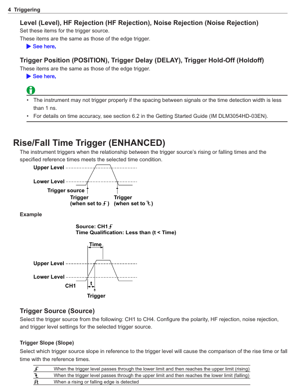
Edge triggering is the most basic triggering mode, which detects the rising/falling/double edge of the signal and is suitable for stable periodic signals (such as sine waves and square waves). The triggering source is set to "CH1" and the slope is set to "Falling" to capture the zero crossing falling signal of the power supply voltage
Pulse width trigger is triggered based on the pulse width (greater than/less than/equal to/not equal to the set value), suitable for capturing narrow pulse or wide pulse fault signals. The trigger source is set to "CH2" and the condition is set to "Width>10 μ s" to capture excessively wide pulses in the motor drive signal
Bus triggering supports CAN/LIN/SPI/I2C/UART protocols, triggered by specific frame IDs and data contents, suitable for communication signal analysis. CAN triggering: set to "ID=0x123", data "D0=0x55", captures CAN frames sent by specific ECUs
Mode triggered combination of analog and digital channel condition triggering (such as "CH1>2V and D01=1 and D02=0"), suitable for complex timing triggering conditions set to "CH3 (IGBT drive)>15V AND D05 (protection signal)=0", capturing the protection trigger when IGBT is conducting
Video triggering supports NTSC/PAL/SECAM standards, triggered by field/line, suitable for video signal testing (such as car display screen signals). The trigger source is set to "CH4", the standard is set to "PAL", and the field is set to "Even", capturing even field signals of the video
2. Analysis function (extracting key signal information)
(1) Automatic measurement
Press the "Measure" button on the front panel to enter the automatic measurement interface, and select "Add Measurement".
Select parameters from the measurement category (voltage/time/frequency/count) (such as "Vpp" peak to peak value, "Freq" frequency, "Duty" duty cycle), and specify the measurement channel (such as CH1, D01).
The measurement results are displayed at the bottom of the screen (updated in real-time), supporting the simultaneous display of 10 measurement parameters; Press the "Statistics" button to view statistical data (mean, maximum, minimum, standard deviation).
(2) Mathematical Operations and FFT Analysis
Mathematical operation: Press the "Math" key, select the operation type (such as "CH1-CH2" to calculate differential signals, "CH3 × CH4" to calculate power waveforms), set the operation range (full screen/specified area), and display the operation result waveform on the screen (default red).
FFT analysis: Press the "Math" key → "FFT", select the FFT channel (such as CH1), set the number of FFT points (128~1M points, the more points there are, the higher the frequency resolution), window function (Hanning window/rectangular window, reducing spectrum leakage), switch the screen to frequency domain display, and label the peak frequency and amplitude.
(3) Protocol decoding (communication signal analysis)
Taking CAN bus decoding as an example:
Press the "decode" key → "Add decode" → "CAN".
Set the decoding channel (such as "CH1" as CAN_S, "CH2" as CAN_L), baud rate (such as 500kbps), and protocol version (CAN 2.0A/B).
The screen displays the CAN frame decoding result (frame ID, data length, data content, frame type), which is aligned with the simulated waveform time. Clicking on the decoding entry can locate the corresponding waveform position and quickly troubleshoot communication errors (such as bit errors and CRC errors).
3. Data management (saving and exporting)
(1) Data saving types and formats
DLM3054HD supports multiple data formats to meet different usage needs:
Data Type Format Usage
Save analog/digital waveforms in. wfm (Yokogawa specific format, including waveforms and settings) and. csv (numerical format, can be imported into Excel for analysis) for later playback or data analysis
Screenshot. bmp/. png/. jpg (image format) saves the current screen display content for report generation or fault recording
Set file. set (instrument setting parameters, including channel, trigger, measurement configuration) to save commonly used test configurations, which can be directly imported for the next use without the need for repeated settings
Decoding Data. txt (text format, including protocol frame information) stores the bus decoding results for analyzing communication frame sequences
(2) Quick save operation
Press the "Save" button on the front panel, and a save menu will pop up on the screen. Select the save type (such as "Waveform" or "Screenshot").
Select the save location (USB device/internal memory), enter the file name (supports Chinese/English, default includes date and timestamp).
Press the "OK" button to complete the save. After successful saving, the screen will display a "Save Completed" prompt.
(3) PC data export
Connect the oscilloscope to the PC via a USB cable and install Yokogawa specific software (such as "Yokogawa Scope Order") to achieve:
Real time data transmission: The PC displays the waveform collected by the oscilloscope in real-time, supporting remote control of acquisition and parameter settings.
Batch data export: Export the. wfm/. csv files from the oscilloscope's internal memory or USB device to a PC and perform secondary analysis using Excel or MATLAB.
Maintenance and troubleshooting
1. Daily maintenance
Cleaning: Use a dry soft cloth to wipe the display screen and housing. If there are stains, dip a small amount of water to wipe them (do not use solvents such as alcohol and acetone to avoid damaging the coating); If there is dust on the BNC terminal and USB interface, it can be blown clean with compressed air (pressure ≤ 0.3MPa).
Probe maintenance: Regularly check whether the probe cable is damaged and whether the probe tip is oxidized (lightly polish with fine sandpaper during oxidation); Simulate probe calibration every 6 months to ensure measurement accuracy (can be done using the oscilloscope's built-in "Probe Calibration" function or sent for calibration).
Storage media: USB devices and SD cards (if any) need to be formatted regularly (using oscilloscope formatting function) to avoid file fragmentation affecting storage speed; Long term unused storage media should be stored in a dry environment to prevent data loss.
2. Troubleshooting
Possible causes and solutions for the fault phenomenon
Power cord not connected properly, power switch not turned on, internal power failure. Check the power cord connection and confirm that the power switch is turned on; If there is still no response, contact Yokogawa for repair
The waveform has no display, the channel is not turned on, the probe is not connected/damaged, the trigger is not set correctly, and the signal is not input. Press the channel key to turn on the corresponding channel, check the probe connection and attenuation ratio, reset the trigger source and threshold, and confirm that the measured signal is normal
Unstable trigger threshold inappropriate, excessive signal noise, incorrect trigger source selection. Fine tune the trigger threshold to the signal edge, turn on "trigger filtering" (reduce noise interference), and replace with a more stable trigger source
Data saving failed due to unrecognized USB device, full storage medium, unsupported file format. Re plug and unplug the USB device, delete useless files to free up space, and select a format supported by the oscilloscope (such as. wfm/. csv)
Remote control failed due to network disconnection, IP address mismatch, VISA driver not installed. Check Ethernet/USB connection, confirm that oscilloscope and PC IP are in the same network segment, and reinstall VISA driver
3. Calibration and Maintenance
Calibration cycle: It is recommended to conduct a comprehensive calibration once a year. You can contact the authorized service center of Yokogawa or refer to the "User Calibration Manual" for self calibration (requiring a standard signal source, such as Yokogawa FG420 function generator).
Maintenance restrictions: It is prohibited to disassemble the instrument by oneself (disassembly will void the warranty). If there is a hardware failure (such as abnormal channel or damaged screen), please contact Yokogawa Global Service Center (contact information can be found in PIM 113-01Z2) and have it repaired by a certified engineer.
- YOKOGAWA
- Reliance
- ADVANCED
- SEW
- ProSoft
- WATLOW
- Kongsberg
- FANUC
- VSD
- DCS
- PLC
- man-machine
- Covid-19
- Energy and Gender
- Energy Access
- Renewable Integration
- Energy Subsidies
- Energy and Water
- Net zero emission
- Energy Security
- Critical Minerals
- A-B
- petroleum
- Mine scale
- Sewage treatment
- cement
- architecture
- Industrial information
- New energy
- Automobile market
- electricity
- Construction site
- HIMA
- ABB
- Rockwell
- Schneider Modicon
- Siemens
- xYCOM
- Yaskawa
- Woodward
- BOSCH Rexroth
- MOOG
- General Electric
- American NI
- Rolls-Royce
- CTI
- Honeywell
- EMERSON
- MAN
- GE
- TRICONEX
- Control Wave
- ALSTOM
- AMAT
- STUDER
- KONGSBERG
- MOTOROLA
- DANAHER MOTION
- Bentley
- Galil
- EATON
- MOLEX
- Triconex
- DEIF
- B&W
- ZYGO
- Aerotech
- DANFOSS
- KOLLMORGEN
- Beijer
- Endress+Hauser
- schneider
- Foxboro
- KB
- REXROTH
- YAMAHA
- Johnson
- Westinghouse
- WAGO
- TOSHIBA
- TEKTRONIX
- BENDER
- BMCM
- SMC
- HITACHI
- HIRSCHMANN
- XP POWER
- Baldor
- Meggitt
- SHINKAWA
- Other Brands
- UniOP
- KUKA
- IBA
- Beckhoff
-
LTI SC52.0040.0012.0000.0 - Servo Drive
-
Lti SC52.0040.0012.0000.0 - Servo Drive
-
Milton Industries LTI Tool By Milton LT1240 - 1/2" Drive Lugnut Remover
-
LTi Drives SO84.200.P030.0000.0-W - Servo Spindle Drive
-
LTI DRIVES LSP08-035-320-30-B0R1PY170 - Servo Motor
-
LTI DRIVES SE84.200.SC00.0001.0-W - Servo Drive
-
Lust CDE34.005.W2.2 - Lti Drives Controller
-
LTi SO84.012.0030.0011.2 - ServoOne Servo Drive
-
LTi Drives SO CM-P.0010.11.00.0 - Servo Drive Controller
-
LTi CDE34.017.W3.0 - Servo Drive
-
LTI Drives CDB32.004, C2.0,SH - Positioning Controller
-
LUST CM-CAN1 - LTi DRIVES Communication Module
-
LTi SO84.012.1030.0000.2 - Servo Drive
-
LTI MOOG CDE54.044 - PITCHMASTER FREQUENCY CONVERTER 181-01019
-
MOOG LTI 181-01019 CDE54.044 - PITCHMASTER FREQUENCY CONVERTER
-
Lust LTi Drives CDE34.010,D2.0 - Servo Drive Controller
-
LTI SO84.032.0003.0101.2 - Servo Drive
-
Seagate 9CC132-302 Harris LTI-CS IRT-34-0021-01 - Hard Drive 160GB
-
LTI SO84.032.0003.0001.2 - Servo Drive
-
LTI SO24.007.0070.0000.1 - SERVO CONTROLLER
-
LTi drive CDA32.003.C3.0.H05-01.PC1 - Servo Drive
-
LTI SO84.016.0030.0000.2 - SERVO CONTROLLER
-
LUST LTI CD A34.008,W1.4, BR - SERVO DRIVE
-
MOOG LTI 181-01019 CDE54.044 - PITCHMASTER FREQUENCY CONVERTER
-
LTI MOOG 181-01019 - PITCH Master Servo Drive CDE54.044
-
LTI SERVO ONE SO84.045.0030.0001.2-W - Drive
-
LUST LTi SO84.032.0040.0000.2 - SERVO ONE DRIVE
-
LTi Drives LSH-074-2-30-3 20/T1,G6.1M - SERVO MOTOR
-
LTI SO84.016.0000.0101.2 - servo drive
-
LTI SA54.0550.0033.0000.0 - Servo Drive
-
LTI SA54.0550.0033.0000.0 - Servo Drive
-
LTI LT 4850 - 3/8" Drive 3-Pc Twist Socket Transmission Drain Plug Removal System
-
LTI Tools LT4400-30 Lock Technology - 3/4" Twist Socket 1/2" Drive Lugnut Remover
-
LTI Tools LT-1400C - 1/2 Drive Wheel Torque Extension Tool
-
LTI Tools LT1250 - 1/2" Drive Dual Sided Socket Lug Nut Remover Tool
-
LTI SO84.032.0003.0101.2 - Servo Drive
-
LTI MOOG 181-01019 - PITCH Master Servo Drive CDE54.044
-
MOOG LTI 181-01019 CDE54.044 - PITCHMASTER FREQUENCY CONVERTER
-
MOOG LTI 181-01019 CDE54.044 - PITCHMASTER FREQUENCY CONVERTER
-
MOOG LTI 181-01019 CDE54.044 - PITCHMASTER FREQUENCY CONVERTER
-
LTI SA54.0550.0033.0000.0 - Servo Drive
-
LTI Tools LT-4800 - 7 Piece Twist Socket 3/8" Drive Oil Drain Plug Removal Set
-
LTI SA54.0550.0033.0000.0 - Servo Drive
-
LTI Drive SO24.007.00300000.0 - Servo Drive
-
LTI TOOLS LTI 1400-I - Drive Wheel Torque Extension
-
LTI Tools LT4400-3 - 3/4" 19mm Twist Socket 1/2" Drive Lugnut
-
LTI TOOLS LTI 1400-BB - Drive Wheel Torque Extension
-
LTI SO84.032.0003.0101.2 - Servo Drive
-
LTI Tools LT-4512 - 3/8" Drive 12mm Twist Socket
-
LTI MOTION Luster SO84.032.0003.0001.2 - Servo Drive
-
LTI Tool By Milton LT1600P - 1" Drive Torx Stick
-
LTI Lust VF1424L,HF,OP2,S56 - Variable Frequency Drive
-
LUST CDA32.004,C1.4,H08,B0 - SERVO DFRIVE CM-CAN1 Module
-
LTI SO84.045.0002.0001.2-W - Drive
-
LTI Lust VF1404M,C9,PT1,BR1 - Inverter Type VF1404M
-
LTI SA54.0550.0033.0000.0 - Servo Drive
-
LTI Tools LT-1400C - 1/2" Drive Wheel Torque Extension
-
Lust LTI DRiVES CDA32.006, C3.0, H09 - Variateur De Fr茅quence Frequency Inverter
-
LTI MOOG CDE54.044 - PITCH master SERVO DRIVE
-
LTI MOOG CDE54.044 - PITCH master SERVO DRIVE
-
LTI SO84.143.0020.0101.2-W - servo drive
-
LTI MOTION SC34.0200.0011.0000.0 - Servo drives
-
LTI SO84.032.0003.0001.2 - Servo Drive
-
LTI DRIVES GmbH MS100 - Assembly Set Mounting Kit
-
LTI SO84.032.0003.0001.2 - Servo Drive
-
LTI SO84.032.0003.0001.2 - Servo Drive
-
LTI MOTION SO84.032.0003.0101.2 - servo drive
-
LTI SO84.032.0003.0101.2 - Servo Drive
-
LTI MOOG CDE54.044 - PITCH master SERVO DRIVE
-
LTI MOTION CDE32.004.C2.4 - Servo drives
-
LTI CDD34.032锛學x.x锛孊R锛孭C1 - Servo Drive
-
Lust LTI DRiVES CDA32.006, C3.0, H09 - Inversor De Frecuencia Frequency Inverter
-
Lust SO84.008.0030.1000.0 - Servo One LTi Drive
-
LTI MOTION SO84.032.0003.0101.2 - Servo drives
-
LUST LTi CDA32.004,C1.4 - SERVO DRIVE
-
LTI MOOG CDE54.044 - PITCH Master SERVO DRIVE
-
LTI KEBA CDB32.004 C2.7, SH - PN: 08673530 Frequency Inverter
-
LTI Tools LT-1400C - 1/2" Drive Wheel Torque Extension
-
LTI LT1400-E - 1/2" Drive Wheel Torque Extension
-
LTI MOOG 181-01019 - PITCH master SERVO DRIVE CDE54.044
-
LTI LSN-097-0510-30-560/T1 - Actuator Motor
-
LTI Tools LT 4800 - 7 Piece 3/8" Drive Twist Socket Oil Drain Plug Removal System
-
LTI DRIVES GmbH MS100 - MONTAGESET Assembly Set Mounting Kit
-
Lti SC52.0040.0012.0000.0 - Servo Drive
-
LTI DRIVES GmbH MS100 - Juego De Montaje Assembly Set Mounting Kit
-
LTi DSM4-14.2-21R83-200 - Drives servomoteur Servo Motor
-
MOOG CDE 54.044.GDA - Pitch Master Industrielle Turbine Lti Drive
-
LTI SO24.004.0030.1000.0 - Servo Drive Controller
-
Lti MOOG CDE54.044 - Pitch Master Servo Drive
-
Lust LTI DRiVES CDA32.006, C3.0, H09 - Inverter
-
LTI MOTION GMBH CDB34.006,W3.0,PC1,H39 - Frequency inverter
-
LTI SO84.032.0003.0001.2 - Servo Drive
-
MOOG CDE 54.044.D - Pitch Master Industrielle Turbine Lti Drive
-
LTI TOOLS LT-1460 - 1/2" DRIVE WHEEL TORQUE EXTENSION KIT 5 PIECE SET
-
Lust Cdb32.003, C2.4 - Lti Drives Servoregulador Frecuencia Servo Controller Inverter
-
Lust LTI DRIVES CDA32.006, C3.0, H09 - Frequency Inverter
-
Lust Lti SO82.004.0030.0000.2 - Servo Drive
-
LTI MOTION SC34.0200.0011.0000.0-SL - Servo drives
-
LTI MOTION SA54.0075.0033.0000.0 - Servo drives
-
LTI MOTION SC32.0075.1011.0000.0 - Servo drives
-
LTI Servo-One Junior SO22.006.0080.1000.0 - Servo Controller Servoregler
-
LUST CDA32.004, C1.4, H08, B0 - Servo Drive & LTI CM-CAN1 Module
-
LTI DRIVES LSP08-035-320-30-B0R1PY170 - Servo Motor
-
LUST LTI CDA32.004,C1.4.H08.B0 - SERVO CONTROLLER DRIVES
-
LUST LTi DRiVES CDS44.072LC1.2 - Servo Drive
-
Lti Servo-One Junior SO22.006.0082.1000.0 - Servo Controller Servoregler
-
LUST CDA32.008,C2.0,HF - Lti DRIVES Spindle Drive Inverter
-
LTI SO22.003.0082.0000.0 - Servo Drives One junior Servo Controller Servoregler
-
Lust Lti Drives CM-CAN1 - Communication Module
-
LUST Lti Drives Vf1202s, G8, I6 - Frequency Inverter Drive
-
LTI DRIVES BR-090.03.540.UR.H38 - Bremswiderstand Brake Resistor
-
LTi DRIVES PM-E40.2DRA054P - Wind Turbine Pitch Control Inverter
-
LTi Drives GmbH br-110.01.540-UR - Brake Resistor
-
LTI Drives LSN-097-0960-30-0560/T1,S4,B - Servo Motor
-
LUST CDA34.006.C2.0 - LTI Drives Servoregler
-
LUST LTI DRIVES SERVO ONE JUNIOR SO24.002.0020.0000.1 - Servo Drive Controller
-
LTI MOTION SO84.032.0003.0001.2 - Servo drives
-
LTI DDTD750V2-120 - IBOP ACTUATOR CYLINDER FOR TOP DRIVE
-
LTI CDE32.004, C2.4 - SERVO DRIVE
-
LUST LTI DRIVES CDD34.017 W3.4PC1 - Servo Drive Controller
-
LTI CDA3208,C3,0,HF - AC SERVO DRIVE
-
LUST LTI DRIVES LSH-074-3-30-560/T1,G6.1S - SERVO MOTOR
-
LUST Lti CDB32.004.C2.4.SH - AC Servo Drive
-
LTi CDA32.006, C3.0, H09 - Servo Drive
-
LTI SO22.003.0010.0000.0 - Servo Drive Servo one junior Servoregler Controller
-
LTi Drives DSM4-14.2-21R83-200 - Servo Motor
-
LUST Lti Drives Lsh-097-1-30-560/T1, 1R - Servomotor
-
LTI 1237 - 7 Piece 1/2" Drive Flip Socket Set

K-JIANG

Add: Jimei North Road, Jimei District, Xiamen, Fujian, China
Tell:+86-15305925923