
K-WANG


DEIF LSU-112DG Load Distribution Unit
DEIF LSU-112DG Load Distribution Unit
Basic Product Information
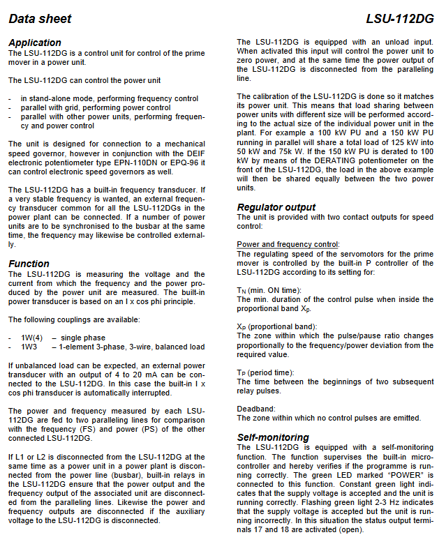
LSU-112DG is a generator load distribution unit developed by DEIF, with ANSI code 90. Its core is used for prime mover control of diesel and gas generators, achieving frequency and power control of generators and precise load distribution when multiple generators are connected in parallel. The product is installed on a 35mm DIN rail or base, equipped with LED status indicator lights (displaying device operating status and activated control functions), built-in microcontroller for core logic control, and self-monitoring function. The overall design is suitable for industrial, maritime and other generator control scenarios, document number 4921240118I.
Core Application Mode and Governor Adaptation
Three operating modes
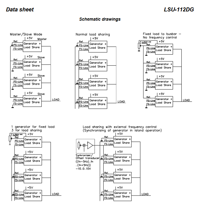
LSU-112DG can achieve three types of precise control according to the operating scenario of the generator, covering the entire scenario from single machine to multi machine parallel connection:
Single machine mode: Independently control the generator, execute frequency control, and maintain stable output frequency of the generator;
Grid connected mode: The generator is connected in parallel with the power grid, and power control is performed to stabilize the output power according to the set value;
Multi machine parallel mode: operates in parallel with other generators, while performing frequency and power control to achieve reasonable load distribution among multiple units.
Governor adaptation
Native support for direct connection of mechanical speed controllers;
Paired with DEIFEPN-110DN or EPQ-96 electronic potentiometers, it can be extended to support electronic speed controllers and adapt to different types of generator speed control systems.
Core Measurement and Sensing Functions
Built in sensors
Built in frequency sensor: enables precise measurement of generator frequency. If higher frequency stability is required, an external common external frequency sensor can be connected (applicable to all LSU-112DG in the power station);
Built in power sensor: designed based on the I × cos φ principle, supports two types of wiring coupling methods, with 1W3 (three-phase three wire, balanced load) as the standard configuration and 1W (4) as single-phase coupling, meeting the measurement needs of different power supply systems.
Expansion of External Sensors
Power sensor: When there is an unbalanced load on the generator, an external power sensor with a 4-20mA DC output can be connected (recommended DEIF TAS-331DG). At this time, the built-in power sensor will automatically disconnect and the external sensor will take over the measurement;
Frequency sensor: When multiple generators are synchronized to the bus at the same time, an external frequency sensor can be connected to control the frequency uniformly and improve synchronization accuracy.
Core Control and Protection Functions
Proportional load distribution (core function)
LSU-112DG needs to be calibrated according to the actual capacity of the corresponding generator to achieve proportional load distribution when different capacity units are connected in parallel. For example, if a 100kW+150kW unit is connected in parallel, the total load of 125kW will be divided into 50kW and 75kW according to a 4:6 ratio;
Equipped with a positive Derating potentiometer, the large unit can be operated at a reduced capacity (with an adjustment range of 50~0% P ₙ). After the reduction, the load of the unit will be evenly distributed according to the reduced capacity. For example, if a 150kW unit is reduced to 100kW, it will share a load of 125kW (62.5kW each) with the original 100kW unit.
Speed Control Output
The unit is equipped with 2 relay contact outputs (speed up SG/speed down SG) for controlling the servo motor of the prime mover. The speed control logic is implemented by the built-in P controller, and the control accuracy is adjusted through three core parameters. The parameters can be set as needed:
TN (minimum on-time): The minimum duration of control pulses within the proportional band, ranging from 25 to 500ms;
XP (Proportional Band): The interval in which the pulse/pause ratio varies proportionally with frequency/power deviation, ranging from 0 to ± 50% P ₙ or 0 to ± 2.5Hz set frequency;
TP (cycle time): The interval time between two consecutive relay pulses, default 10 × TN, can be set to 5 × TN/15 × TN/20 × TN through jumper wires.
Simultaneously set dead zone: the deviation interval without control pulse output, the power dead zone defaults to * * ± 2% P ₙ * * (jumper can be set to ± 4%), and the frequency dead zone defaults to * * ± 0.1Hz * * (jumper can be set to ± 0.25Hz).
Unloading function
Equipped with a potential free unloading input (33/34 terminals), two core actions are achieved after activation:
Adjust the generator power to zero power;
Disconnect the power output and power parallel line (PS) of LSU-112DG to avoid interference with other parallel units.
Automatic protection and disconnection
When the following situations occur, the built-in relay will automatically disconnect the power/frequency output of the unit from the parallel line (PS/FS) to ensure system stability:
The L1/L2 phase of LSU-112DG is disconnected, and the corresponding generator is disconnected from the busbar;
The auxiliary power supply voltage of LSU-112DG is disconnected;
When the unloading input is activated (only disconnect the power parallel line PS).
Self monitoring function
Built in microcontroller program running status self-monitoring, feedback through green POWER LED light and 17/18 status output terminal:
Green light constantly on: power supply is normal, unit operation is correct, 17/18 terminals are closed;
Green light flashing at 2-3Hz: power supply is normal, unit operation is faulty, 17/18 terminals are disconnected (activated fault state).
Key Terminals and Signal Output
The LSU-112DG is equipped with multiple sets of functional terminals, covering all requirements such as power supply, measurement, control, parallel connection, and expansion. The core terminal functions are shown in the table below (key terminals):
Terminal number identification/name, core function, key parameters/description
1/3 X1/X2 power supply voltage input AC 57.7~690V/DC 24~110V, UL only supports 24V DC/110V AC
17/18 Sta (status) status output closed normally, fault disconnected
28/29 IL1 current measurement input external current transformer S1 → 28, S2 → 29
31/32 Ext. P. (External Power) External power sensor input 4-20mA DC, built-in sensor needs to be short circuited when in use
33/34 Unl (Unloading) Unloading input connected to a potential free normally open relay contact, activated to zero power
35/36 Ref./⊥ (reference/ground) power reference input 0.5~5V corresponds to 10~100% power, 0.55V activated/0.45V deactivated
37/36+5V/⊥ reference voltage output 5.0V ± 1%, maximum load 5mA, used for local power control
38/39 FS/⊥ frequency parallel line -5~+5V analog quantity, 0V=0Hz, 5V=2.5Hz
40/41 PS/⊥ power parallel line -5~+5V analog quantity, 5V=100% power (when cos φ=0.8, 4V=100%)
43/44, 45/46 SG (speed up/down) speed control relay outputs AC1/DC1: 250V/24V 8A; AC15/DC13:250V/24V 3A
Note: All terminals marked with ⊥ are interconnected internally; When connecting a DC servo motor, the SG relay needs to be externally connected to an auxiliary relay, and transient suppressors should be connected at both ends of the relay coil.
Technical Specifications (Key Parameters)
Measurement specifications
Measurement parameter range/specification, overload capacity, load requirements
Measure current (I ₙ) 0.3~1.5A AC (calibration module), UL version 0.4~5.0A AC 20 × I ₙ for 10 seconds (maximum 75A); Maximum 0.5VA per phase at rated current of 80 × I ₙ for 1 second (maximum 300A)
Measure voltage (U ₙ) 57.7~690V AC, UL version 57.7~450V AC 1.2 × U ₙ Continuous operation 2k Ω/V
Electrical output specifications
Key Explanation of Output Type Range/Accuracy
PS/FS parallel line -5~+5V, 5V ± 2%=2.5Hz/100% power dual analog parallel line, realizing multi machine data exchange
Reference voltage output 5.0V ± 1% maximum load 5mA (R ≥ 1k Ω), UL version ± 5V DC
Optocoupler output maximum 30V DC/5mA, voltage drop 1.5V@2mA Output shutdown in case of system failure, UL version 30V DC/5mA
Speed control relay output AC1/DC1:8A; AC15/DC13:3A UL version only supports resistive loads
Environmental and Physical Specifications
Project Specification UL/cUL Version Special Requirements
Working temperature -25~70 ℃ (-13~158 ℉), maximum ambient temperature 60 ℃ (140 ℉)
Temperature drift setting value maximum ± 0.2% full-scale/10 ℃ same as left
Electrical isolation measurement/relay/analog IO/auxiliary power supply room 3250V AC 50Hz 1min same as left
Protection level: enclosure IP40, terminal IP20 (IEC/EN 60529) same as left
All plastic parts are made of UL94-V1 self extinguishing material, the same as the left
Weight approximately 0.750kg on the left
Wiring specifications: single strand maximum 4.0mm ², multi strand maximum 2.5mm ²; AWG 12-16 copper wire only uses 60/75 ℃ copper conductor
Other certifications and standards
EMC: Compliant with IEC/EN 61000-6-1/2/3/4;
Climate grade: DIN 40040 HSE grade;
Classification Society Certification: Uni line series components have been recognized by mainstream maritime classification societies, and the latest certification can be found on the DEIF official website;
UL certification: Provided on demand. If the product is re customized outside the DEIF Denmark factory, it will lose UL certification.
Adjustable Parameters and LED Indication
Core Adjustable Parameters (Range)
The control parameters of LSU-112DG can be adjusted as needed, and the core parameter adjustment range is shown in the table below. The jumper can expand the parameter range of some parts:
Parameter Name Adjustment Range Remarks
TN (Minimum Connection Time) 25~500ms Basic Speed Control Parameters
XP (proportional band) 0~± 50% P ₙ/0~± 2.5Hz Set frequency, choose one, configure according to control requirements
Set the frequency to 45-65Hz to cover the mainstream generator frequency standard
Derating 50~0% P ₙ adjusted according to the unit's derating requirements
TP (cycle time) 10 × TN (jumper can be set to 5/15/20 × TN) and TN linkage
Power dead zone ± 2% P ₙ (jumper can be set to ± 4%) After derating, calculate according to the derating value
Frequency dead zone ± 0.1Hz (jumper can be set to ± 0.25Hz) to reduce ineffective speed regulation pulses
LED Status Indication
Equipped with multi-color LED lights, providing intuitive feedback on the operation status of the equipment and generator. If there are no additional indicator lights, it means that the corresponding function is not activated:
LED identification function is constantly on (status) and off (status)
UG (green) generator voltage is normal, but there is a voltage fault
Unload (green) The generator unloading unit has been unloaded (zero power) and is operating at normal load
SG (yellow) speed up/down control corresponding to speed up/down relay activation relay not activated
Note: After the equipment installation and calibration are completed, the transparent front cover can be sealed to prevent parameters from being mistakenly modified.
- YOKOGAWA
- Reliance
- ADVANCED
- SEW
- ProSoft
- WATLOW
- Kongsberg
- FANUC
- VSD
- DCS
- PLC
- man-machine
- Covid-19
- Energy and Gender
- Energy Access
- Renewable Integration
- Energy Subsidies
- Energy and Water
- Net zero emission
- Energy Security
- Critical Minerals
- A-B
- petroleum
- Mine scale
- Sewage treatment
- cement
- architecture
- Industrial information
- New energy
- Automobile market
- electricity
- Construction site
- HIMA
- ABB
- Rockwell
- Schneider Modicon
- Siemens
- xYCOM
- Yaskawa
- Woodward
- BOSCH Rexroth
- MOOG
- General Electric
- American NI
- Rolls-Royce
- CTI
- Honeywell
- EMERSON
- MAN
- GE
- TRICONEX
- Control Wave
- ALSTOM
- AMAT
- STUDER
- KONGSBERG
- MOTOROLA
- DANAHER MOTION
- Bentley
- Galil
- EATON
- MOLEX
- Triconex
- DEIF
- B&W
- ZYGO
- Aerotech
- DANFOSS
- KOLLMORGEN
- Beijer
- Endress+Hauser
- schneider
- Foxboro
- KB
- REXROTH
- YAMAHA
- Johnson
- Westinghouse
- WAGO
- TOSHIBA
- TEKTRONIX
- BENDER
- BMCM
- SMC
- HITACHI
- HIRSCHMANN
- XP POWER
- Baldor
- Meggitt
- SHINKAWA
- Other Brands
- UniOP
- KUKA
- IBA
- Beckhoff
- ADLINK
-
Beckhoff CP7232-0001-0030 - Control Panel PC HMI
-
Beckhoff CX5020-0122 - Embedded PC CPU Module
-
Beckhoff AM8043-0H10-0000 - Rotary Synchronous Servo Motor
-
Beckhoff CP3924-0010 - Multitouch Control Panel HMI
-
Beckhoff CX9020-0110-1005 - Embedded PC Basic CPU Module
-
Beckhoff BK9105 - EtherNet/IP Bus Coupler
-
Beckhoff CX1500-M310 - Profibus Master Fieldbus Extension Module
-
Beckhoff CX1500-M510 - PROFIBUS Master Fieldbus Extension Module
-
Beckhoff CP9922.0 - TTL-TX Display Transmitter Card
-
Beckhoff CP9010_1 - ISA Slot Interface Card
-
Beckhoff NRL75-DC30S15B - LCD Inverter Board
-
Beckhoff LTD121C30S - Toshiba LCD Display Panel
-
Beckhoff CP7732-1207-0030 - Operating Terminal Panel PC HMI
-
Beckhoff C5102-0010 - Rackmount Industrial Computer PC5000
-
Beckhoff C6015-0010 - Ultra-Compact Industrial PC
-
Beckhoff CB1056-0001 - Industrial PC Motherboard Mainboard
-
Beckhoff AX5103 - Digital Compact Servo Amplifier 1 Axis
-
Beckhoff AM8052-0J00-9000 - Rotary Synchronous Servo Motor
-
Beckhoff CP7932-0002-0000 - Control Panel HMI Display
-
Beckhoff CB1061-0001 - Industrial PC Motherboard Mainboard
-
Beckhoff C5102-0060 - 19-inch Rackmount Industrial PC
-
Beckhoff EL7342 - 2 Channel DC Motor Motion Interface EtherCAT Terminal
-
Beckhoff CX5120-0135 - Embedded PC CPU Module Intel Atom
-
Beckhoff CB1061-G4 - Industrial PC Motherboard Mainboard
-
Beckhoff CX50100121 - Embedded PC CPU Module
-
Beckhoff CX1030-0013-1002 - Basic CPU Module Intel Pentium M
-
Beckhoff CP7802-1075-0010 - Control Panel Touch Screen HMI
-
Beckhoff AM8023-0E20-0000 - Rotary Synchronous Servo Motor
-
Beckhoff EL5032 - 2 Channel Encoder Interface EnDAT EtherCAT Terminal
-
Beckhoff CX5130-0175 - Embedded PC CPU Module Intel Atom
-
Beckhoff CA4040-0000 - PCI Ethernet Network Board
-
Beckhoff C3340 - Panel PC Industrial Workstation
-
Beckhoff EL3068 - 8 Channel Analog Input EtherCAT Terminal 0-10V
-
Beckhoff EL1889 - 16 Channel Digital Input EtherCAT Terminal
-
Beckhoff C6640-0050 - Control Cabinet Industrial PC Intel Core i7
-
Beckhoff PC MIC 3230 TP - Industrial Panel PC Touch Screen
-
Beckhoff CX2040-0135 - Embedded PC Industrial CPU Module
-
Beckhoff CP6202-1020-0010 - Built-in Panel PC HMI
-
Beckhoff KL3001 - 1 Channel Analog Input Bus Terminal 0-10V
-
Beckhoff C6920-1047-0030 - Control Cabinet Industrial PC
-
Beckhoff CX5140-0122 - Embedded PC CPU Module
-
Beckhoff AX5106-0000-0200 - Digital Compact Servo Amplifier 1 Axis
-
Beckhoff EL2904 - 4 Channel Digital Output TwinSAFE EtherCAT Terminal
-
Beckhoff AM8053-1GH1-0000 - Rotary Synchronous Servo Motor
-
Beckhoff EL4021 - 1 Channel Analog Output 0-20mA Bus Terminal
-
Beckhoff CX5010-0121 - Embedded PC CPU Module
-
Beckhoff C6925-0020 - Control Cabinet Industrial PC
-
Beckhoff CX9010-N000 - Virtual Fieldbus Interface Module
-
Beckhoff CX9010-N031 - System Interface Module RS232
-
Beckhoff CX9010-N010 - System Interface Module DVI USB
-
Beckhoff CX9010-1101 - Basic CPU Module
-
Beckhoff CX8080 - Embedded PC Controller Module
-
Beckhoff C6909-0001-0000 - Built-in Control Panel HMI Touch Screen
-
Beckhoff ELM3502-0000 - 2 Channel Measuring Bridge EtherCAT Terminal
-
Beckhoff CX2040-0100 - Embedded PC CPU Controller Module
-
Beckhoff CX2072-0155 - Embedded PC Intel Xeon CPU Base Module
-
Beckhoff EL4732 - 2 Channel Analog Output EtherCAT Terminal Oversampling
-
Beckhoff CP6907-1000-000 - Built-in Control Panel Operator HMI
-
Beckhoff B310-0000 - Fieldbus Box PROFIBUS Interface
-
Beckhoff IP3112 - Fieldbus Box 4 Channel Analog Input PROFIBUS
-
Beckhoff AM8023-0F21-0000 - Rotary Synchronous Servo Motor
-
Beckhoff AX2090-L805-0001 - Shield Connection Motor Module
-
Beckhoff AM8053-0L2B-0000 - Rotary Synchronous Servo Motor
-
Beckhoff CP7803-0011-0010 - Control Panel HMI Display
-
Beckhoff CP2919-0000 - Multi-Touch Built-in Control Panel HMI
-
Beckhoff CX5020-0125 - Embedded PC CPU Module
-
Beckhoff CP3924-000 - Multitouch Control Panel HMI
-
Beckhoff C6930-0040 - Control Cabinet Industrial PC Core i5
-
Beckhoff CX5020-0121 - Embedded PC CPU Module
-
Beckhoff CX5020-0100 - Embedded PC CPU Module
-
Beckhoff CX1030-0121 - Basic CPU Module Intel Pentium M
-
Beckhoff EP2349-0021 - EtherCAT Box Multi Directional Digital I/O
-
Beckhoff CX1020-0012 - Basic CPU Module
-
Beckhoff CP6929-0001-0000 - Built-in Control Panel Touch HMI
-
Beckhoff CX9020-0115 - Standard PLC Module CPU Unit
-
Beckhoff CP7803-0001-0010 - Control Panel HMI Display
-
Beckhoff CX1900-0025 - Compact Flash Memory Card
-
Beckhoff HUSKY PC#6 - Industrial PC Sercos Card Interface
-
Beckhoff EK1818-0000 - EtherCAT Coupler Digital Input Output Module
-
Beckhoff EL4112-0010 - 2 Channel Analog Output EtherCAT Terminal
-
B&R 4P3040.01-490 - Control Panel HMI
-
B&R 5PC600.SX05-01 - Industrial Computer System Unit
-
Beckhoff CX5130-0121 - Embedded PC CPU Module
-
Beckhoff C6515-1001-0000 - Fanless Built-in Industrial PC
-
Beckhoff AX5106-0000-0200 - Digital Compact Servo Amplifier 1 Axis
-
Beckhoff CP6829-0001-0000 - Built-in Control Panel Touch HMI
-
Beckhoff CX2040-0100 - Embedded PC CPU Quad Core Module
-
Beckhoff CX5140-0175 - Embedded PC CPU Module Intel Atom
-
Beckhoff EK1322 - 2 Port EtherCAT P Junction Module
-
Beckhoff C6650-0020 - Control Cabinet Industrial PC
-
Beckhoff C6525-0030 - Fanless Built-in Industrial PC
-
Beckhoff CP7232-0002-0020 - Control Panel PC HMI
-
Beckhoff CP2916-0000 - Multi-Touch Control Panel HMI Display
-
Beckhoff C6920-0050 - Control Cabinet Industrial PC
-
Beckhoff EL2828 - 8 Channel Digital Output EtherCAT Terminal
-
Beckhoff AX5103-0000-0200 - Digital Compact Servo Amplifier 1 Axis
-
Beckhoff CX2020-0121 - Embedded PC CPU Module
-
Beckhoff CP3918-1012-0000 - Multitouch Control Panel HMI
-
Beckhoff FC3101 - Profibus PCI Fieldbus Interface Card
-
Beckhoff C6220 - Control Cabinet Industrial PC
-
Beckhoff CX9020-0111 - Embedded PC CPU Module Base Unit
-
Beckhoff CP6911-0001-0000 - Installation Control Panel HMI
-
Beckhoff CX2100-0004 - Power Supply Module E-bus Coupler
-
Beckhoff CP6700-0500 - Built-in Panel PC Touch Screen HMI
-
Beckhoff CP7902-1235-0000 - Control Panel Touch Screen
-
Beckhoff CB3054-0001 - Industrial PC Motherboard
-
Beckhoff CX1020-N031 - System Interface Module
-
Beckhoff CX1100-0002 - Power Supply Module
-
Beckhoff CX1020-0100 - Basic CPU Module
-
Beckhoff C6032-0060 - Ultra-Compact Industrial PC
-
Beckhoff C6140 - Control Cabinet Industrial PC Intel Celeron
-
Beckhoff CX5120-0111 - Embedded PC CPU Module
-
Beckhoff CP6202-0001-0010 - Built-in Panel PC HMI
-
Beckhoff CP6222-0001-0030 - Built-in Panel PC HMI
-
Beckhoff CP6706-0001-0050 - Built-in Panel PC HMI
-
Beckhoff C6017-0010 - Ultra-Compact Industrial PC
-
Beckhoff CP6202-1029-0020 - Built-in Panel PC HMI
-
Beckhoff AX5805 - TwinSAFE Drive Option Card
-
Beckhoff AX5206-0000-0202 - Digital Compact Servo Amplifier 2 Axis
-
Beckhoff CP2216-0010 - Multi-Touch Built-in Panel PC HMI
-
Beckhoff C6920-0060 - Control Cabinet Industrial PC
-
Beckhoff CX1020-0011 - Basic CPU Module
-
Beckhoff CX2900-0033 - Solid State Disk SSD Storage
-
Beckhoff CX1800-2031 - System Module Extension
-
Beckhoff CX2020-0120 - Embedded PC CPU Module
-
Beckhoff CP3921-1113-0010 - Multitouch Control Panel HMI
-
Beckhoff CP7701-0001-0020 - Panel PC Touch Screen AMD LX
-
Beckhoff CX5020 - Embedded PC CPU Module

K-JIANG

Add: Jimei North Road, Jimei District, Xiamen, Fujian, China
Tell:+86-15305925923