
K-WANG


Watlow plug-in heater
FIREROD ® Universal plug-in heater 1400 ° F (760 ° C) (Alloy 800 sheath) 400 W/in ² (62 W/cm ²) 60 years of industry validation, high thermal conductivity efficiency, supports multi scenario customization
High temperature FIREROD high-temperature working condition specific 1800 ° F (982 ° C) 100 W/in ² (15.5 W/cm ²) sealing design reduces oxidation, high emissivity sheath enhances heat transfer
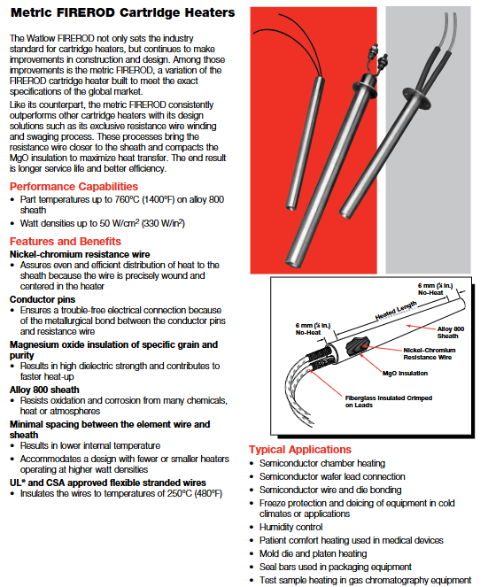
Metric FIREROD global adaptation 1400 ° F (760 ° C) 330 W/in ² (50 W/cm ²) meets metric standards, has high dimensional accuracy, and is compatible with international equipment
MULTICELL ™ Multi zone precise temperature control 2050 ° F (1120 ° C) 30 W/in ² (4.6 W/cm ²) up to 6 independent temperature control zones, loose assembly design for easy disassembly and assembly
Watlow plug-in heater
Product Family and Core Features
1. Product Line Overview
Core positioning of product series: Maximum operating temperature, maximum power density, key advantages
FIREROD ® Universal plug-in heater 1400 ° F (760 ° C) (Alloy 800 sheath) 400 W/in ² (62 W/cm ²) 60 years of industry validation, high thermal conductivity efficiency, supports multi scenario customization
High temperature FIREROD high-temperature working condition specific 1800 ° F (982 ° C) 100 W/in ² (15.5 W/cm ²) sealing design reduces oxidation, high emissivity sheath enhances heat transfer
Metric FIREROD global adaptation 1400 ° F (760 ° C) 330 W/in ² (50 W/cm ²) meets metric standards, has high dimensional accuracy, and is compatible with international equipment
MULTICELL ™ Multi zone precise temperature control 2050 ° F (1120 ° C) 30 W/in ² (4.6 W/cm ²) up to 6 independent temperature control zones, loose assembly design for easy disassembly and assembly
2. Core common advantages
Material and Structure: Made of nickel chromium resistance wire (uniform heating), magnesium oxide (MgO) insulation layer with specific grain purity (high dielectric strength, rapid heating), Alloy 800 or stainless steel sheath (anti-oxidation, corrosion-resistant).
Process design: Minimize the distance between the resistance wire and the sheath, reduce internal temperature, and support high power density operation; UL ®/ CSA certified leads, with insulation levels ranging from 250 ° C to 842 ° C.
Safety and reliability: non-volatile design, strong high-temperature stability; Some models support low leakage construction and are suitable for sensitive scenarios such as healthcare.
Detailed explanation of key technical specifications
1. Dimensions and tolerances
(1)FIREROD ® standard size
Nominal diameter (in) Actual diameter (in/mm) Minimum sheath length (in/mm) Maximum sheath length (in/mm) Diameter tolerance
1/8 0.122(3.1) 7/8(22.2) 12(305) ±0.002 in(±0.05 mm)
1/4 0.246(6.3) 7/8(22.2) 36(915) ±0.002 in(±0.05 mm)
1/2 0.496(12.6) 7/8(22.2) 60(1520) ±0.002 in(±0.05 mm)
1 0.996(25.3) 1 1/4(32.0) 72(1830) ±0.003 in(±0.08 mm)
(2) Tolerance requirements
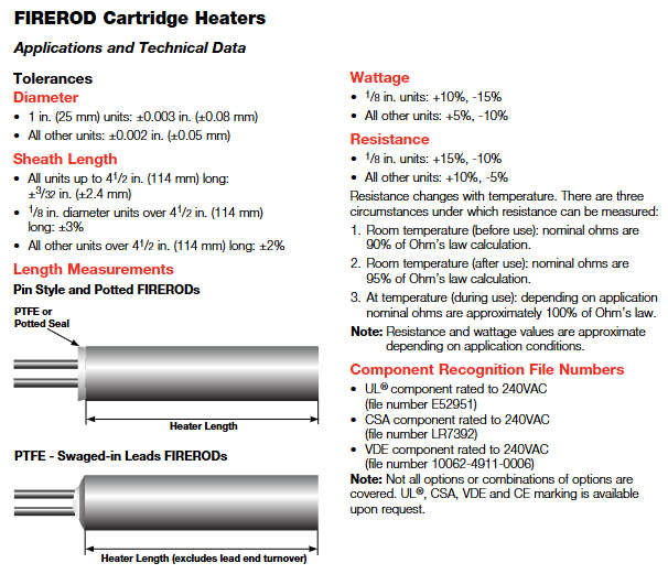
Length tolerance: The sheath with a length tolerance of ≤ 4.5 in (114 mm) is ± 3/32 in (± 2.4 mm); The sheath with a diameter greater than 4.5 inches is ± 2% (1/8 inch diameter is ± 3%).
Power tolerance: 1/8 inch diameter is+10%/-15%, other diameters are+5%/-10%.
Resistance tolerance: 1/8 inch diameter is+15%/-10%, other diameters are+10%/-5%; Resistance varies with temperature, with room temperature (before use) being 90% of the value calculated by Ohm's Law, and after use being 95%.
2. Electrical performance
(1)FIREROD ® Voltage and power range
Diameter (in) Maximum voltage (V) Maximum current (A) 120V Minimum power (W) 240V Maximum power (W)
1/8 240 3.1 - 720
1/4 240 4.4 100 1050
3/4 480 23.0 30 5520
1 480 23.0 - 5520
(2) Metric FIREROD Electrical Parameters (Example)
Diameter (mm) Maximum voltage (V) 230V Maximum power (W) 400V Maximum power (W) Maximum current (A)
6.5 250 1650 - 7.2
16 480 4830 8400 21
20 480 4830 8400 21
3. Power density and application adaptation
Power density directly affects heating efficiency and heater lifespan, and should be selected based on the heating medium and operating conditions
Metal heating: The maximum allowable power density varies with the aperture fit gap and temperature (for example, at 1400 ° F, a fit gap of 0.005 in corresponds to a power density of approximately 80 W/in ²).
Air/gas heating: At an ambient temperature of 70 ° F, the maximum allowable power density for a single heater is approximately 60 W/in ²; When multiple devices are parallel, they need to be multiplied by a correction factor of 0.95, and when equipped with a reflector, they need to be multiplied by 0.85.
Mobile air heating: The higher the wind speed, the greater the allowed power density (for example, at a wind speed of 100 FPM, the power density can reach 1000 W/in ²).
Installation and Wiring Guide
1. Installation preparation
Aperture matching: It is recommended that the aperture be 0.001-0.006 inches larger than the actual diameter of the heater (for metal heating). A gap that is too large can reduce thermal efficiency, while a gap that is too small may make disassembly difficult.
Installation location: The sensor should be installed in a temperature uniform area, away from the edge of the heat source; The sheath should be in full contact with the heating medium to avoid local overheating.
Environmental requirements: Avoid installing in close proximity to noise sources such as motors and relays; In humid environments, models with sealing (PTFE/silicone) should be selected.
2. Wiring specifications
(1) Lead type and specifications
Lead type, maximum temperature, applicable scenarios, wire diameter specifications (example)
GGS fiberglass 482 ° F (250 ° C) universal scenario 18 AWG (1/2 inch diameter heater)
MGT 842 ° F (450 ° C) high temperature scenario 18 AWG (3/4 inch diameter heater)
PTFE 392 ° F (200 ° C) corrosion-resistant scenario 20 AWG (3/8 in diameter heater)
Mineral Insulation (MI) 1500 ° F (815 ° C) Extreme High Temperature/Vibration Scenarios Conductor Diameter 0.044 in (3/8 in diameter heater)
(2) Wiring precautions
Lead length: Standard length of 12 inches (305 mm), customizable extension, extra long leads need to consider voltage drop (recommended wire diameter not less than 22 AWG).
Grounding requirements: Models with grounding leads must be reliably grounded to avoid the risk of electrical leakage; In high temperature scenarios, the lead wire should be kept away from the sheath (with a minimum length of 1 inch without thermal zone).
Multi zone control: MULTICELL ™ The heater needs to be wired separately for each temperature control zone to ensure independent adjustment.
3. Fixed method
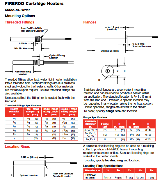
Flange fixing: Stainless steel flange (FS/FM/FL type), suitable for panel installation, flange position can be customized (standard distance from lead end 1/4 in).
Threaded fixation: 304 stainless steel or brass threaded joints (NPT/DIN specifications), waterproof installation, suitable for pipeline or threaded hole scenarios.
Positioning ring: Stainless steel positioning ring, used for non precision fixed scenarios, installed at the end of the no heat zone.
Customized Options and Selection Guide
1. Core customization options
(1) End and sealing options
Option Type Function Applicable Temperature Minimum No Hot Zone Length
PTFE seal and lead anti moisture, oil, solvent 392 ° F (200 ° C) 1 in (25 mm)
Silicone sealing and lead anti moisture, mild corrosion 302 ° F (150 ° C) 1 in (25 mm)
Epoxy resin sealing high temperature sealing (up to 260 ° C) 260 ° F (500 ° C) 1 in (25 mm)
Mineral Insulated (MI) Seal for Extreme High Temperature, Vibration, Corrosion 1500 ° F (815 ° C) 6 in (152 mm)
(2) Lead protection options
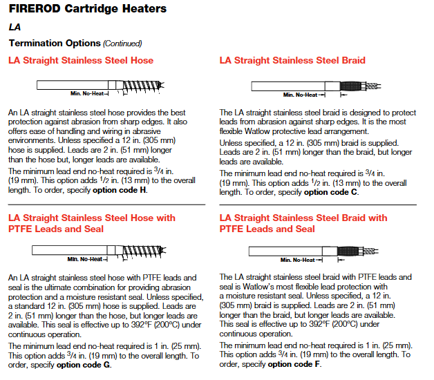
Stainless steel hose: wear-resistant, suitable for harsh environments, standard length of 12 inches, lead wire 2 inches longer than hose.
Stainless steel woven mesh: high flexibility, wear-resistant, standard length of 12 inches, supports right angle wire output.
Galvanized conduit: Abrasion protection, with 90 ° bend, standard length 8 inches.
(3) Function extension options
Built in thermocouples: Style A (monitoring the internal temperature of the heater), Style B (approximate workpiece temperature), Style C (end temperature, suitable for plastic molding), supporting J/K type.
Distributed power: Set different power densities in segments along the length of the heater to compensate for edge heat loss (suitable for scenarios such as sealing strips).
Dual voltage design: supports switching between two voltages and is suitable for multi scenario power supply (only available for metric models with diameters of 12.5 mm and above).
Extension without hot zone: The lead end or terminal without hot zone can be extended (up to 2.5 inches) to avoid the influence of high temperature on the lead.
2. Selection steps
Determine operating parameters: maximum working temperature, heating medium (metal/air/liquid), aperture and installation method.
Calculate power demand: Determine the required power based on the heating area, heating rate, and heat loss (recommended power density not exceeding the maximum allowable value of the corresponding medium).
Select product series: FIREROD for general scenarios ®, Choose high-temperature FIREROD for high temperature scenarios, metric models for international equipment, and MULTICELL for multi zone temperature control ™。
Customized function options: Select the sealing type according to the environment, choose the lead protection and fixing method according to the installation space, and select the built-in thermocouple according to the temperature control accuracy.
Maintenance and troubleshooting
1. Daily maintenance
Regular inspection: Check the insulation layer of the lead wires and the sheath for oxidation and discoloration every month, and replace them promptly if any problems are found.
Cleaning and maintenance: Remove dust and oil stains from the surface of the sheath to avoid affecting heat transfer; WATLUBE can be used for disassembly ™ Lubricant, easy to disassemble and does not affect thermal conductivity.
Life management: Under high temperature conditions (such as above 1400 ° F), it is recommended to regularly check the resistance value and replace the heater when the resistance changes by more than 10%.
2. Common faults and solutions
Possible causes and solutions for the fault phenomenon
Slow heating, insufficient power density, loose aperture fit, excessive lead voltage drop, replacement with higher power model, adjustment of aperture gap, and thickening of lead wire diameter
Improper installation position due to local overheating, poor medium contact, adjust installation position, and ensure that the protective cover is fully attached to the heating surface
Damaged leads, high temperature baking, wear, corrosion, extended no heat zone, replacement of protected lead options (hose/braided mesh), selection of corrosion-resistant seals
Excessive leakage, insulation layer affected by moisture or damage, replacement of sealing model, drying environment, and inspection of reliable grounding
High power density due to heater burnout, reduced power density due to dry burning of medium, ensuring sufficient heating medium, and installing temperature protection devices
Typical application scenarios
Semiconductor manufacturing: wafer bonding, chamber heating (using high cleanliness, low leakage FIREROD) ®, With PTFE seal).
Plastic molding: mold heating, sealing strip heating (using models with distributed power and built-in thermocouples).
Medical equipment: patient insulation, instrument heating (using low leakage, small-sized FIREROD) ®)。
Freezing protection: Anti icing of equipment in low-temperature environments (using high-power density, waterproof sealing models).
High temperature process: Superplastic forming of titanium alloy, diffusion welding (using high-temperature FIREROD or MULTICELL) ™)。
- YOKOGAWA
- Reliance
- ADVANCED
- SEW
- ProSoft
- WATLOW
- Kongsberg
- FANUC
- VSD
- DCS
- PLC
- man-machine
- Covid-19
- Energy and Gender
- Energy Access
- Renewable Integration
- Energy Subsidies
- Energy and Water
- Net zero emission
- Energy Security
- Critical Minerals
- A-B
- petroleum
- Mine scale
- Sewage treatment
- cement
- architecture
- Industrial information
- New energy
- Automobile market
- electricity
- Construction site
- HIMA
- ABB
- Rockwell
- Schneider Modicon
- Siemens
- xYCOM
- Yaskawa
- Woodward
- BOSCH Rexroth
- MOOG
- General Electric
- American NI
- Rolls-Royce
- CTI
- Honeywell
- EMERSON
- MAN
- GE
- TRICONEX
- Control Wave
- ALSTOM
- AMAT
- STUDER
- KONGSBERG
- MOTOROLA
- DANAHER MOTION
- Bentley
- Galil
- EATON
- MOLEX
- Triconex
- DEIF
- B&W
- ZYGO
- Aerotech
- DANFOSS
- KOLLMORGEN
- Beijer
- Endress+Hauser
- schneider
- Foxboro
- KB
- REXROTH
- YAMAHA
- Johnson
- Westinghouse
- WAGO
- TOSHIBA
- TEKTRONIX
- BENDER
- BMCM
- SMC
- HITACHI
- HIRSCHMANN
- XP POWER
- Baldor
- Meggitt
- SHINKAWA
- Other Brands
- UniOP
- KUKA
- IBA
- Beckhoff
-
ADLINK CPCI-6860A - 51-31310-OB10 industrial motherboard CompactPCI SBC
-
ADLINK AmITX-SL-G-H110 - 51-7A104-0A30 Mini-ITX Industrial Motherboard
-
ADLINK PXI-2005-003 - CPCI Industrial PC Data Acquisition Card Multi-Function DAQ
-
ADLINK DININ-814M - 51-14032-0A3D SCSI-100P cable connection Interface Terminal Board
-
ADLINK CPCI-3920NA/C2D15/M1G - 3U CompactPCI Intel Core 2 Duo Single Board Computer
-
ADLINK PCIE-8560 - 51-18014-0A20 Communication Card High Speed DAQ
-
ADLINK PCI-C154+ - Motion Control Card 4-axis Motion Controller Board
-
ADLINK PCI-RTV24 - image capture card Analog Video Frame Grabber
-
ADLINK NuPRO-842LV/P - 51-41360-0B30 Industrial Motherboard CPU Board
-
ADLINK cBP-3208/3208R - CPCI Board 3U 8-Slot CompactPCI Backplane
-
ADLINK PCI-8164 - 4-Axis Motion Controller PCI Card 51-12406-0A40
-
ADLINK PCIe-GIE64+ - 4-CH GigE Vision PoE+ Frame Grabber Video Capture Card
-
ADLINK CPCI-6860 / 6860A - CompactPCI Dual Xeon Single Board Computer
-
ADLINK IEC-915GV - REV 1.1 Industrial motherboard CPU Board
-
ADLINK ND-6520 - Technology RS-232 to RS-422RS-485 Converter NuDAM Module
-
ADLINK RTV-24 / PCI-MP4S - 51-12519-1C30 4-Channel Real Time Video Capture Board
-
ADLINK cPCI-6910 / cPCI-6910AM/M1G - cPCI-6910AM/DXL16/M1G/S80G(G)-3120 BOARD CompactPCI SBC
-
ADLINK NUPRO-A40H - Linghua 51-41807-1A30 Industrial Control Computer Motherboard
-
ADLINK USB-3488A - USB to GPIB INTERFACE USB-3488A(G) Controller Module
-
ADLINK PCI-8134A - motion control card 4-Axis Controller Card
-
ADLINK PCI-7432 - Board 32-Channel input / 32-output Isolated Digital I/O PCI Card
-
ADLINK PCI-8134A - 51-12421-0A10 motion controller card tested
-
ADLINK LPCIe-7230 - 32 CH Isolated Input/output Card 2 Interrupts Low Profile PCIe
-
ADLINK NuPRO-E340 - industrial computer motherboard 51-47807-0A30 PICMG 1.3 SHB
-
ADLINK PCI-7434 - High-speed Digital Acquisition Card 64-CH Isolated DO Card
-
ADLINK NuPRO-E330 - 51-41805-0A20 Indsutrial Board SHB Single Board Computer
-
ADLINK PCI-7248 - OPTO-22 48 CHANNEL DIO DIGITAL TTL/DTL I/O 51-12006-0A40 GP
-
ADLINK PCI-8134 - Motion control card 4-Axis Controller Card
-
ADLINK AMP-208C - Movimiento Control Tarjeta 51-12420-1A20 W/Expansión & Breakout
-
ADLINK PCI-8164 - 51-12406-0A40 PCB Board 4-Axis Motion Controller Card
-
ADLINK DIN-68Y-SGII / DIN-68M-J3A - Terminal Board Connector Interface Block
-
ADLINK PCIe-7432 - Technology 51-18402-0A10 PCIe Card With High Input Range
-
ADLINK PCI-8144 / PCI-8144N - Motion control card 4-Axis Stepper Controller Card
-
ADLINK HSL-HUB3/REPEATER - HIGH SPEED LINK EXTENSION MODULES Distributed Hub Module
-
ADLINK ND-6017 - Data Logging + Acquisition 8CH A/D input Mod NuDAM Module
-
ADLINK LPCIe-7250 - data acquisition card Low Profile 8-CH Relay Output Card
-
ADLINK PCI-7432 - I/O card 64-CH Isolated Digital Input Output PCI Card
-
ADLINK IMB-M43H - industrial control computer motherboard Q87 Chip Micro-ATX
-
ADLINK MP-C154 - Motion control Card 4-Axis Motion Controller Board
-
ADLINK PCI-RTV24 - image capture card Video Frame Grabber Card
-
ADLINK PCI-7250 - 8-CH Relay Output & 8-CH Isolated DI Card
-
ADLINK PCI-6308V - 8-CH 12-Bit Isolated Analog Output PCI Card PCB-I-E-1148=6EX2
-
ADLINK PCI-7248 - capture card 48-CH Opto-22 Compatible DIO Card
-
ADLINK HSL-AI16A02-M-VV - Analog Input Output Distributed Module
-
ADLINK NuPRO-A301 - Rev:1.4 NUPRO-A301 PICMG Full-Size Single Board Computer
-
ADLINK PCI-6208V-GL - 8-CH Voltage Analog Output PCI Card
-
ADLINK PCI-8134A - 51-12421-0A10 4-Axis Motion Controller Card
-
ADLINK MNET-S23 - TECHNOLOGY MNET S23 - SERVO DRIVER CONTROL MODULE
-
ADLINK M-342 - ATX I3 I5 I7 Q67 Industrial Motherboard
-
ADLINK NUPRO-780 - Industrial Motherboard CPU Board PICMG SBC
-
ADLINK MP-C154 / MP-C152 - 4-Axis Motion Control Card Pulse-Train Controller
-
ADLINK NuPRO-935A/LV10B0 - Motherboard 51-41802-0A10 GP w/RAM Industrial Control Board
-
ADLINK MP-C154 - Motion control card 4-Axis Motion Controller Mainboard
-
ADLINK PCI-7250 - PCI Acquisition Card 8-CH Relay Output Isolated DI Card
-
ADLINK ACL-7124 - Technology Inc.24 DIO Card Digital Input Output Card
-
ADLINK PCI-8554 A2 - Timer/Counter Data Acquisition Card
-
ADLINK DIN-825-GP4 - Terminal Block Interface Board Breakout Module
-
ADLINK NuPR0-761 - REV:1.1 Industrial motherboard Full-Size PICMG SBC
-
ADLINK MXE-1401/M8G (G) - Matrix Fanless Embedded Computer Industrial PC
-
ADLINK HSL-DI16DO16-UD-NN - Digital 16 Channel I/O Mod Distributed I/O Module
-
ADLINK ND6520 - NUDAM INTELLIGENT DA&C MODULE RS232-RS-422/RS485 CONVERTOR
-
ADLINK NUPRO-761 - REV:1.1 Industrial Motherboard CPU Board
-
ADLINK AMP-208C - Motion Control Card 51-12420-1A20 DSP-based 8-axis
-
ADLINK NuPRO-A301REV 1.4 - with packaging industrial computer motherboard PICMG SBC
-
ADLINK PCM-9112+ - 51-12300-0A2 industrial motherboard Multi-Function DAQ PC/104 Module
-
ADLINK PCM-7250+ - 8-CH Relay Outputs & 8-CH Isolated DI Module PC/104
-
ADLINK PCI-RTV24 - Image capture card Analog Video Frame Grabber
-
ADLINK PCI-8134 - Motion Controller PCI Card 4-Axis Controller Board
-
ADLINK PCI-7432 - Isolated Digital I/O PCI Card
-
ADLINK PCI-8554 A2 - acquisition card Timer/Counter Card
-
ADLINK PCI-8132 - Rev.A2 2-Axis Servo & Stepper Motion Controller Card
-
ADLINK PCI-8132 - Data Acquisition card 2-Axis Motion Controller Card
-
ADLINK EBP-13E4 - 51-46703-0A30 Industrial Backplane Board Passive Backplane
-
ADLINK PCI-800L - Electronic Card Interface Controller Card
-
ADLINK PCIe-GIE72 - 51-18531-0A10 PCB Board GigE Vision Frame Grabber
-
ADLINK DAQ-2010(G)-OOBO - Simultaneous-Sampling Multi-Function DAQ Card
-
ADLINK PCI-9112 - REV.B1 Multifunction DAQ Card Data Acquisition Card
-
ADLINK PCI-7230 - 51-12003-DA60 32-CH Isolated Digital I/O Card
-
ADLINK PCI-7432 - Data Acquisition Card Isolated Digital I/O PCI Card
-
ADLINK ETX-AT-N270-18/LXE - 51-71111-0A20 ETX CPU Module Motherboard
-
ADLINK HSL-DI32-UD-N - DIGITAL INPUT 32 POINTS MODULE Distributed I/O
-
ADLINK AMP-204C - Motion Control card DSP-Based 4-Axis Advanced Controller
-
ADLINK MNET-4XMOG-0050 - Four-axis Motion Controller Distributed Motion Module
-
ADLINK AMP-204C - Motion control card DSP-Based 4-Axis Pulse-Train Controller
-
ADLINK PCI-7442 - Switch card 64-Channel Datalogging & Acquisition Card
-
ADLINK M-302 - Industrial control motherboard ATX PC Board
-
ADLINK NUPRO-852 / NUPRO-852LV - Industrial motherboard Single Board Computer
-
ADLINK PCI-8134 - REV.B1. 4-Axis Motion Controller Card
-
ADLINK PCI-GIE62 + - 51-18502-0A20 2-CH GigE Vision Frame Grabber PoE Card
-
ADLINK PCI-MPG24 - 51-12523-0B20 MPEG4 Card Video Compression Hardware
-
ADLINK HSL-TB32-M-DIN - 32-CH I/O TERMINAL W/ HSL-AI16AO2-M-VV MODULE
-
ADLINK PCI-M114-GL - PCB Ver 2.1 Motion Controller Axis Card
-
ADLINK IMB-M40H - SYM76996H61 motherboard Industrial Computer Mainboard
-
ADLINK NUPRO-A40H - 51-41807-1A20 industrial control motherboard H61 Chip
-
ADLINK PCI-M114-GL - Axis Card Data Acquisition Card PCB VER2.2 Motion Controller
-
ADLINK PCI-8134 - Motion Controller PCI Card 4-Axis Controller Board
-
ADLINK PCI-8102 - Motion control card 2-Axis Servo & Stepper Controller
-
ADLINK NuPRO-841REV:3.0 - motherboard Industrial Control PC Board
-
ADLINK HSL-TB32-U-DIN REV A1 - Breakout Terminal Board Field I/O Module
-
ADLINK AMP-204C - Motion Control card DSP-Based 4-Axis Pulse-Train Controller
-
ADLINK NUPRO-A40H - 51-41807-1A20 industrial control motherboard H61 PC Board
-
ADLINK PCI-6308A / PCI-6308V - 51-12202-0A50 Isolated Analog Output Card
-
ADLINK AMP-204C - DSP-Based 4-Axis Advanced Pulse-Train Motion Controller
-
ADLINK PCI-7434 - Technology 64-Channel Isolated Digital I/O PCI Cards
-
ADLINK CPCI-6840 / CPCI-6840V / PM16/M1G-12G0 - CompactPCI Single Board Computer CPU Module
-
ADLINK PCIE-GIE74 - Motherboard Video Capture Card 51-18531-0A10 Frame Grabber
-
ADLINK NuPRO-E330 - industrial computer equipment motherboard Control Mainboard
-
ADLINK AMP-208C / 51-12420-1A20 - Motion Control Card W/ Expansion & Breakout Board
-
ADLINK HPCI-14S12U - industrial computer baseboard Passive Backplane 14 Slots
-
ADLINK PCI-8164 - 4-Axis Motion Controller PCI Card W/ 1x Cable, 1x Breakout Box
-
ADLINK PCIe-RTV24 - 51-18016-0A20 Image Acquisition Video Capture Card
-
ADLINK M-342 - 5 PCI ATX Motherboard Industrial PC Mainboard
-
ADLINK PCI-FIW64 - 4/2 Channel IEEE1394B Image Capture Card FireWire Frame Grabber
-
ADLINK PCI-7432 - digital IO card 64-CH Isolated Digital Input Output Card
-
ADLINK 51-12001-0C20 - Circuit Board PCI-7200 Data Acquisition Controller Card
-
ADLINK PXI-3920 - PXI 3U cPCI Industrial Controller Embedded System CPU Board
-
ADLINK NuPRO-841REV:2.0 - motherboard Industrial Control PC Board
-
ADLINK NuPro-E330 - 51-41805-0A20 PCB Industrial Control Computer Motherboard
-
ADLINK PCI-RTV24 - Image capture card Analog Video Frame Grabber
-
ADLINK PCI-7442 - Switch card 64-Channel Datalogging & Acquisition Card
-
ADLINK HPX-13S4 - device baseboard Passive Backplane Riser Card
-
ADLINK PCI-9112 REV A.1 - Multi Function DA&C Board Data Acquisition Card
-
ADLINK PCI-7248 - 51-12006-0A40 Card Control 48-CH Digital I/O Module
-
ADLINK CPCI-6860 / 6860A - motherboard CompactPCI Dual Xeon Single Board Computer
-
ADLINK DPAC-3020-11(G) - Embedded PC Automation Controller Machine Control Board
-
ADLINK NuPRO-841 REV:1.0 - industrial control motherboard CPU Board
-
ADLINK MNET-4XMOG-0050 - Four-axis Motion Controller MNET Motion Control Card
-
ADLINK ETX-AT-N270-18/LXE - 51-71111-0A20 ETX CPU Module Motherboard

K-JIANG

Add: Jimei North Road, Jimei District, Xiamen, Fujian, China
Tell:+86-15305925923