
K-WANG


YOKOGAWA DLM3034HD/DLM3054HD High Definition Oscilloscope
YOKOGAWA DLM3034HD/DLM3054HD High Definition Oscilloscope
Overview
This document is a functional guide for YOKOGAWA DLM3034HD and DLM3054HD series high-definition oscilloscopes, aimed at helping users operate and fully utilize instrument functions correctly. The document contains core content such as instrument characteristics, operating methods, trigger settings, data processing, etc. It also provides global contact information, document revision information, and trademark statements. The first version was released in October 2024, and the content may change due to product performance upgrades. It is recommended to obtain the latest manual through the official website.
Core functional modules
1. Vertical axis setting (analog signal/logic signal)
(1) Analog signal (CH1-CH4)
Input coupling: Supports AC (displaying only AC components, 1 M Ω impedance), DC (displaying AC/DC components, 1 M Ω impedance), DC50 (displaying AC/DC components, 50 Ω impedance, please note the maximum input voltage limit).
Probe attenuation: Voltage probes support attenuation ratios from 0.001:1 to 2000:1, while current probes support conversion ratios from 0.001 A: 1 V to 2000 A: 1 V. Probes compatible with probe interfaces can automatically configure input impedance and attenuation ratios.
Other functions: Supports waveform inversion display, linear scaling (formula:
Y=AX+B
, customizable units), bandwidth limit (FULL to 8 kHz multiple gears), offset adjustment (different range depending on coupling method and vertical scale), vertical scale (adjustable through SCALE knob, press to enter fine adjustment mode), and vertical position (adjustable with POSITION knob, range ± 4 grids).
(2) Logic signal (LOGIC)
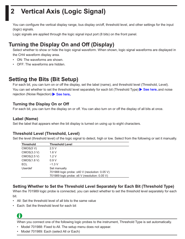
Threshold setting: Preset CMOS (5V/3.3V/2.5V/1.8V), ECL and other standard thresholds, support user-defined, 701988 probe threshold range ± 40V, 701989 probe ± 6V.
Noise suppression: The 701989 probe can be set with a hysteresis of approximately 100mV or 250mV, while the 701988 probe has a fixed hysteresis of 80mV.
Bus display: Supports Bit0-Bit7 combination as bus signal, can choose binary (Bin) or hexadecimal (Hex) display, custom label (up to 8 characters).
Status display: Based on the sampling logic signal status of the clock source (CH1-CH3, LOGIC), it supports clock polarity and detection level settings.
2. Horizontal axis setting (timeline)
Time scale: adjustable through TIME/DIV knob, supports Roll Mode, suitable for observing low-frequency or slowly changing signals. At this time, the waveform flows from right to left without relying on triggering updates.
Sampling rate calculation: The formula is "Sampling rate=Record length/(time scale x 10 grids)", with a record length range of 1.25 kpoints to 1 Gpoints (depending on memory options), and different record lengths correspond to different historical waveform storage quantities.
3. Trigger function
(1) Trigger mode
Pattern description
If triggered within Auto timeout (approximately 100ms or 10 grid times, whichever is greater), the waveform will be updated. Otherwise, it will be automatically updated and supports scrolling mode
Auto Level trigger logic is similar to Auto, automatically adjusting the trigger level to the center value of the trigger source amplitude when there is no trigger (only CH1-CH4 is valid)
Normal updates waveform only when triggering conditions are met
After N Single meets the triggering conditions, continuously collect the specified number of waveforms, and display them after completion
Update the waveform once and stop collecting after triggering Single
(2) Trigger type
EDGE (Edge Triggering): Based on a single trigger source for rising/falling/dual edge triggering, it supports settings such as trigger level, slope, delay, and hold time.
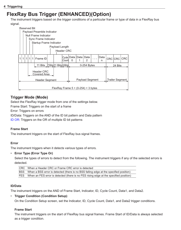
Enhanced Trigger: Contains multiple complex trigger types, such as edge or trigger, mode trigger, pulse width trigger (based on the relationship between pulse width and reference time), rise/fall time trigger, timeout trigger, window trigger, serial bus trigger (FlexRay/CAN FD/LIN/CXPI, mostly option functions), TV trigger (NTSC/PAL/SDTV/HDTV, etc.).
Trigger combination: Supports triggering A (EDGE/ENHANCED) and triggering B (B TRIG) combinations, such as A delaying B (detecting B triggering after a specified time after A triggering), A to B (N times) (detecting B triggering N times after A triggering).
(3) Key trigger parameters
Trigger level: Analog signal range ± 8 grids (resolution 0.01 grids), logic signal varies with probe model (701988 ± 40V, 701989 ± 6V).
Noise suppression: Analog signals support 0.3/0.5/1 grid hysteresis, and logic signals have different hysteresis options depending on the probe model.
Trigger delay: Range - (post trigger time) to 10 seconds, supports delay cancellation (whether to apply delay to time measurement).
4. Waveform acquisition
Acquisition modes: Normal (no processing display), Envelope (display maximum/minimum value pairs to avoid aliasing), Average (multiple acquisition average denoising, supports exponential/linear averaging, average frequency 2-1024).
High resolution mode: After activation, the effective bit count is extended to 16 bits through digital and bandwidth filtering (not applicable to logical signals).
Sampling modes: real-time sampling (maximum 2.5 GS/s), interpolation mode (sinx/x interpolation, suitable for single signal), repeated sampling (random sampling, suitable for repeated signals, equivalent sampling rate up to 250 GS/s).
Acquisition control: RUN/STOP (continuous acquisition/stop), SINGLE (single acquisition), supporting record length settings (affecting acquisition memory usage and historical waveform count).
5. Display function
Window types: including main window (Main), zoom window (Zoom1/Zoom 2), XY window (XY1/XY2), FFT window, trend/histogram window, supporting multi window segmentation (Single/Dual/Triad/Quad formats, etc.).
Display settings: Supports waveform interpolation (OFF/Sine/Linear/Pulse), grid type (point grid/line grid/frame/crosshair), waveform intensity (1-64 levels), cumulative display (displays waveform frequency by intensity/color, cumulative time 100ms-100s or infinite).
XY waveform display: Map two signals to the X-axis and Y-axis respectively, observe signal correlation, support cursor measurement and area calculation (such as safe working area SOA analysis).
6. Data processing and analysis
(1) Calculation and reference waveform
Calculation mode: Supports Math (based on source waveform calculation) and Ref (displaying reference waveform), with calculation sources available from CH1-CH4 and Math1-Math3. Supports addition, subtraction, multiplication, division, filtering, integration, counting, and other operations, with user-defined calculations (option function, supports 128 character expressions).
Reference waveform: It can load screen display waveforms or historical saved waveforms, and supports vertical position adjustment and measurement analysis.
(2) FFT analysis
Function enabled: Supports FFT1/FFT2, allows selection of analysis sources (CH1-CH4, Math1-Math4), and sets spectrum types (power spectrum, linear spectrum, etc., depending on whether there are user-defined options).
Parameter settings: time window (rectangle/Hanning/Flattop), FFT point count (1.25k-1.25M), analysis range (Main/Zoom1/Zoom2), scale settings (automatic/manual), supports cursor measurement and peak detection.
(3) Cursor measurement
Cursor mode: Δ T (time difference), Δ V (voltage difference), Δ T&Δ V (time voltage combination), Marker (4 marker points), Angle (angle measurement), supports multi-channel measurement (CH1-CH4, LOGIC, Math1-Math4).
Measurement items: time (T1/T2/Δ T/1/Δ T), voltage (V1/V2/Δ V), angle (D1/D2/Δ D), supports cursor jumping (such as jumping to the center of the zoom window).
(4) Automatic parameter measurement
Measurement items: voltage parameters (maximum/minimum/peak to peak/effective value, etc.), time parameters (frequency/cycle/pulse width/duty cycle, etc.), delay measurement (multi-channel delay), supporting statistical analysis (maximum/minimum/average/standard deviation/count).
Measurement settings: Select the measurement window (Main/Zoom1/Zoom2), measurement time period (T Range1/T Range2), reference level (percentage or absolute value), and support cycle mode (measured by signal cycle).
(5) Waveform Search and Serial Bus Analysis
Waveform search: supports search types such as edge, mode, pulse width, timeout, etc., sets search sources and conditions (such as level, polarity, time range), displays detection results, and scales positioning.
Serial bus analysis: Supports FlexRay/CAN/CAN FD/LIN/CXPI/SENT/PSI5 Airbag/UART/I2C/SPI buses (mostly options), can decode frame/field information, display results in lists, trend analysis and search, supports symbol display (requires loading. sbl files).
(6) Histogram display
Function enabled: Supports Historam1/Historam2, select the source waveform (CH1-CH4, Math1-Math4) and statistical axis (vertical/horizontal), and set the statistical range (Main/Zoom1/Zoom2).
Measurement items: peak value, maximum value, minimum value, mean value, standard deviation, median, proportion within the range of ± 1 σ/± 2 σ/± 3 σ, supporting cursor measurement.
(7) Power analysis (option function)
Switching Loss Analysis (SW Loss): measures the total loss and switching loss of the device, supports different loss types (U × I, RDS (on) × I ², VCE (sat) × I), and sets voltage/current levels and reference levels.
Safe working area analysis (SOA): X-axis voltage, Y-axis current, plot device operating range, evaluate whether it is within the safe area.
Harmonic analysis: Complies with IEC standards, analyzes up to the 40th harmonic, supports Class A-D classification, calculates harmonic current and compares it with limit values, and displays the results in a list and bar chart.
Joule integral (I ² t): Joule integral for measuring surge current, used for fuse evaluation, supporting waveform display and statistical analysis.
Power measurement: Simultaneously measure the power of two circuits, calculate voltage/current/power parameters (active/reactive/apparent power, power factor, etc.), support probe de skewing and statistical analysis.
7. Historical waveform management
Display mode: Supports single waveform (One), all overlay (All), and accumulate display. It can highlight the specified record number waveform and set the display range (Start/End No.).
Search function: Based on rectangular area, waveform area, polygon area or parameter setting search conditions, supports AND/OR logic, and displays a list of detected waveforms and timestamps.
Playback function: Play back historical waveforms at a specified speed (x1/60 to x10), supporting playback starting from the earliest/latest waveform.
8. Data storage and output
(1) Printing and screen saving
Output target: Built in printer (option), USB printer, network printer, file (PNG/BMP/JPEG format), supports simultaneous output of multiple targets (Multi mode).
Print settings: Print mode (with/without menu), color (color/black and white/grayscale), whether to include setting information, file saving supports automatic naming (serial number/date) and custom file name.
(2) Data saving and loading
Save data types: waveform data (binary/ASCII/ASCII with time information), set data (saved to file or internal memory # 1- # 3), screen image, waveform area data, snapshot data, automatic measurement data, serial bus analysis results, FFT data, histogram data, timestamp list.
Storage devices: internal storage (Flash_Sem), USB storage devices, network drives, supporting file renaming, copying, protection settings, loading data supports waveform, settings, waveform area and other types.
9. Other functions
System settings: AUTO SETUP, DEFILT SETUP, SNAP SHOT to save current waveform, Calibration, Remote Control, system configuration (such as touch screen settings).
Network functions: Supports TCP/IP, FTP server, email sending (sending email notifications when triggered), network drive, network printer, SNTP time synchronization.
Synchronization operation (DLMsync, option): Supports multiple oscilloscopes to work synchronously, expand channels, or increase sampling rates.
Precautions
Safe operation: In DC50 coupling mode, the input impedance is 50 Ω and the maximum input voltage is small, so caution should be exercised during operation; The demagnetization and zeroing of the current probe require disconnecting the conductor to avoid damaging the equipment.
Performance limitations: Long record lengths may result in slower calculation and measurement speeds; Partial functions (such as serial bus triggering and user-defined calculations) are optional and require confirmation of instrument configuration.
Data management: When automatically naming files, attention should be paid to the storage device format (FAT16/FAT32/exFAT) to limit the number of files and avoid duplicate file names causing save failures.
Software compatibility: The Yokogawa IS8000 software can be used to analyze waveforms on a PC, which needs to be obtained through the official website; CANdb files need to be converted to. sbl files in order to be used for symbol display.
- YOKOGAWA
- Reliance
- ADVANCED
- SEW
- ProSoft
- WATLOW
- Kongsberg
- FANUC
- VSD
- DCS
- PLC
- man-machine
- Covid-19
- Energy and Gender
- Energy Access
- Renewable Integration
- Energy Subsidies
- Energy and Water
- Net zero emission
- Energy Security
- Critical Minerals
- A-B
- petroleum
- Mine scale
- Sewage treatment
- cement
- architecture
- Industrial information
- New energy
- Automobile market
- electricity
- Construction site
- HIMA
- ABB
- Rockwell
- Schneider Modicon
- Siemens
- xYCOM
- Yaskawa
- Woodward
- BOSCH Rexroth
- MOOG
- General Electric
- American NI
- Rolls-Royce
- CTI
- Honeywell
- EMERSON
- MAN
- GE
- TRICONEX
- Control Wave
- ALSTOM
- AMAT
- STUDER
- KONGSBERG
- MOTOROLA
- DANAHER MOTION
- Bentley
- Galil
- EATON
- MOLEX
- Triconex
- DEIF
- B&W
- ZYGO
- Aerotech
- DANFOSS
- KOLLMORGEN
- Beijer
- Endress+Hauser
- schneider
- Foxboro
- KB
- REXROTH
- YAMAHA
- Johnson
- Westinghouse
- WAGO
- TOSHIBA
- TEKTRONIX
- BENDER
- BMCM
- SMC
- HITACHI
- HIRSCHMANN
- XP POWER
- Baldor
- Meggitt
- SHINKAWA
- Other Brands
- UniOP
- KUKA
- IBA
- Beckhoff
-
LTI SC52.0040.0012.0000.0 - Servo Drive
-
Lti SC52.0040.0012.0000.0 - Servo Drive
-
Milton Industries LTI Tool By Milton LT1240 - 1/2" Drive Lugnut Remover
-
LTi Drives SO84.200.P030.0000.0-W - Servo Spindle Drive
-
LTI DRIVES LSP08-035-320-30-B0R1PY170 - Servo Motor
-
LTI DRIVES SE84.200.SC00.0001.0-W - Servo Drive
-
Lust CDE34.005.W2.2 - Lti Drives Controller
-
LTi SO84.012.0030.0011.2 - ServoOne Servo Drive
-
LTi Drives SO CM-P.0010.11.00.0 - Servo Drive Controller
-
LTi CDE34.017.W3.0 - Servo Drive
-
LTI Drives CDB32.004, C2.0,SH - Positioning Controller
-
LUST CM-CAN1 - LTi DRIVES Communication Module
-
LTi SO84.012.1030.0000.2 - Servo Drive
-
LTI MOOG CDE54.044 - PITCHMASTER FREQUENCY CONVERTER 181-01019
-
MOOG LTI 181-01019 CDE54.044 - PITCHMASTER FREQUENCY CONVERTER
-
Lust LTi Drives CDE34.010,D2.0 - Servo Drive Controller
-
LTI SO84.032.0003.0101.2 - Servo Drive
-
Seagate 9CC132-302 Harris LTI-CS IRT-34-0021-01 - Hard Drive 160GB
-
LTI SO84.032.0003.0001.2 - Servo Drive
-
LTI SO24.007.0070.0000.1 - SERVO CONTROLLER
-
LTi drive CDA32.003.C3.0.H05-01.PC1 - Servo Drive
-
LTI SO84.016.0030.0000.2 - SERVO CONTROLLER
-
LUST LTI CD A34.008,W1.4, BR - SERVO DRIVE
-
MOOG LTI 181-01019 CDE54.044 - PITCHMASTER FREQUENCY CONVERTER
-
LTI MOOG 181-01019 - PITCH Master Servo Drive CDE54.044
-
LTI SERVO ONE SO84.045.0030.0001.2-W - Drive
-
LUST LTi SO84.032.0040.0000.2 - SERVO ONE DRIVE
-
LTi Drives LSH-074-2-30-3 20/T1,G6.1M - SERVO MOTOR
-
LTI SO84.016.0000.0101.2 - servo drive
-
LTI SA54.0550.0033.0000.0 - Servo Drive
-
LTI SA54.0550.0033.0000.0 - Servo Drive
-
LTI LT 4850 - 3/8" Drive 3-Pc Twist Socket Transmission Drain Plug Removal System
-
LTI Tools LT4400-30 Lock Technology - 3/4" Twist Socket 1/2" Drive Lugnut Remover
-
LTI Tools LT-1400C - 1/2 Drive Wheel Torque Extension Tool
-
LTI Tools LT1250 - 1/2" Drive Dual Sided Socket Lug Nut Remover Tool
-
LTI SO84.032.0003.0101.2 - Servo Drive
-
LTI MOOG 181-01019 - PITCH Master Servo Drive CDE54.044
-
MOOG LTI 181-01019 CDE54.044 - PITCHMASTER FREQUENCY CONVERTER
-
MOOG LTI 181-01019 CDE54.044 - PITCHMASTER FREQUENCY CONVERTER
-
MOOG LTI 181-01019 CDE54.044 - PITCHMASTER FREQUENCY CONVERTER
-
LTI SA54.0550.0033.0000.0 - Servo Drive
-
LTI Tools LT-4800 - 7 Piece Twist Socket 3/8" Drive Oil Drain Plug Removal Set
-
LTI SA54.0550.0033.0000.0 - Servo Drive
-
LTI Drive SO24.007.00300000.0 - Servo Drive
-
LTI TOOLS LTI 1400-I - Drive Wheel Torque Extension
-
LTI Tools LT4400-3 - 3/4" 19mm Twist Socket 1/2" Drive Lugnut
-
LTI TOOLS LTI 1400-BB - Drive Wheel Torque Extension
-
LTI SO84.032.0003.0101.2 - Servo Drive
-
LTI Tools LT-4512 - 3/8" Drive 12mm Twist Socket
-
LTI MOTION Luster SO84.032.0003.0001.2 - Servo Drive
-
LTI Tool By Milton LT1600P - 1" Drive Torx Stick
-
LTI Lust VF1424L,HF,OP2,S56 - Variable Frequency Drive
-
LUST CDA32.004,C1.4,H08,B0 - SERVO DFRIVE CM-CAN1 Module
-
LTI SO84.045.0002.0001.2-W - Drive
-
LTI Lust VF1404M,C9,PT1,BR1 - Inverter Type VF1404M
-
LTI SA54.0550.0033.0000.0 - Servo Drive
-
LTI Tools LT-1400C - 1/2" Drive Wheel Torque Extension
-
Lust LTI DRiVES CDA32.006, C3.0, H09 - Variateur De Fr茅quence Frequency Inverter
-
LTI MOOG CDE54.044 - PITCH master SERVO DRIVE
-
LTI MOOG CDE54.044 - PITCH master SERVO DRIVE
-
LTI SO84.143.0020.0101.2-W - servo drive
-
LTI MOTION SC34.0200.0011.0000.0 - Servo drives
-
LTI SO84.032.0003.0001.2 - Servo Drive
-
LTI DRIVES GmbH MS100 - Assembly Set Mounting Kit
-
LTI SO84.032.0003.0001.2 - Servo Drive
-
LTI SO84.032.0003.0001.2 - Servo Drive
-
LTI MOTION SO84.032.0003.0101.2 - servo drive
-
LTI SO84.032.0003.0101.2 - Servo Drive
-
LTI MOOG CDE54.044 - PITCH master SERVO DRIVE
-
LTI MOTION CDE32.004.C2.4 - Servo drives
-
LTI CDD34.032锛學x.x锛孊R锛孭C1 - Servo Drive
-
Lust LTI DRiVES CDA32.006, C3.0, H09 - Inversor De Frecuencia Frequency Inverter
-
Lust SO84.008.0030.1000.0 - Servo One LTi Drive
-
LTI MOTION SO84.032.0003.0101.2 - Servo drives
-
LUST LTi CDA32.004,C1.4 - SERVO DRIVE
-
LTI MOOG CDE54.044 - PITCH Master SERVO DRIVE
-
LTI KEBA CDB32.004 C2.7, SH - PN: 08673530 Frequency Inverter
-
LTI Tools LT-1400C - 1/2" Drive Wheel Torque Extension
-
LTI LT1400-E - 1/2" Drive Wheel Torque Extension
-
LTI MOOG 181-01019 - PITCH master SERVO DRIVE CDE54.044
-
LTI LSN-097-0510-30-560/T1 - Actuator Motor
-
LTI Tools LT 4800 - 7 Piece 3/8" Drive Twist Socket Oil Drain Plug Removal System
-
LTI DRIVES GmbH MS100 - MONTAGESET Assembly Set Mounting Kit
-
Lti SC52.0040.0012.0000.0 - Servo Drive
-
LTI DRIVES GmbH MS100 - Juego De Montaje Assembly Set Mounting Kit
-
LTi DSM4-14.2-21R83-200 - Drives servomoteur Servo Motor
-
MOOG CDE 54.044.GDA - Pitch Master Industrielle Turbine Lti Drive
-
LTI SO24.004.0030.1000.0 - Servo Drive Controller
-
Lti MOOG CDE54.044 - Pitch Master Servo Drive
-
Lust LTI DRiVES CDA32.006, C3.0, H09 - Inverter
-
LTI MOTION GMBH CDB34.006,W3.0,PC1,H39 - Frequency inverter
-
LTI SO84.032.0003.0001.2 - Servo Drive
-
MOOG CDE 54.044.D - Pitch Master Industrielle Turbine Lti Drive
-
LTI TOOLS LT-1460 - 1/2" DRIVE WHEEL TORQUE EXTENSION KIT 5 PIECE SET
-
Lust Cdb32.003, C2.4 - Lti Drives Servoregulador Frecuencia Servo Controller Inverter
-
Lust LTI DRIVES CDA32.006, C3.0, H09 - Frequency Inverter
-
Lust Lti SO82.004.0030.0000.2 - Servo Drive
-
LTI MOTION SC34.0200.0011.0000.0-SL - Servo drives
-
LTI MOTION SA54.0075.0033.0000.0 - Servo drives
-
LTI MOTION SC32.0075.1011.0000.0 - Servo drives
-
LTI Servo-One Junior SO22.006.0080.1000.0 - Servo Controller Servoregler
-
LUST CDA32.004, C1.4, H08, B0 - Servo Drive & LTI CM-CAN1 Module
-
LTI DRIVES LSP08-035-320-30-B0R1PY170 - Servo Motor
-
LUST LTI CDA32.004,C1.4.H08.B0 - SERVO CONTROLLER DRIVES
-
LUST LTi DRiVES CDS44.072LC1.2 - Servo Drive
-
Lti Servo-One Junior SO22.006.0082.1000.0 - Servo Controller Servoregler
-
LUST CDA32.008,C2.0,HF - Lti DRIVES Spindle Drive Inverter
-
LTI SO22.003.0082.0000.0 - Servo Drives One junior Servo Controller Servoregler
-
Lust Lti Drives CM-CAN1 - Communication Module
-
LUST Lti Drives Vf1202s, G8, I6 - Frequency Inverter Drive
-
LTI DRIVES BR-090.03.540.UR.H38 - Bremswiderstand Brake Resistor
-
LTi DRIVES PM-E40.2DRA054P - Wind Turbine Pitch Control Inverter
-
LTi Drives GmbH br-110.01.540-UR - Brake Resistor
-
LTI Drives LSN-097-0960-30-0560/T1,S4,B - Servo Motor
-
LUST CDA34.006.C2.0 - LTI Drives Servoregler
-
LUST LTI DRIVES SERVO ONE JUNIOR SO24.002.0020.0000.1 - Servo Drive Controller
-
LTI MOTION SO84.032.0003.0001.2 - Servo drives
-
LTI DDTD750V2-120 - IBOP ACTUATOR CYLINDER FOR TOP DRIVE
-
LTI CDE32.004, C2.4 - SERVO DRIVE
-
LUST LTI DRIVES CDD34.017 W3.4PC1 - Servo Drive Controller
-
LTI CDA3208,C3,0,HF - AC SERVO DRIVE
-
LUST LTI DRIVES LSH-074-3-30-560/T1,G6.1S - SERVO MOTOR
-
LUST Lti CDB32.004.C2.4.SH - AC Servo Drive
-
LTi CDA32.006, C3.0, H09 - Servo Drive
-
LTI SO22.003.0010.0000.0 - Servo Drive Servo one junior Servoregler Controller
-
LTi Drives DSM4-14.2-21R83-200 - Servo Motor
-
LUST Lti Drives Lsh-097-1-30-560/T1, 1R - Servomotor
-
LTI 1237 - 7 Piece 1/2" Drive Flip Socket Set

K-JIANG

Add: Jimei North Road, Jimei District, Xiamen, Fujian, China
Tell:+86-15305925923