
K-WANG


YOKOGAWA SC4AJ Conductivity Sensor
YOKOGAWA SC4AJ Conductivity Sensor
Equipment foundation and adaptation system
1. Core positioning and application scenarios
SC4AJ is a compact sensor designed specifically for low conductivity solutions, suitable for industries such as semiconductors, power, and pharmaceuticals that require high purity (such as ultrapure water detection). It needs to be paired with a specific analyzer/converter to form a complete detection system. The compatible equipment and corresponding manual information are as follows:
Corresponding manual number for supporting equipment type
FLXA202, FLXA21 2-wire analyzer IM 12A01A02-01E
FLXA402 4-wire converter IM 12A01F01-02EN, IM 12A01F03-01EN, etc
SC450G Conductivity Converter IM 12D08N05-01E
SA11 Smart Adapter IM 12A06S01-00EN-P
2. Equipment core classification and parameters
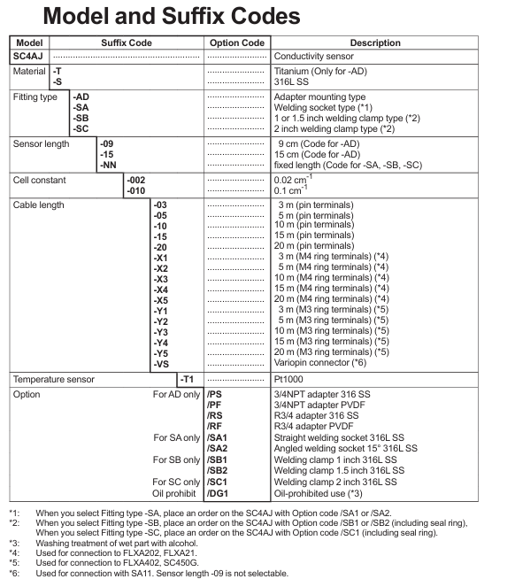
SC4AJ is classified into models based on electrode material, installation method, and battery constant. The core differences focus on adaptation scenarios and measurement ranges. The specific classifications are as follows:
Classification dimensions, specific types, key parameters/characteristics
Electrode material titanium (- T) is only suitable for adapter installation type (- AD), with strong corrosion resistance
316L stainless steel material (- S) is compatible with all installation methods and has strong universality
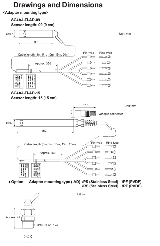
Installation method: Adapter installation type (- AD) with 3/4NPT or R3/4 adapter (stainless steel/PVDF material), sensor length 9cm/15cm
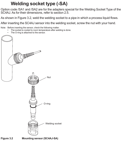
Welding socket type (- SA) requires straight type (/SA1) or 15 ° angle type (/SA2) welding socket, with fixed sensor length
Welding clip type (- SB/- SC) - SB compatible 1/1.5 inch clip (/SB1//SB2), - SC compatible 2-inch clip (/SC1), including sealing ring
Battery constant 0.02 cm ⁻¹ (-002) measurement range 0-0.5 μ S/cm to 0-200 μ S/cm, suitable for extremely low conductivity solutions
0.1 cm ⁻¹ (-010) measurement range 0-5 μ S/cm to 1 mS/cm, suitable for low conductivity solutions
Cable terminal pin type/M4 ring type/M3 ring type/Variopin pin type compatible with multiple devices; M4 ring adapter FLXA202/FLXA21; M3 ring adapter FLXA402/SC450G; Variopin compatible with SA11
3. General technical specifications
Temperature and pressure: The electrode has a conventional temperature of 0-110 ℃ (can be steam sterilized at 135 ℃ for 30 minutes) and a pressure of 0-1 MPa; The tolerance range of the bracket varies with the material (stainless steel 316L has higher temperature resistance, PVDF has lower temperature resistance, please refer to the temperature pressure curve for details)
Contact fluid material: main body (316L stainless steel/titanium), O-ring (FKM fluororubber, EPDM EPDM EPDM), adapter (PVDF or 316L stainless steel)
Temperature compensation: Built in Pt1000 temperature sensor to calibrate the effect of temperature on conductivity
Protection restriction: The sensor mold and metal joint are not waterproof and cannot be immersed in process water
Safety regulations and usage restrictions
1. Core security principles
Prohibited unauthorized operation: Only use according to the instructions in the manual, unauthorized modification of the device will result in loss of protective function; Repairs require Yokogawa certified spare parts, unauthorized modifications are prohibited
Static electricity and explosion prevention: The flow of ultrapure water in plastic pipes may generate static electricity, and it is necessary to avoid the sensor conducting static electricity and damaging the converter circuit; Must comply with explosion-proof standards such as IEC 60079-11 and GB 3836.4-2010 (TIIS certified models cannot be connected), and if necessary, affix a "simple equipment" label
Temperature limit: The maximum process temperature needs to be determined based on the supporting analyzer (FLXA202/FLXA21) and temperature level (T1-T6). For example, under T6 level, the maximum process temperature at 40 ℃/60 ℃ ambient temperature is 49 ℃; At T5 level, the ambient temperature is 95 ℃ at 40 ℃ (note that the upper limit of T5 level is 100 ℃)
2. Manual usage guidelines
It needs to be handed over to the end user and properly stored, and unauthorized copying/dissemination is prohibited; Yokogawa reserves the right to improve manuals and equipment without prior notice
The manual only describes the device functions and does not guarantee adaptation to specific user scenarios; The equipment is provided as is, and Yokogawa is not responsible for unforeseeable direct/indirect losses
Installation and Wiring Guide
1. Core installation requirements
Installation principle: Ensure uniform composition and no dead zone when the solution flows through the sensor; The sensor needs to be submerged above the outlet to ensure continuous liquid flow between the electrodes; Reserve maintenance space for easy disassembly and release of process pressure; Confirm that the pressure at the installation site is within the tolerance range of the sensor and adapter
Steps for different installation methods:
Adapter installation type (- AD): Assemble in the order of "nut → adapter support (stainless steel adapter) → adapter → sealing ring → sensor body", tighten the nut with a torque of about 190 N · m (tighten with fingers and then use a wrench to tighten 1.25 turns)
Welding socket type (- SA): First weld the welding socket to the process pipeline (cool to room temperature), insert the sensor into the socket after installing the O-ring, and fix it by hand tightening the nut
Welding clamp type (- SB/- SC): First weld the flange to the pipeline, insert the sensor into the flange after installing the sealing ring, and fix it with a special fixture
2. Wiring requirements
Wiring logic: Connect according to the cable end identification and the terminal number of the analyzer/converter, for example, connect the temperature sensor wire (brown/black/red) to the corresponding temperature terminal, and the electrode wire (green/yellow) to the corresponding electrode terminal; Variopin terminal (- VS) needs to be connected to SA11 adapter
Cable specifications: Cable length 3-20m (selected according to the order), avoid contact with high-temperature components, and ensure that the insulation resistance meets the requirements after wiring (such as 1000-1137 Ω between terminals 11-12 and>100 M Ω between terminals 11-13)
Operation and maintenance process
1. Preparation and calibration before operation
Pre operation inspection: Confirm that the cable connection is correct, the solution is leak free, the temperature/pressure is within the range, and the solution level reaches the outlet height
Battery constant setting: The factory calibrated battery constant on the cable label needs to be input into the matching analyzer/converter (refer to the corresponding equipment manual for operation steps)
Calibration requirements: Use a standard solution with known conductivity for calibration (the conductivity of the standard solution should be close to that of the test liquid). Before calibration, the sensor should be equilibrated with the temperature of the solution, and the temperature should be measured using a calibration thermometer
2. Core maintenance operations
(1) Sensor cleaning
Choose the cleaning method based on the type of pollutant, and prohibit mixing hydrochloric acid with chlorine containing solvents (to avoid producing toxic chlorine gas):
Scale and hydroxides: Clean with 5-10% hydrochloric acid solution
Organic dirt (oil, grease): Wipe with ethanol or acetone
Algae/bacteria: Clean with chlorine containing solution (household bleach)
Conventional pollution: cleaning with hot water and household detergent
After cleaning, visually inspect the sensor for any damage or deformation
(2) Abnormal judgment
After the sensor dries, measure the resistance between the terminals with a digital multimeter. If it exceeds the following range, it needs to be replaced:
Terminal combination (non VS) Variopin terminal combination (- VS) standard resistance at room temperature
11-12 E-F 1000-1137 Ω
11-13, 13-15, 12-15 E-C, C-A, F-A>100 M Ω
13-14, 15-16 C-D, A-B < 10 Ω
3. Spare parts information
Core spare parts need to be matched according to the installation method, and common spare parts are as follows:
Type description corresponding to spare part number
K9670MA SA (non VS) O-ring
K9670VY SA (- VS) O-ring set
K9670MK-SB sealing ring (compatible/SB1//SB2)
K9670MP SC sealing ring (compatible/SC1)
K9670MT/MU-AD 3/4NPT stainless steel/PVDF adapter
K9670ME/MD-SA straight/angle welding socket and installation nut
- YOKOGAWA
- Reliance
- ADVANCED
- SEW
- ProSoft
- WATLOW
- Kongsberg
- FANUC
- VSD
- DCS
- PLC
- man-machine
- Covid-19
- Energy and Gender
- Energy Access
- Renewable Integration
- Energy Subsidies
- Energy and Water
- Net zero emission
- Energy Security
- Critical Minerals
- A-B
- petroleum
- Mine scale
- Sewage treatment
- cement
- architecture
- Industrial information
- New energy
- Automobile market
- electricity
- Construction site
- HIMA
- ABB
- Rockwell
- Schneider Modicon
- Siemens
- xYCOM
- Yaskawa
- Woodward
- BOSCH Rexroth
- MOOG
- General Electric
- American NI
- Rolls-Royce
- CTI
- Honeywell
- EMERSON
- MAN
- GE
- TRICONEX
- Control Wave
- ALSTOM
- AMAT
- STUDER
- KONGSBERG
- MOTOROLA
- DANAHER MOTION
- Bentley
- Galil
- EATON
- MOLEX
- Triconex
- DEIF
- B&W
- ZYGO
- Aerotech
- DANFOSS
- KOLLMORGEN
- Beijer
- Endress+Hauser
- schneider
- Foxboro
- KB
- REXROTH
- YAMAHA
- Johnson
- Westinghouse
- WAGO
- TOSHIBA
- TEKTRONIX
- BENDER
- BMCM
- SMC
- HITACHI
- HIRSCHMANN
- XP POWER
- Baldor
- Meggitt
- SHINKAWA
- Other Brands
- UniOP
- KUKA
- IBA
- Beckhoff
-
LTI SC52.0040.0012.0000.0 - Servo Drive
-
Lti SC52.0040.0012.0000.0 - Servo Drive
-
Milton Industries LTI Tool By Milton LT1240 - 1/2" Drive Lugnut Remover
-
LTi Drives SO84.200.P030.0000.0-W - Servo Spindle Drive
-
LTI DRIVES LSP08-035-320-30-B0R1PY170 - Servo Motor
-
LTI DRIVES SE84.200.SC00.0001.0-W - Servo Drive
-
Lust CDE34.005.W2.2 - Lti Drives Controller
-
LTi SO84.012.0030.0011.2 - ServoOne Servo Drive
-
LTi Drives SO CM-P.0010.11.00.0 - Servo Drive Controller
-
LTi CDE34.017.W3.0 - Servo Drive
-
LTI Drives CDB32.004, C2.0,SH - Positioning Controller
-
LUST CM-CAN1 - LTi DRIVES Communication Module
-
LTi SO84.012.1030.0000.2 - Servo Drive
-
LTI MOOG CDE54.044 - PITCHMASTER FREQUENCY CONVERTER 181-01019
-
MOOG LTI 181-01019 CDE54.044 - PITCHMASTER FREQUENCY CONVERTER
-
Lust LTi Drives CDE34.010,D2.0 - Servo Drive Controller
-
LTI SO84.032.0003.0101.2 - Servo Drive
-
Seagate 9CC132-302 Harris LTI-CS IRT-34-0021-01 - Hard Drive 160GB
-
LTI SO84.032.0003.0001.2 - Servo Drive
-
LTI SO24.007.0070.0000.1 - SERVO CONTROLLER
-
LTi drive CDA32.003.C3.0.H05-01.PC1 - Servo Drive
-
LTI SO84.016.0030.0000.2 - SERVO CONTROLLER
-
LUST LTI CD A34.008,W1.4, BR - SERVO DRIVE
-
MOOG LTI 181-01019 CDE54.044 - PITCHMASTER FREQUENCY CONVERTER
-
LTI MOOG 181-01019 - PITCH Master Servo Drive CDE54.044
-
LTI SERVO ONE SO84.045.0030.0001.2-W - Drive
-
LUST LTi SO84.032.0040.0000.2 - SERVO ONE DRIVE
-
LTi Drives LSH-074-2-30-3 20/T1,G6.1M - SERVO MOTOR
-
LTI SO84.016.0000.0101.2 - servo drive
-
LTI SA54.0550.0033.0000.0 - Servo Drive
-
LTI SA54.0550.0033.0000.0 - Servo Drive
-
LTI LT 4850 - 3/8" Drive 3-Pc Twist Socket Transmission Drain Plug Removal System
-
LTI Tools LT4400-30 Lock Technology - 3/4" Twist Socket 1/2" Drive Lugnut Remover
-
LTI Tools LT-1400C - 1/2 Drive Wheel Torque Extension Tool
-
LTI Tools LT1250 - 1/2" Drive Dual Sided Socket Lug Nut Remover Tool
-
LTI SO84.032.0003.0101.2 - Servo Drive
-
LTI MOOG 181-01019 - PITCH Master Servo Drive CDE54.044
-
MOOG LTI 181-01019 CDE54.044 - PITCHMASTER FREQUENCY CONVERTER
-
MOOG LTI 181-01019 CDE54.044 - PITCHMASTER FREQUENCY CONVERTER
-
MOOG LTI 181-01019 CDE54.044 - PITCHMASTER FREQUENCY CONVERTER
-
LTI SA54.0550.0033.0000.0 - Servo Drive
-
LTI Tools LT-4800 - 7 Piece Twist Socket 3/8" Drive Oil Drain Plug Removal Set
-
LTI SA54.0550.0033.0000.0 - Servo Drive
-
LTI Drive SO24.007.00300000.0 - Servo Drive
-
LTI TOOLS LTI 1400-I - Drive Wheel Torque Extension
-
LTI Tools LT4400-3 - 3/4" 19mm Twist Socket 1/2" Drive Lugnut
-
LTI TOOLS LTI 1400-BB - Drive Wheel Torque Extension
-
LTI SO84.032.0003.0101.2 - Servo Drive
-
LTI Tools LT-4512 - 3/8" Drive 12mm Twist Socket
-
LTI MOTION Luster SO84.032.0003.0001.2 - Servo Drive
-
LTI Tool By Milton LT1600P - 1" Drive Torx Stick
-
LTI Lust VF1424L,HF,OP2,S56 - Variable Frequency Drive
-
LUST CDA32.004,C1.4,H08,B0 - SERVO DFRIVE CM-CAN1 Module
-
LTI SO84.045.0002.0001.2-W - Drive
-
LTI Lust VF1404M,C9,PT1,BR1 - Inverter Type VF1404M
-
LTI SA54.0550.0033.0000.0 - Servo Drive
-
LTI Tools LT-1400C - 1/2" Drive Wheel Torque Extension
-
Lust LTI DRiVES CDA32.006, C3.0, H09 - Variateur De Fr茅quence Frequency Inverter
-
LTI MOOG CDE54.044 - PITCH master SERVO DRIVE
-
LTI MOOG CDE54.044 - PITCH master SERVO DRIVE
-
LTI SO84.143.0020.0101.2-W - servo drive
-
LTI MOTION SC34.0200.0011.0000.0 - Servo drives
-
LTI SO84.032.0003.0001.2 - Servo Drive
-
LTI DRIVES GmbH MS100 - Assembly Set Mounting Kit
-
LTI SO84.032.0003.0001.2 - Servo Drive
-
LTI SO84.032.0003.0001.2 - Servo Drive
-
LTI MOTION SO84.032.0003.0101.2 - servo drive
-
LTI SO84.032.0003.0101.2 - Servo Drive
-
LTI MOOG CDE54.044 - PITCH master SERVO DRIVE
-
LTI MOTION CDE32.004.C2.4 - Servo drives
-
LTI CDD34.032锛學x.x锛孊R锛孭C1 - Servo Drive
-
Lust LTI DRiVES CDA32.006, C3.0, H09 - Inversor De Frecuencia Frequency Inverter
-
Lust SO84.008.0030.1000.0 - Servo One LTi Drive
-
LTI MOTION SO84.032.0003.0101.2 - Servo drives
-
LUST LTi CDA32.004,C1.4 - SERVO DRIVE
-
LTI MOOG CDE54.044 - PITCH Master SERVO DRIVE
-
LTI KEBA CDB32.004 C2.7, SH - PN: 08673530 Frequency Inverter
-
LTI Tools LT-1400C - 1/2" Drive Wheel Torque Extension
-
LTI LT1400-E - 1/2" Drive Wheel Torque Extension
-
LTI MOOG 181-01019 - PITCH master SERVO DRIVE CDE54.044
-
LTI LSN-097-0510-30-560/T1 - Actuator Motor
-
LTI Tools LT 4800 - 7 Piece 3/8" Drive Twist Socket Oil Drain Plug Removal System
-
LTI DRIVES GmbH MS100 - MONTAGESET Assembly Set Mounting Kit
-
Lti SC52.0040.0012.0000.0 - Servo Drive
-
LTI DRIVES GmbH MS100 - Juego De Montaje Assembly Set Mounting Kit
-
LTi DSM4-14.2-21R83-200 - Drives servomoteur Servo Motor
-
MOOG CDE 54.044.GDA - Pitch Master Industrielle Turbine Lti Drive
-
LTI SO24.004.0030.1000.0 - Servo Drive Controller
-
Lti MOOG CDE54.044 - Pitch Master Servo Drive
-
Lust LTI DRiVES CDA32.006, C3.0, H09 - Inverter
-
LTI MOTION GMBH CDB34.006,W3.0,PC1,H39 - Frequency inverter
-
LTI SO84.032.0003.0001.2 - Servo Drive
-
MOOG CDE 54.044.D - Pitch Master Industrielle Turbine Lti Drive
-
LTI TOOLS LT-1460 - 1/2" DRIVE WHEEL TORQUE EXTENSION KIT 5 PIECE SET
-
Lust Cdb32.003, C2.4 - Lti Drives Servoregulador Frecuencia Servo Controller Inverter
-
Lust LTI DRIVES CDA32.006, C3.0, H09 - Frequency Inverter
-
Lust Lti SO82.004.0030.0000.2 - Servo Drive
-
LTI MOTION SC34.0200.0011.0000.0-SL - Servo drives
-
LTI MOTION SA54.0075.0033.0000.0 - Servo drives
-
LTI MOTION SC32.0075.1011.0000.0 - Servo drives
-
LTI Servo-One Junior SO22.006.0080.1000.0 - Servo Controller Servoregler
-
LUST CDA32.004, C1.4, H08, B0 - Servo Drive & LTI CM-CAN1 Module
-
LTI DRIVES LSP08-035-320-30-B0R1PY170 - Servo Motor
-
LUST LTI CDA32.004,C1.4.H08.B0 - SERVO CONTROLLER DRIVES
-
LUST LTi DRiVES CDS44.072LC1.2 - Servo Drive
-
Lti Servo-One Junior SO22.006.0082.1000.0 - Servo Controller Servoregler
-
LUST CDA32.008,C2.0,HF - Lti DRIVES Spindle Drive Inverter
-
LTI SO22.003.0082.0000.0 - Servo Drives One junior Servo Controller Servoregler
-
Lust Lti Drives CM-CAN1 - Communication Module
-
LUST Lti Drives Vf1202s, G8, I6 - Frequency Inverter Drive
-
LTI DRIVES BR-090.03.540.UR.H38 - Bremswiderstand Brake Resistor
-
LTi DRIVES PM-E40.2DRA054P - Wind Turbine Pitch Control Inverter
-
LTi Drives GmbH br-110.01.540-UR - Brake Resistor
-
LTI Drives LSN-097-0960-30-0560/T1,S4,B - Servo Motor
-
LUST CDA34.006.C2.0 - LTI Drives Servoregler
-
LUST LTI DRIVES SERVO ONE JUNIOR SO24.002.0020.0000.1 - Servo Drive Controller
-
LTI MOTION SO84.032.0003.0001.2 - Servo drives
-
LTI DDTD750V2-120 - IBOP ACTUATOR CYLINDER FOR TOP DRIVE
-
LTI CDE32.004, C2.4 - SERVO DRIVE
-
LUST LTI DRIVES CDD34.017 W3.4PC1 - Servo Drive Controller
-
LTI CDA3208,C3,0,HF - AC SERVO DRIVE
-
LUST LTI DRIVES LSH-074-3-30-560/T1,G6.1S - SERVO MOTOR
-
LUST Lti CDB32.004.C2.4.SH - AC Servo Drive
-
LTi CDA32.006, C3.0, H09 - Servo Drive
-
LTI SO22.003.0010.0000.0 - Servo Drive Servo one junior Servoregler Controller
-
LTi Drives DSM4-14.2-21R83-200 - Servo Motor
-
LUST Lti Drives Lsh-097-1-30-560/T1, 1R - Servomotor
-
LTI 1237 - 7 Piece 1/2" Drive Flip Socket Set

K-JIANG

Add: Jimei North Road, Jimei District, Xiamen, Fujian, China
Tell:+86-15305925923