
K-WANG


Danaher Motion S200 series high-performance brushless servo drive
Danaher Motion S200 series high-performance brushless servo drive
Product Overview and Model Code
Product Core Positioning
The S200 series is a high-performance compact brushless servo drive launched by Danaher Motion. It is divided into basic models (- VTS) and SynqNet network models (- SRS/- SDS), focusing on "small size and high performance". With an 800Hz speed loop bandwidth, 3-5 kHz current loop bandwidth, and 24 bit high-resolution feedback, it achieves smooth motion and fast start stop, suitable for semiconductor manufacturing, electronic assembly, medical and other scenarios that require high precision and response speed. The product was first released in 2004 and updated to Rev. C version in 2008, adding high-power models S21260 (12/30ARMS) and S22460 (24/48ARMS). Products produced after 2007 comply with the RoHS directive.
Model coding rules
The model consists of "series+current level+voltage type+functional options+interface type", and the core coding dimensions and example analysis are as follows:
Explanation of the meaning of the coding section and key codes
Series Identification Core Product Series S20260(AC,4.5ARMS)、S20360(AC,9ARMS)、S20660(AC,18ARMS)、S20330(DC,9ARMS)
Current level peak current specifications 02 (4.5ARMS), 03 (9ARMS), 06 (18ARMS), 12 (30ARMS), 24 (48ARMS)
Voltage type power supply input type 3 (DC 20-90VDC), 5 (AC 120V double voltage/240V single-phase), 6 (AC 120/240VAC)
Function Options Core Function Configuration - VTS (Basic), - SRS (SynqNet+RJ45 Interface), - SDS (SynqNet+Micro-D Interface)
Core Technical Parameters
Power Supply and Current Parameters
Model Series Power Supply Type Peak Current (ARMS) Continuous Current (ARMS) Peak Power (VA) Continuous Power (W)
S20260 AC 120/240V 4.5 1.5 1400 (1 phase)/1500 (3 phases) 500 (1 phase)/600 (3 phases)
S20360 AC 120/240V 9 3 2600 (1 phase)/3000 (3 phases) 900 (1 phase)/1100 (3 phases)
S20660 AC 120/240V 18 6 5000 (1 phase)/6000 (3 phases) 1500 (1 phase)/2000 (3 phases)
S20330 DC 20-90VDC 9 3 750 250
S20630 DC 20-90VDC 18 6 1500 500
S21260 AC 240V 30 12 8000 (1 phase)/10000 (3 phases) 2500 (1 phase)/4000 (3 phases)
S22460 AC 240V 3-phase 48 24 16000 8000
Control Performance and Feedback Parameters
Control mode: Supports three modes: torque/current, speed, and position. The position mode supports step direction and AquadB command input
Dynamic performance: The maximum stable bandwidth of the speed loop is 800Hz, the current loop width is 3-5kHz, and the position command resolution is<0.001rpm (analog)/0.558rpm (serial)
Feedback resolution: SFD feedback 0.0013 arc minutes per revolution, repeat positioning accuracy<± 0.04 arc minutes RMS
Instruction interface: Analog instruction ± 12.5V, maximum step frequency 1.5MHz, PWM instruction 0.25-250kHz
Protection functions: over temperature, over voltage, under voltage, over current, short circuit, I ² T thermal protection, feedback fault protection
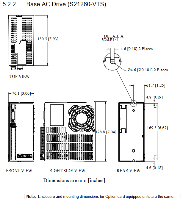
Installation and wiring specifications
Installation Requirements
Installation method: Vertically installed on a conductive grounding surface, remove the paint from the installation area to ensure good grounding
Heat dissipation gap: minimum 12.7mm at the top/bottom (19mm for S21260/S22460), minimum 12.7mm at the sides (19mm for S21260/S22460)
Mechanical dimensions: width 28.7-96.4mm, height 152.4-213mm, depth 100.8-192.4mm, weight 0.4-2.63kg
Environmental restrictions: Operating temperature 0-40 ℃ (50 ℃ requires capacity reduction), storage temperature -35-85 ℃, humidity 10-90% (no condensation), altitude<1500m
Core interface wiring
The manual provides detailed specifications for the wiring definitions of interfaces such as J1 (power supply), J2 (motor), J3 (feedback), J4 (instruction I/O), J5 (serial port), J11/J12 (SynqNet), etc. The core points are:
Power wiring: AC models need to distinguish between control power (C1/C2) and motor power (L1/L2/L3), DC models need to distinguish between+BUS (main power) and+CTRL (control power), and grounding must comply with PE specifications
Motor wiring: The 3-phase motor is connected to the U/V/W phase and needs to match the motor polarity. The motor casing needs to be grounded
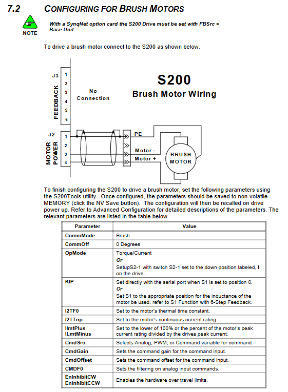
Feedback wiring: SFD feedback uses J3 interface (IEEE1394 style), Hall feedback connects CU/CV/CW pins, incremental encoder supports RS422 differential input
Instruction I/O wiring: Analog instructions support differential input, universal input voltage ± 4-30V, universal output maximum 30V/50mA, step direction instructions support differential drive
Parameter Configuration and Control Mode
Basic switch configuration
S2 dip switch (4 positions): S2-1 sets control mode (torque/speed), S2-2 sets feedback type (SFD/6-step Hall), S2-3/4 reserved
S1 rotary switch (10 positions): Set the analog encoder resolution (500-10000 lines/revolution) for SFD feedback, and set the current loop gain KIP for 6-step mode
SynqNet ID switch (S11/S12): Set the network node ID and support reading through Motion Console
Core parameter configuration
Parameter Category Key Parameter Function Description Value Range
Current loop KIP current loop proportional gain 79.226-19014 V/A
Speed loop KVP speed loop proportional gain 221.0e-6-25.09 ARMS/rad/sec
Speed loop KVI speed loop integral gain 0-753.9 Hz
Position Loop KPP Position Loop Proportional Gain 0.379-93.99 Hz
Position loop KVFF position loop feedforward gain 0-199%
Current limit ILmtPlus/ILmtMinus positive and negative direction current limit 0-100% DIpeak
Feedback configuration AuxFBDivisor auxiliary feedback frequency division coefficient 1-2147483647
Command configuration: The gain/offset of the command is adjusted according to the control mode
Control mode configuration
Torque/current mode: supports analog/PWM/software commands, requires setting KIP, I2TF0 (thermal time constant), I2TTrip (thermal protection threshold)
Speed mode: Supports simulation/PWM/software instructions, requires setting KVP, KVI, ARF0/ARF1 (anti resonance filter)
Position mode: Supports step direction or AquadB commands, requires setting GearIn/GearOut (electronic gear ratio), PosCMDSrc (command source)
Feedback adaptation: SFD feedback can automatically load motor parameters, Hall feedback requires setting KIP, EnDat feedback requires configuring AuxFBType
Troubleshooting and Maintenance
Core fault codes and troubleshooting
Fault code (LED flashing frequency), common fault types, troubleshooting methods
2. Check the ambient temperature for motor overheating, motor overload, and poor heat dissipation, reduce the load, and improve heat dissipation
3. Insufficient heat dissipation gap for over/under temperature of the drive, overload operation, and excessive ambient temperature. Clean the heat dissipation channel, reserve sufficient gap, and operate at reduced capacity
7 Bus overvoltage input voltage too high, excessive regenerative energy check input voltage, install regenerative resistor, increase bus capacitance
8 bus undervoltage, DC input voltage below 20VDC, AC input abnormal. Check the power supply voltage and troubleshoot loose wiring
9. Motor short circuit, motor winding short circuit, cable damage detection, motor winding resistance, cable replacement
17 SFD communication fault feedback cable not connected, poor shielding, interference check feedback wiring, ensure shielding grounding, away from interference sources
Key points of daily maintenance
Regular inspection: cleaning of heat dissipation channels, fastening of wiring, connector status, motor temperature
Parameter maintenance: Regularly backup parameter configuration files (in. S2C format) to avoid accidental modification of key parameters
Cable maintenance: Avoid excessive bending of cables, check the integrity of the shielding layer, and pay attention to voltage drop for long cables
Regenerative resistor maintenance: In high regeneration scenarios, it is necessary to check the temperature of the resistor to ensure good heat dissipation and that the cable meets the withstand voltage requirements (300VAC)
Accessory Selection and Compliance Certification
Core Accessories
Accessory Type Model Example Function Description
Communication cable P7S2-232-9D RS232 serial port cable (DB9 to Mod Jack, 6 feet)
Connector kit CK-S200-MF motor power supply+feedback connector kit
Feedback cable CF-DA0111N-XX-X SFD feedback cable (motor end Euro interface, driver end IEEE1394)
Power cable CP-102AAAN-XX-X motor power cable (Euro interface)
Composite cable CC-D01CO2N-XX-X integrated power supply+feedback composite cable
Regenerative resistor 36 Ω/25 Ω/15 Ω absorbs regenerative energy to avoid bus overvoltage
Compliance Certification
Electrical safety: UL508C, cUL certification, compliant with EN50178 standard
EMC compliance: CE certification, compliant with EN61800-3 standard, requiring external filters (such as MTE RF30006-4)
Environmental compliance: RoHS compliance (products produced after November 2007)
Mechanical safety: protection level IP2X (after installation), pollution level 2
SynqNet Exclusive Configuration
SynqNet models (- SRS/- SDS) support SynqNet motion networks, with core features:
Interface type: - SRS is an RJ45 interface, - SDS is a Micro-D interface
Network configuration: Supports multi node cascading, with node IDs set through S11/S12 switches
Feedback support: Aux feedback (Sin Cos, EnDat2.1/2.2) supported through J14 interface
Parameter access: Supports accessing parameters through MPI library or sqDriveParam/sqDriveConfig tool
Real time monitoring: supports monitoring real-time data such as motor current, position, speed, etc
- YOKOGAWA
- Reliance
- ADVANCED
- SEW
- ProSoft
- WATLOW
- Kongsberg
- FANUC
- VSD
- DCS
- PLC
- man-machine
- Covid-19
- Energy and Gender
- Energy Access
- Renewable Integration
- Energy Subsidies
- Energy and Water
- Net zero emission
- Energy Security
- Critical Minerals
- A-B
- petroleum
- Mine scale
- Sewage treatment
- cement
- architecture
- Industrial information
- New energy
- Automobile market
- electricity
- Construction site
- HIMA
- ABB
- Rockwell
- Schneider Modicon
- Siemens
- xYCOM
- Yaskawa
- Woodward
- BOSCH Rexroth
- MOOG
- General Electric
- American NI
- Rolls-Royce
- CTI
- Honeywell
- EMERSON
- MAN
- GE
- TRICONEX
- Control Wave
- ALSTOM
- AMAT
- STUDER
- KONGSBERG
- MOTOROLA
- DANAHER MOTION
- Bentley
- Galil
- EATON
- MOLEX
- Triconex
- DEIF
- B&W
- ZYGO
- Aerotech
- DANFOSS
- KOLLMORGEN
- Beijer
- Endress+Hauser
- schneider
- Foxboro
- KB
- REXROTH
- YAMAHA
- Johnson
- Westinghouse
- WAGO
- TOSHIBA
- TEKTRONIX
- BENDER
- BMCM
- SMC
- HITACHI
- HIRSCHMANN
- XP POWER
- Baldor
- Meggitt
- SHINKAWA
- Other Brands
- UniOP
- KUKA
- IBA
- Beckhoff
-
Woodward 8272-796 - Real Power Sensor Module 115/230v-ac
-
Woodward 5463-873 - NetCon Output Module
-
Woodward 8271-567 - Load Sensor Module 120/208v-ac
-
Woodward Type UG-8 P/N 8522-300 EG - Governor R.P.M 1075-1650 With Motor Groschopp
-
WOODWARD 9905-971 REV J - LINKNET 16 CHANNEL DISCRETE INPUT MODULE
-
WOODWARD 8280-3014 - 723 PLUS DIGITAL CONTROL REV NEW
-
Woodward 505DE - Digital Control System
-
Woodward 5453-750 - Ethernet Interface FTM
-
Woodward 9907-018 Rev H - 2301A Load Sharing & Speed Control
-
WOODWARD 5420-1080 V4.3 - BOARD-PPA WITHBOX
-
Woodward b 8271-347SP - 2301 speed control
-
Woodward 9905-795 Rev B - Digital Synchronizer and Load Control
-
Woodward 9905-377 Rev. A - 2301A Load Sharing and Speed Control
-
WOODWARD 8272-582 - Generator speed control module
-
WOODWARD 9907-247 REV K - 828 DIGITAL CONTROL UNIT
-
WOODWARD 5466-353 REV C - NETCON MAIN CHASSIS TRANSCEIVER
-
Woodward Type UG-8 P/N 8524-708 - Governor 760-1560 Governor R.P.M
-
WOODWARD 9907-247 REV K - 828 DIGITAL CONTROL UNIT
-
WOODWARD 8440-1831 REV. H - EASYGEN3000 3200-5 - WITHOUT ACCESSORIES
-
WOODWARD 8444-1002 REV G - UMT1 MEASURING TRANSDUCERS
-
Woodward 5410-312C - Digital Marine Control Printed Circuit Board
-
Woodward 9905-799 REV F - Digital Synchronizer & Load Control , V#456
-
Woodward 9907-014 - 2301A for controller
-
Woodward Type UG-8 P/N B522-446 - Governor R.P.M 500-1200
-
WOODWARD 8272-221 REV.B - DIGITAL REFERENCE UNIT
-
Woodward 8901-037 - Booster Servomotor Single
-
WOODWARD 8444-1019 REV G - UMT 1 MEASURING TRANSDUCER
-
WOODWARD 1767-367 Z21 WK 0920702 - GOVERNOR MOTOR 2700 RPM KM 58-20 K 230V
-
WOODWARD 9905-972 Rev:G - LINKNET 6 CHANNEL 4-20mA OutPut
-
Woodward E8250-501 - Actuator Governor
-
WOODWARD 5466-258 REV M - SIMPLEX DISCRETE I/O MODULE
-
WOODWARD 5501-470 REV E - NETCON CPU MODULE
-
Woodward 8406-120 rev H - egcp-2 digital control
-
Woodward 8440-1799 - Easygen-350 Rev B
-
Woodward 8440-1878 - DSLC-2 Digital Synchronizer Load Control
-
Woodward 5464-843 - Cpu Processor Module
-
WOODWARD 8440-1409 Rev. J - MFR2 MDE Synchronization & Protection MSP
-
Woodward 9907-014 - controller
-
WOODWARD 9907-173 - LOAD SHARING MODULE 120V
-
WOODWARD 8440-1831 REV. K - EASYGEN 3200-5 - WITHOUT ACCESSORIES
-
Woodward 9905-969 - LinkNet Module LinkNet 6C 4-20ma in w/24v
-
Woodward 8520-498 - Governor Type UG-8 Governor R.P.M 850-1650
-
WOODWARD 5466-257 REV.-C - NETCON 5000 MODEL REMOTE TRANSCEIVER I/O MODULE
-
WOODWARD 8800 - 1001 REV-C - DSS-2, 2 CHANNEL DIGITAL SPEED SWITCH
-
WOODWARD 5501-467 REV. C - MICRONET SIMPLEX POWER SUPPLY
-
Woodward 8273-584 - Atlas-ii Digital Control
-
Woodward 8440-1019 b - spm-d10 synchronizing system
-
Woodward CSC3SUWA REV K - CSC3SUWA Controller
-
Woodward 5441-693 Rev B - Digital I/O Module
-
WOODWARD DPG-2201-002 REV.D - Governor Onan DIGITAL SPEED CONTROLLER
-
Woodward 9905-377 Rev. A - 2301A Load Sharing and Speed Control
-
WOODWARD 8440-1884K - GENERATOR CONTROLLER EASYGEN-2500-5 REV,K
-
WOODWARD 8404-1006 - Industrial Component
-
WOODWARD 5437-1118 - PROTECHTPS MODULE Relay Bulkhead Panel
-
Woodward 8440 1801 Rev C - Easygen-350-50B/X Genset Control Engine Generator 24VDC
-
WOODWARD 5466-348 - MODULE
-
Woodward 9905-799 REV F - Digital Synchronizer & Load Control , V#456
-
Woodward 9907-018 - 2301A Load Sharing & Speed Control Rev H
-
Woodward GM9412H918-R2 1766-039 REV E - Cruise Control Motor
-
5466-258 WoodWard - 48 Input 24 Output Discrete I/O, (UPP)
-
WOODWARD 5484-877 - PM MOTOR 24VDC 15RPM
-
Woodward 8272-221 B - Digital Reference Unit
-
Woodward 9905-796 - Digital Synchronizer And Load Control (Rev. H)
-
WOODWARD 5441-645 REV.G - 10AMP RELAY INTERFACE 11459968
-
Woodward 9907-207 - 721 Digital Control 88-132VAC
-
WOODWARD 8272-582 - APM MOTOR CONTROL AC/DC 100~220V
-
Woodward 5464-843 - Cpu Processor Module
-
Woodward 9905-001 L - SPM-A Synchronizer 115/230V 50/60Hz 10W
-
Seg Power Protection PCK4 P/N 8445 1006 A / PCKR-MW - Protection Relay 24VDC
-
Woodward 8405-062 - Actuator
-
Woodward 5464-738 - Industrial Control System
-
Woodward CSC3HUWB - controller
-
Woodward 8272-517 - PM Motor Control 220vac
-
Woodward 8272-582 - APM Motor Control
-
Woodward LR20025 MFR1375M MFR 1 - Controlling
-
Woodward 9905-392 - Proact Driver Model III
-
WOODWARD 8250-774 - ACTUATOR/GOVERNOR
-
Woodward 505DE - Digital Control System
-
Woodward 8280-303 D - 721 Digital Control Rev.G 2.0 AMP 28 VDC
-
WOODWARD DPG-2201-002 REV NEW - DIGITAL CONTROLLER
-
WOODWARD 8272-286 - 2301A LOAD SHARING & SPEED CONTROL MODULE
-
WOODWARD 8440-1884 REV M - GENSET CONTROLLER EASYGEN-2500-5/P1
-
Woodward 9905-797 Rev. M - Digital Sync And Charge Control
-
W0ODWARD ART-01681 - IDS Communicator Control Box
-
Woodward 8273-584 - Digital Control Unit ATLAS-II REV: A 18-32VDC, 60W
-
WOODWARD 5501-470 REV E - NETCON CPU MODULE
-
Woodward 1752 1752-227 - Revision D FireFly Current Load input Engine Control
-
Woodward 8440-1877 - MSLC-2-5 Control
-
Woodward 8271468 - Generator Loading Control (Rev. D)
-
Woodward 9905-387 - Pro Act Driver Model lll (Rev. F)
-
Woodward 9905-363 - Sincronizzatore Digitale E Controllo Carico
-
WOODWARD 8272-583 - APM MOTOR CONTROL
-
WOODWARD EGCP-2 - Digital Generator Control Panel 4-20MA 5V 500HZ
-
Woodward 9905-392 - Proact Driver Model III
-
Woodward 9905-392 - Proact Driver Model III
-
Woodward 8270-007 - Load Signal Control
-
Woodward 8271-651 - Digital Speed Reference
-
WOODWARD 8440-2219 - EASYGEN-2500-5-P1-K49 GENSET CONTROLLER
-
Woodward D8271-394 - 2301 Load Sharing And Speed Control Module 20-40v-dc
-
Woodward 8200-1504 Rev:E - Peak200 Steam Turbine Control Front Panel Mount HVAC
-
WOODWARD 8444-1022 REV F - UMT 1 MEASURING TRANSDUCER
-
WOODWARD 8440-1923 A - EASYGEN-3200-5 CONTROLLER
-
WOODWARD 9907-014 - 2301A controller
-
Woodward 8272-583 - Amp Motor Control DC24V
-
Woodward 9907-147 REV N - ProTech 203 Overspeed Protection System
-
Woodward 8270-417 - 2301 speed sensor
-
Woodward 8272-583 - Amp Motor Control DC24V
-
Woodward 8934-658 - Repair Kit UG8D Governor
-
Woodward 5437-281 - analog module
-
Woodward 8440-2177 A - SPM-D2-10 Digital Synchronising Controller
-
SA-4478 EPS1000 - Speed Switch
-
Woodward 9907-014 Rev: J - 2301A Speed Control
-
Woodward 9907-026 Rev C - Load Sharing Module
-
Woodward B8271-464 H B8271464 - 2301 Speed Control
-
WOODWARD 8440-1667 REV C - SPM-D10 SYNCRONIZING UNIT
-
Woodward 8440-2082 - EASYGEN-3200XT-P1 Engine Generator Control
-
Woodward 8406-120 rev H - egcp-2 digital control
-
WOODWARD SPM-D - SYNCHRONIZING SYSTEM
-
Woodward 8271-651 - Digital Speed Reference
-
WOODWARD 8444-1074 A - MODULE
-
WOODWARD 8440-2050 Rev B - EASYGEN-3200-5 CONTROLLER
-
Woodward 8440-1613 REV E - GCP30 Genset Control Package
-
Woodward 9907-018 - Load Sharing & Speed Controller Rev H 90-240VAC
-
Woodward 5466-315 - module
-
Woodward 9905-204 Rev N - SPM-A synchronizer
-
Woodward XG2 - Protection relay
-
WOODWARD 9907-175 LOAD SHARING MODULE REV A - Load Sharing Module
-
Woodward 9907-166 REV: N - 505E Turbine Control 110V AC/DC

K-JIANG

Add: Jimei North Road, Jimei District, Xiamen, Fujian, China
Tell:+86-15305925923