
K-WANG


KOLLMORGEN IDC EC series electric cylinder
KOLLMORGEN IDC EC series electric cylinder
Product Overview
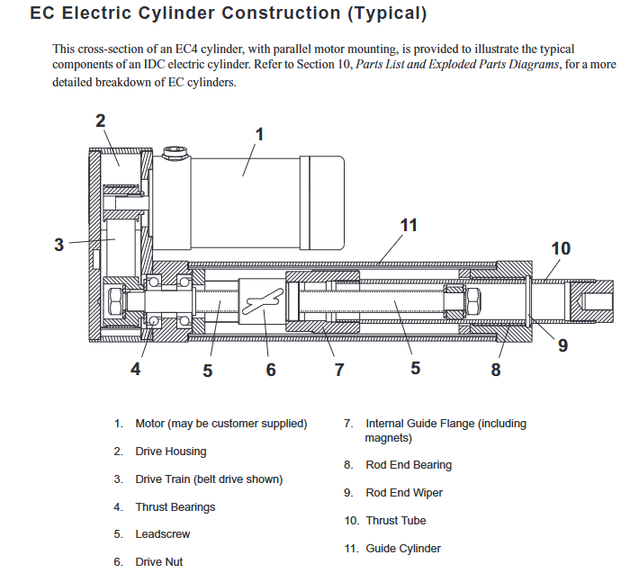
The IDC EC series electric cylinder includes four core models: EC2, EC3, EC4, and EC5, designed for precise control of linear thrust, speed, and position in the industrial, scientific, and commercial fields. It is an IDC high-performance electric cylinder product line, with the following core design highlights:
Structure: Adopting precision rolled ball screw (EC2/3 optional ACME screw), smooth transmission and precise positioning; Overall sealed design, standard IP54 protection, optional * * - PB protective boots achieve IP65 protection * *, preventing moisture and dry pollutants from entering;
Size: Complies with ISO6431 international standard, metric size, standard British/metric thread installation options;
Motor adaptation: Supports 24/160VDC brushed motors, 1.8 ° hybrid stepper motors, NEMA23/34/42 brushless servo motors, and can also be adapted to customer provided motors, with two installation methods: parallel/direct connection;
Core protection: All cylinder bodies come standard with ventilation pipe joints, and ventilation pipes need to be installed in specific scenarios to prevent internal pressure changes/pollutant intrusion.
Model Code and Configuration Rules
The EC series models are coded in combination, which can accurately identify all mechanical characteristics of the cylinder body through coding, and can also be customized according to coding requirements. The core coding dimensions and key configurations are shown in the table below:
table
Coding Dimension Core Options/Description Key Codes
Basic series four core models EC2/EC3/EC4/EC5
Motor type: DC brushed/stepper/brushless servo/customer provided D (24VDC)/H (160VDC)/P/S (stepper)/B (brushless)/X (self provided)
Transmission ratio belt/gear transmission, direct connection only 1:1 10 (1:1)/15 (1.5:1)/20 (2:1)/50 (5:1)/70 (7:1)/10L (direct connection)
Screw type ACME screw/ball screw, different lead 04A (4mm ACME)/05B (5mm ball)/10B/16A/25B/32B
The standard travel length is 50~1500mm, and it supports customized digital labeling in 1mm increments (unit: mm)
Installation methods: flange/fork/ear seat/ear shaft, etc. MF (flange)/MP (fork)/MS (ear seat)/MT (ear shaft)
Rod end type thread/fork/spherical joint FT (internal thread)/MT (external thread)/FC (fork)/FS (spherical)
Optional accessories include brake/encoder/potentiometer/protective boots, etc. - BS (screw brake)/- BM (motor brake)/- EMK (encoder)/- L (potentiometer)/- PB (protective boots)
Core Performance Parameters
The performance parameters of the four models differ significantly, with load capacity, no-load speed, and repeat positioning accuracy as the core distinguishing indicators. There are slight differences in performance when the same model is adapted to different motors. The core parameters are shown in the table below (with maximum values indicated):
table
Model Maximum Load Capacity Maximum Idle Speed Repetitive Positioning Accuracy Adaptation Screw Type Travel Range (mm)
EC2 3230N(740lbs) 840mm/s(33in/s) 0.13mm(0.005in) 04A/05B/16B 50~750, customizable
EC3 7200N(1620lbs) 930mm/s(36.5in/s) 0.025mm(0.001in) 04A/05B/10B/16B 50~1000, customizable
EC4 12000N(2700lbs) 1330mm/s(52.5in/s) 0.025mm(0.001in) 10B/25B 50~1500, customizable
EC5 25000N(5620lbs) 1330mm/s(52.5in/s) 0.013mm(0.0005in) 10B/32B 50~1500, customizable
Note: Customized travel for all models can be designed in increments of 1mm and adapted to different controllers (such as D2200/SmartStep/B8961).
Installation and commissioning specifications
Basic installation requirements
The installation structure should be able to bear three times the rated load of the cylinder body and have sufficient rigidity to prevent deformation of the cylinder body/support components;
The cylinder body must be parallel to the direction of load movement, and different installation methods correspond to different alignment accuracy requirements. When the deviation exceeds the limit, it will cause premature wear of internal components;
When using pivot installation (MP2/MP3/MT4)+pivot rod end (FS2/FC2), the cylinder body extension does not exceed 95% of the full stroke, improving system rigidity;
All installation surfaces must be flat and clean, and flat installation models (MF1/MF2/MF3/MS1/MS6) must be rigidly fixed.
Rod end installation and torque limitation
When installing the load, it is necessary to use the hexagonal plane of the thrust tube to prevent it from rotating, and it is strictly prohibited to exceed the maximum torque limit, otherwise it will damage the internal guide flange. The torque limits for each model are as follows:
table
Model: Clockwise maximum torque, counterclockwise maximum torque
EC2 68N-m(50ft-lbs) 27N-m(20ft-lbs)
EC3 88N-m(65ft-lbs) 41N-m(30ft-lbs)
EC4/5 163N-m(120ft-lbs) 68N-m(50ft-lbs)
Accuracy of cylinder body and load alignment
Different installation methods correspond to parallel/vertical alignment deviation limits. It is necessary to operate according to the specifications to allow the cylinder body to self align before tightening the screws. The core limits are as follows:
Flange/Fork/Ear Shaft Installation (MF/MP/MT): It is required that the installation surface has a vertical deviation of EC2 (0.03mm), EC3 (0.04mm), and EC4/5 (0.05mm) from the direction of load movement;
Ear seat/side hole installation (MS1/MS2/MS6): It is required that the deviation of the installation surface parallel to the direction of load movement increases with the increase of stroke, with a maximum deviation of 0.62mm for a stroke of 1500mm.
Installation of limit sensors
To prevent the cylinder block from hitting the hard limit, a position sensor (limit switch) must be installed, and the core requirements are:
Sensor types: PSR (mechanical spring), PSN/PSP (Hall effect), IP67 protection, PSR compatible with 8-120VAC/DC, PSN/PSP compatible with 5/12/24VDC;
Installation requirements: A deceleration distance should be reserved on the inner side of the hard limit, with a sensor spacing of ≥ 38.1mm (1.5 inches) and a tightening fixture screw torque of ≤ 7.0oz in;
Wiring specification: different sensors correspond to different wiring colors, shielded wires need to be reliably grounded, and PSP sensors are not compatible with IDC controllers.
Application Key Limitations
Column Load Limitation
When the screw is subjected to axial pressure, there is a critical load for instability. Exceeding this value will cause the screw to permanently bend. The maximum column load of different stroke/screw types varies significantly. The core rule is:
EC5 all specifications, 32B lead screw without column load limit;
As the stroke increases, the column load limit of other models significantly decreases, such as EC3 1000mm stroke 04A screw with a maximum column load of 4650N;
Customized trips can refer to the column load limit for the next shorter standard trip, or consult IDC engineers.
Critical speed limit
When the screw rotates, there is a resonance critical speed, and continuous overspeed can cause severe vibration and bending of the screw. The core requirements are:
The critical speed of different screw types/strokes varies, for example, the critical speed of EC5 32B screw 600mm stroke is 1333mm/s, and the critical speed of 1500mm stroke is reduced to 1120mm/s;
The IDC programmable controller can set the maximum speed parameter and force the speed to not exceed the critical value.
3.5.3 Duty cycle limitation
The duty cycle is the percentage of working time within a 10 minute cycle divided by the total cycle time, with a core limit of:
Ball screw cylinder body: 100% duty cycle rated;
ACME screw cylinder body: maximum 60% duty cycle;
The motor itself also has a duty cycle limit, which should be referred to in the motor manual. Exceeding the duty cycle can cause overheating and damage to the motor/internal components.
Environmental and Protection Requirements
Working temperature: -30 ℃~70 ℃ (-22 ℉~158 ℉), ventilation pipes must be installed when it is below 2 ℃ (35 ℉);
Pollution prevention: The standard version only protects against slight water mist. External protective covers are required for contact with corrosive/pressurized liquids, and * * - PB protective boots * * are required for contact with abrasive particles;
Ventilation pipe installation: - PB protective boots must be installed for work below 2 ℃ in dusty environments. EC2/3 uses 1/4 inch inner diameter pipes, EC4/5 uses 3/8 inches, and EC4/5 with - PB uses 3/4 inches.
Optional accessory specifications and installation
The EC series supports multiple customized accessories, all of which are factory pre installed/optional. The core accessory parameters are as follows:
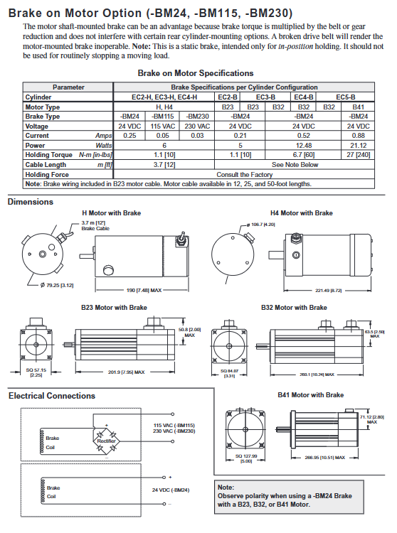
Brakes (- BS/- BM)
Only used for static positioning, not for braking motion loads, divided into screw end (- BS) and motor end (- BM), core parameters:
table
Type Voltage Options Core Performance Applicable Scenarios
-BS (screw end) 24VDC/115/230VAC EC2 maximum 3600N retention force, EC5 maximum 24800N requires high retention force, which does not affect the installation of the cylinder body at the rear end
-BM (motor end) 24VDC/115/230VAC brake torque is amplified by the transmission ratio. If the belt breaks, it will fail. There are installation restrictions at the rear end of the cylinder body, and there is no need for excessive positioning force
Encoder (- EM/- EMK)
Incremental rotary encoder for position feedback, core parameters:
-EM: 500 lines/rev, 2000 pulses/rev after orthogonal output;
-EMK: 1000 lines/rev, 4000 pulses/rev after orthogonal output;
The brushless servo motor (B23/B32/B41) comes standard with a 2000 line/rotary encoder and outputs 8000 pulses/revolution;
Power supply: 5VDC ± 5%, maximum speed 6000~12000rpm, cable length 3.7m (12ft).
Linear Potentiometer (- L)
Built in cylinder body, linear displacement through simulated voltage feedback, 0% stroke corresponds to 0VDC, 100% stroke corresponds to supply voltage, core parameters:
Resistance value: 50mm stroke 3000 Ω, 600mm stroke 7000 Ω, tolerance ± 20%~30%;
Non linearity: maximum ± 1%, not recommended for use in high vibration environments;
Power supply: External DC power supply, with brown (+VDC), black (feedback), and blue (GND) wiring.
Protective Boots (- PB)
Realize IP65 protection level, wrap the thrust tube/oil scraping sealing surface to prevent moisture and dry particles from entering. All models are optional and need to be used in conjunction with the vent pipe after installation.
Daily Maintenance and Factory Services
Maintenance Classification and Operating Scope
On site routine maintenance: only belt tensioning, screw/gear lubrication, motor small gear alignment, and replacement of vulnerable parts (belt/rod end) are allowed;
Factory services: complex operations such as screw modification, transmission ratio replacement, accessory installation (- BS/- L), internal component maintenance, etc. must be returned to the factory.
Core maintenance cycle and specifications
Lubrication cycle:
ACME lead screw (EC2/3): 200000 inch stroke re lubricated;
Ball screws (all models): Re lubricate with a stroke of 1000000 inches;
Lubricants: NLGI grade 2 synthetic lithium grease is used for ball screws, NLGI grade 2 synthetic grease containing PTFE is used for ACME screws, and NLGI grade 2 synthetic lithium based composite extreme pressure grease is used for gears.
Belt tension inspection: The maximum deflection of the transmission belt is ≤ 3.17mm (0.125 inches), and if it exceeds the tolerance, the motor position needs to be adjusted for tension.
Gear mesh clearance: After the motor small gear meshes with the intermediate gear, it needs to be retracted by 0.076~0.203mm (0.003~0.008 inches) to ensure the mesh clearance.
Hardware torque: All maintenance operations require tightening screws according to standard torque, such as M10X1.5 screws with a maximum torque of 41N-m (362.86in-lbs).
Customer provided motor installation
Support the adaptation of customer provided motors, core steps:
Install the pulley/pinion/coupling, apply Loctite 680 (green), and tighten the screws with Loctite 262 (red);
Adjust the spacing between pulleys/small gears according to specifications (such as EC2 pulley spacing of 11.63mm);
Belt transmission requires tensioning the belt, gear transmission requires centering the mesh clearance, and direct transmission requires alignment with the coupling;
Tighten the motor mounting screws to ensure that the motor flange is in contact with the mounting plate.
Troubleshooting
The manual provides clear fault symptoms, causes, and solutions for the four major types of faults in electric cylinder machinery, motion, positioning, and accessories. The core faults and troubleshooting ideas are as follows:
Abnormal noise/jamming/shaking: mostly caused by poor alignment between the cylinder body and load, excessive side load, insufficient lubrication, foreign object intrusion. If the side load exceeds the limit, the load needs to be reduced, and foreign object intrusion/internal component damage needs to be returned to the factory for inspection;
Motor not turning/abnormal speed: The motor is not connected/damaged, the load exceeds the limit, the belt slips/breaks, the gear mesh is poor, the belt slips and needs to be re tensioned, and the gear is damaged and needs to be returned to the factory;
Inaccurate positioning/backdrive: large load changes, controller parameter errors (screw lead/transmission ratio), improper sensor position, insufficient brake retention force, need to correct controller parameters and adjust sensor position;
Accessory failure: Sensor/encoder wiring error/damage, brake overload/wiring error, wiring needs to be checked, damaged accessories need to be replaced, brake overload needs to be reduced.
Components
Parts List: Provides a complete list of 63 components and exploded diagrams for the EC series, divided into four types: EC2/3, EC4/5, and parallel/direct motor installation. Accessories can be ordered through IDC authorized dealers;
Warranty policy: 1-year original factory warranty. From the date of shipment, free repair/replacement is provided for faults caused by material/process defects. Faults caused by human misuse, improper installation, or improper maintenance are not covered by warranty.
- YOKOGAWA
- Reliance
- ADVANCED
- SEW
- ProSoft
- WATLOW
- Kongsberg
- FANUC
- VSD
- DCS
- PLC
- man-machine
- Covid-19
- Energy and Gender
- Energy Access
- Renewable Integration
- Energy Subsidies
- Energy and Water
- Net zero emission
- Energy Security
- Critical Minerals
- A-B
- petroleum
- Mine scale
- Sewage treatment
- cement
- architecture
- Industrial information
- New energy
- Automobile market
- electricity
- Construction site
- HIMA
- ABB
- Rockwell
- Schneider Modicon
- Siemens
- xYCOM
- Yaskawa
- Woodward
- BOSCH Rexroth
- MOOG
- General Electric
- American NI
- Rolls-Royce
- CTI
- Honeywell
- EMERSON
- MAN
- GE
- TRICONEX
- Control Wave
- ALSTOM
- AMAT
- STUDER
- KONGSBERG
- MOTOROLA
- DANAHER MOTION
- Bentley
- Galil
- EATON
- MOLEX
- Triconex
- DEIF
- B&W
- ZYGO
- Aerotech
- DANFOSS
- KOLLMORGEN
- Beijer
- Endress+Hauser
- schneider
- Foxboro
- KB
- REXROTH
- YAMAHA
- Johnson
- Westinghouse
- WAGO
- TOSHIBA
- TEKTRONIX
- BENDER
- BMCM
- SMC
- HITACHI
- HIRSCHMANN
- XP POWER
- Baldor
- Meggitt
- SHINKAWA
- Other Brands
- UniOP
- KUKA
- IBA
-
LTI Drives CDF30.002.C0.7 Compact Servo Controller 08685963 DC 24V Industrial Module
-
LUST LTI Drives CDB32.008.W2.4.BR.PC1 Servo Drive Industrial Motion System
-
LUST LTI Drives CDB34.003.C2.4.PC1.H15 Servo Motor Driver Industrial Control Unit
-
LUST LTI Drives CDA32.004.C1.4.H08.B0 Servo Drive Mat. 3084456 Industrial Control
-
LUST LTI Drives CDE34.005.W2.2 Industrial Servo Drive Motion Control Unit
-
LUST LTI Drives CDA34.006.W3.0 Servo Drive Software V3.70-04 Industrial Controller
-
LTI Drives CDB32.004.C2.4.SH Servo Drive Compact Motion Controller
-
Woodward 9905-373 - Digital Synchronizer And Load Controller
-
WOODWARD MAGNETIC PICKUPS - Sensor
-
WOODWARD GCP-30 - Steuertafel for Industrial Regulator Genset Control Package
-
WOODWARD GOVERNOR 9907-1183 REV A - 505 ENHANCED TURBINE CONTROL
-
WOODWARD 9907-173 REV B - Module Load Sharing 120 Volt
-
WOODWARD 9907-014 - 2301A controller
-
Woodward 9905-029 - SPM-A Synchronizer Module Rev C
-
WOODWARD 8440-1799 EASYGEN-350 REV B - Genset Controller
-
WOODWARD 5466-258 REV M - SIMPLEX DISCRETE I/O MODULE
-
Woodward 8440-1884 C - Controller Easygen 2500-5
-
Woodward 8441-1153 - Monitoring Unit 250VAC
-
WOODWARD 8406-120 REV G - EGCP-2 DIGITAL CONTROL
-
Woodward 8273-584 - Atlas-ii Digital Control
-
Woodward 8272-582 - APM Motor Control 8272582
-
Woodward 9905-377 Rev. A - 2301A Load Sharing and Speed Control
-
WOODWARD 8272-517 - Pm Motor Control
-
WOODWARD 9905-797 REV.B - DIGITAL SYNCHRONIZER AND LOAD CONTROL DSLC-D
-
WOODWARD 8272-582 - APM MOTOR CONTROL
-
Woodward Seg FP2-8-24 - Emergency Power Telecommunications Module NP2
-
WOODWARD 2001-12E2U1B1S1A - Fuel Shut Off Valve Stop Solenoid Valve 2000-4505
-
Woodward 8440-1884 K - Genset Controller Easygen-2500-5
-
Woodward 9905-760 - Linknet Termination Module
-
Woodward 8404-009 - Proact Digital Plus Front Panel Rev. H
-
Woodward 8271-651 - Digital Speed Reference
-
Woodward 3077-474C - 8605895 5501-031 D Circuit Module
-
WOODWARD 5466-257 REV.-C - NETCON 5000 MODEL REMOTE TRANSCEIVER I/O MODULE
-
Woodward 8273-101 Rev: A - 2301D Digital Load Sharing and Speed Control
-
WOODWARD 8272-799 - 2301A SPEED CONTROL WITH REMOTE REFERENCE REV:C
-
Woodward 8272-517 - PM Motor Control
-
Woodward 8290-048 8290048 Rev. F - Generator Load Sensor
-
woodward 8273-1012 rev c - 2301e Load Sharing and Speed Control
-
WOODWARD 9905-797 - DIGITAL SYNCHRONIZER AND LOAD CONTROL FOR 3 PHASE GENERATORS
-
WOODWARD 8280-3014 - 723 PLUS DIGITAL CONTROL REV NEW
-
WOODWARD 8440-1884 REV G - GENSET CONTROLLER EASYGEN-2500-5/P1
-
Woodward 8272-683 K - Digital Reference
-
WOODWARD 9907-014 - SPEED CONTROL 2301A REV H
-
Woodward Type UG-8 P/N 037260 - Governor R.P.M 1075-1650 Motor KM58-20
-
WOODWARD 9905-970 - LINKNET 6 CHANNEL 100 OHM RTD Rev:J
-
Woodward 9907-1183 Rev C - Steam Turbine Digital SCREEN 505E Turbine Control
-
Woodward 8440-1614 - GCP-30 Genset Control Package, Rev: F, Type 1, E231544
-
Woodward DC11006-304-024 - ACTUOTOR DYNA ACTUATOR - BARBER-COLMAN
-
Woodward 9905-971 - LINKNET 6 CHANNEL 100 OHM RTD Rev:K
-
Woodward DYNK-10249 - Actuator Controller Kit - DYNA 2000
-
Woodward LR21035 - MFR1 MULTI FUNCTION RELAY REV F
-
Woodward 8440-1831 - EASYGEN 3200-5 P/N: REV. G Gererator Controller
-
Woodward 8272-516 - PM MOTOR CONTROL REV J
-
Woodward 8440-2080 - EASYGEN 2000 genset controller EASYGEN-2300-5/P1
-
Woodward 505DE - Digital Control System
-
Woodward 701 - Digital Speed Control 18-40 VDC 4-20 MA
-
Woodward 8440-1799 - EASYGEN-350 REV B
-
Woodward 8272-582 - Apm Motor Control 100-220v AC/DC
-
Woodward 5501-031 D - 3077-474C 8605895 Circuit Module
-
Woodward XD1-T - XD1T55SAT TRANSFORMER DIFFERENTIAL PROTECTION RELAY
-
Woodward 8272-517 - PM Motor Control 220vac
-
Woodward 8934-658 - Repair Kit UG8D Governor
-
Woodward 5437 18 - module netcon derivative analog rev.A
-
Woodward 8272-171 A - Pm Motor Control
-
Woodward MRN3-1/2 - SEG mains uncoupling relay MRN314D mains decoupling relay
-
Woodward 9905-373 - Digital Synchronizer and Load Control 18-40 VDC Rev P
-
Woodward 5431-640 C - Dual Dynamics 1000 Series Speed Control Module
-
Woodward 5501-031 D - 3077-474C 8605895 Circuit Module
-
Woodward 9907-247 - 828 DIGITAL CONTROL
-
Woodward 8440-1855-G - EASYGEN-2200-5 /P1 12/24VDC GENSET CONTROLLER
-
Woodward NC3-2-8 (NO) - GENERATOR CONTROLLER
-
Woodward 8271-467 K - 2301 LOAD SHARING AND SPEED CONTROL PART NO:
-
Woodward 8440-2177 A - SPM-D2-10 Digital Synchronising Controller
-
Woodward LXMG1614E-14-11 - CCFL and UV Lamps Inverter Module
-
Woodward 8270-990 - signal converter
-
Woodward 9905-068 - LOW VOLTAGE 2301A LOAD SHARING & SPEED CONTOL P/N:
-
Woodward 8901-051 - BOOSTER SERVOMOTOR, SINGLE CYLINDER, 2:1
-
Woodward 8444-1024 D - MWS4-55M CONTROL MODULE UNIT
-
Woodward 5448-914 - GCP-20 Genset Control GCP-20 REV D P/n:
-
Danfoss BHA-1 018-1942 - Hydraulic Actuator
-
Woodward 9905-001 L - SPM-A SYNCHRONIZER
-
Woodward 5464-850 - Module
-
Woodward 5501-371 - Micronet Simplex Mpu Aio Rev C
-
Woodward 8272-132 B - POWER SENSOR
-
Woodward 9907-028 - SPM-A Synchronizer
-
Woodward SA-3678-AM-2 - Overspeed Electric Governor, Model ESSE2-AM
-
Woodward E8250-502 - GOVERNOR ACTUATOR
-
Woodward 8440-1884 J - Controller EASYGEN-2500-5
-
Woodward 5441-693 - DIGITAL I/O MODULE -MISSING PART
-
Woodward SA-4450 - Speed Controller APECS 3100 For Magnetic Pickup
-
Woodward 9903-466 - 701 DIGITAL SPEED CONTROL REV G
-
Woodward 1765-843 - Governor Speed Adjusting Motor P/N Type: SMM40 220V AC 50/60Hz
-
Woodward 9905-760 - Linknet Termination Module
-
Woodward 9907-247 - 828 DIGITAL CONTROL UNIT REV K
-
Woodward 5484-721 - motor
-
Woodward 8440-1734 - MFR-2 Rev.A Multi Function Relay MFR-2
-
Woodward CSC3SUWA - Controller
-
Woodward 8440-1667 - REV B SPM-D1010B/XN
-
Woodward 8406-120 - egcp-2 digital control
-
Woodward DPG-2201-002 - DIGITAL CONTROLLER REV D
-
Woodward 8272-516 - Pm Engine Control Rev J
-
Woodward 8440-1831 - EASYGEN 3200-5 P/N: REV. K - WITHOUT ACCESSORIES
-
Woodward 8273-101 - LOAD SHARING & SPEED CONTROL
-
Woodward 8440-1855-G - EASYGEN-2200-5 /P1 12/24VDC GENSET CONTROLLER
-
Woodward 9907-247 - 828 DIGITAL CONTROL UNIT REV K
-
Woodward LR21035 - MFR1 MULTI FUNCTION RELAY REV J
-
Woodward 8404-009 - PROACT DIGITAL PLUS FRONT PANEL REV J
-
Woodward 9905-204 - Rev N SPM-A synchronizer
-
Woodward 8521-367 - UG-8 P/N r R.P.M 750-1280 Governor / UG8
-
Woodward 9907-175 - Load Sharing Module Rev. B
-
Woodward 5464-645 - DRIVER MODULE REV A 2C ACT DRIVE
-
Woodward 8404-009 - PROACT DIGITAL PLUS FRONT PANEL REV J
-
Woodward 9907-175 - Load Sharing Module Rev. B
-
Woodward 8406-102 - Rev A EGCP-2 Digital Control Engine Generator 8406102
-
Woodward EASYGEN-2500-5 - Controller Genset
-
Woodward 8440-2082 - Controller
-
Woodward 8272-516 - PM MOTOR CONTROL REV J
-
Woodward 9905-373 - Digital Synchronizer and Load Control 18-40 VDC Rev P
-
Woodward 5501-429 - Actuator Controller 25mA 2 Channel , (UPP)
-
Woodward 8440-1869 - SPM-D10 Synchronizing System Control-SPM-D10B/PSY4-F-D
-
Woodward 9907-175 - Load Sharing Module Rev. A
-
Woodward 8200-224 - Servo Position Controller
-
Woodward 9906-619 - 723 PLUS DIGITAL CONTROL ( 8280-604 )
-
Woodward 8440-1519 - EASYGEN PART NO: REV: 4
-
Woodward 5501-371 - REV C MODULE- MICRONET SIMPLEX MPU & AIO FTM
-
Woodward EASYGEN-3200-5/P1 - Generator Controller Module Rev F
-
Woodward 8440-1884K - GENERATOR CONTROLLER EASYGEN-2500-5 REV,K
-
Woodward 5466-353 - REV C NETCON MAIN CHASSIS TRANSCEIVER

K-JIANG

Add: Jimei North Road, Jimei District, Xiamen, Fujian, China
Tell:+86-15305925923