
K-WANG


Danfoss VACON NXI Inverter FI9-FI14 Operation Guide
Danfoss VACON NXI series FI9-FI14 frequency converter comprehensive technical operation and maintenance guide
Introduction: The core driving force of industrial drive
In the field of modern industrial automation, high-performance AC frequency converters are the core equipment for driving motors to operate efficiently. Vacon launched by Danfoss ® The NXI series inverters, as an upgrade and expansion of the ∑ - II series, are known for their modular design and powerful performance. Especially the high-power models with frame sizes ranging from FI9 to FI14 are widely used in harsh industrial environments. This article is based on the official operating manual (document number: DPD00909E), which provides a detailed overview of the core technical parameters, safety installation specifications, electrical wiring details, and debugging and maintenance processes of VACON NXI inverters. The aim is to provide electrical engineers with a comprehensive and professional technical reference material.
Safety regulations: the cornerstone of operation
Understanding and complying with safety regulations before coming into contact with any high-voltage equipment is the first line of defense against personal injury and equipment damage. The NXI series frequency converters involve high-voltage direct current (DC) power supply, and their potential hazards are much higher than conventional AC frequency converters.
1.1 Definition of hazard level
The manual clearly divides four safety warning levels:
DANGER: Involves a risk of death or serious injury. For example, when an inverter is connected to a DC power source, its power unit components, motor terminals (U, V, W), and DC terminals (B+, B -) all carry dangerous voltages, even if the motor stops running.
Warning: May result in death or serious injury. For example, if the leakage current exceeds 3.5 mA, reliable grounding must be ensured; The control terminal may still carry dangerous voltage after the external power supply is disconnected.
CAUTION: May cause minor injury or equipment damage. Connecting a three-phase power supply to the output terminal may cause damage to the equipment.
NOTICE: A warning for equipment damage, such as electrostatic discharge (ESD), which may damage the circuit board.
1.2 Key Safety Operating Procedures
Power off waiting: After disconnecting the DC power supply, it is necessary to wait for at least 5 minutes for the DC link capacitor to discharge before opening the cabinet door or conducting maintenance.
Prevent accidental startup: After parameter changes or reset faults, if the startup signal is in an active state, the motor may start immediately. Be sure to disconnect the motor connection or ensure that the emergency stop program is ready before operation.
Grounding requirements: Due to excessive leakage current, the equipment must be reliably grounded by a qualified electrician. In addition, the frequency converter may cause direct current to be generated in the PE conductor, and a B-type residual current operated protective device (RCD) needs to be used on the power supply side.
Product Overview and Model Definition
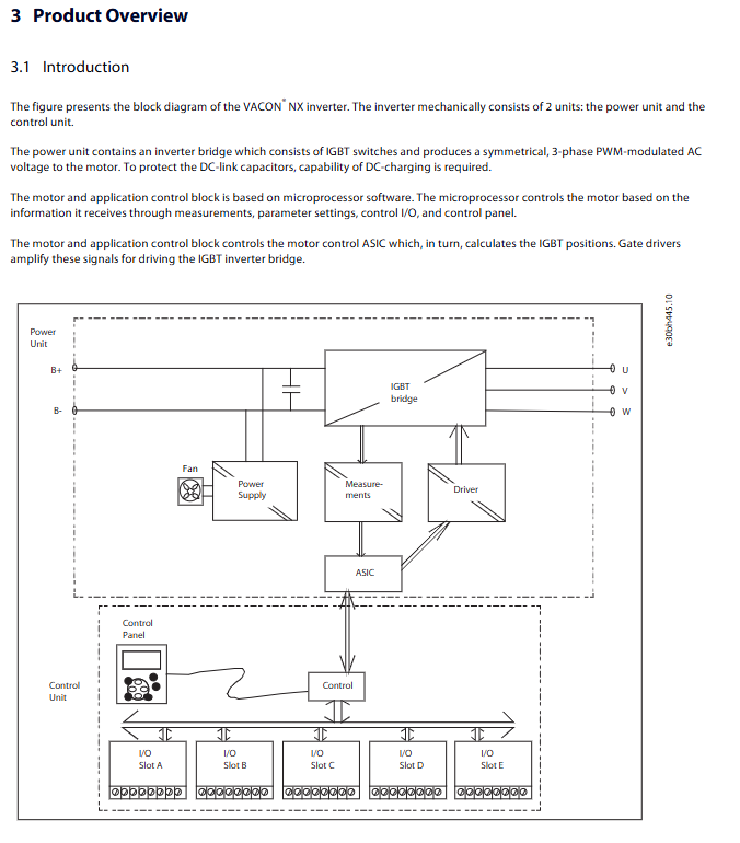
The VACON NXI inverter consists of a power unit and a control unit. The power unit includes an IGBT inverter bridge that generates three-phase PWM modulated AC voltage; The control unit is based on microprocessor software and processes parameters, I/O signals, and control panel instructions.
2.1 Model Code Analysis
Correctly interpreting the model code is the foundation of selection and maintenance. The code format is: NXI00035-A2T0ISF-A1A2C30000+DNOT.
NXI: Product series.
00035: Rated current (ampere).
5/6: Power supply voltage code. 5 represents 380-500 V AC (corresponding to DC 465-800 V), and 6 represents 525-690 V AC (corresponding to DC 640-1100 V).
A/B/F/G: Control panel type (A is standard text display).
ISF: Hardware change code (I=INO without charging circuit, S=standard air cooling, F=fiber optic connection).
Option board code: A=Basic I/O board, C=Fieldbus board.
2.2 Framework size and protection level
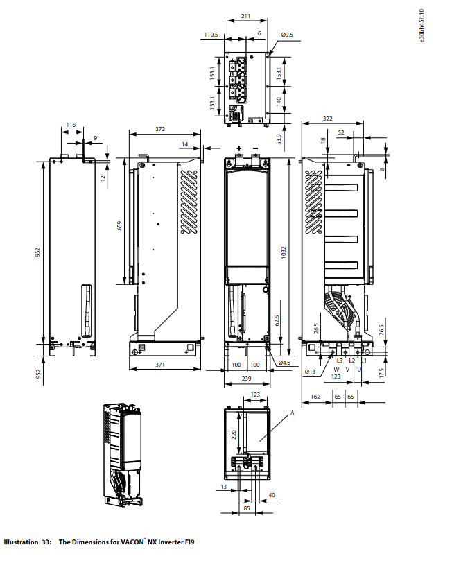
The NXI series covers frame sizes from FI9 to FI14, with weight increasing from 65kg for FI9 to 604kg for FI14. In terms of protection level, the standard configuration for FI9-FI14 is IP00 (open), with optional IP21/UL Type 1. The default EMC rating at the factory is Class T (Category C4), which meets the anti-interference requirements of industrial environments.
Mechanical installation and environmental control
Proper mechanical installation is the foundation for ensuring the long-term stable operation of frequency converters, especially for high-power equipment where heat dissipation and spatial layout are crucial.
3.1 Environmental Requirements
Temperature: The ambient temperature should be controlled between 0 ° C and 55 ° C. If the temperature exceeds 40 ° C, it needs to be downgraded according to the formula: Pde=Pn * (100% - (t-40) * x/100).
Altitude: When the altitude exceeds 1000 meters, the decrease in air density leads to a decrease in cooling capacity, and the current needs to be reduced by 1%/100m. Altitude also affects insulation strength and the cooling of fuses.
Cleanliness: The installation environment should be free of corrosive gases and conductive dust, with humidity maintained below 90% RH and no condensation.
3.2 Installation spacing and cooling
FI9 to FI14 inverters are forcibly cooled by fans. Sufficient heat dissipation space must be reserved during installation:
A space of at least 200mm should be left above the equipment.
A space of at least 300mm should be left below the equipment.
If multiple inverters are installed side by side, the equipment spacing should be at least 10mm.
If installed inside the control cabinet, the required cooling air volume must be calculated (such as 750 m ³/h for FI9), and appropriate inlet and outlet ports must be designed on the cabinet door to ensure effective discharge of hot air outside the cabinet.
Electrical installation and wiring specifications
The quality of electrical installation is directly related to the electromagnetic compatibility (EMC) and operational safety of the system.
4.1 Power and motor wiring
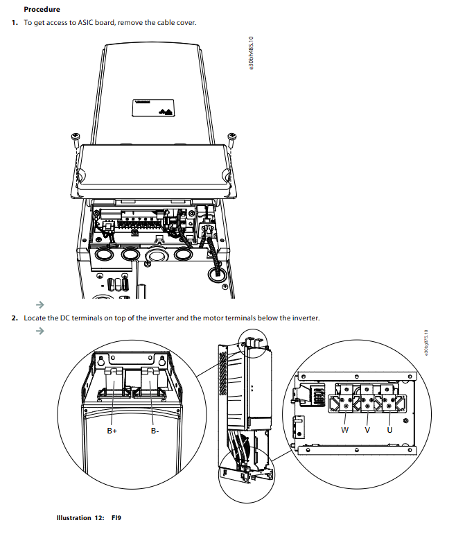
The NXI series inverters use DC power supply, with power cables connected to B+and B - terminals, and motor cables connected to U, V, and W terminals.
Fuse selection: High performance fuses that comply with IEC standards (such as Bussman aR or gR type) must be used to provide short-circuit protection. The manual provides a detailed list of recommended fuse models and sizes for different power levels.
Cable specifications: It is recommended to use PVC insulated cables with concentric copper shielding layers, with a temperature resistance of at least 70 ° C. The cable cross-sectional area should comply with EN 60204-1 standard.
Grounding: The shielding layer needs to be connected to a 360 ° ground through conductive metal fixtures to meet EMC requirements. The cross-sectional area of the grounding conductor must meet the minimum requirement of 10mm ² copper wire or 16mm ² aluminum wire.
4.2 EMC compliant installation
In order to comply with the EMC directive, attention should be paid to the following during installation:
The shielding layer at both ends of the motor cable must be grounded 360 ° through a Grommet.
Control cables should be kept away from power cables, and if they must be crossed, they should be crossed at a 90 ° right angle.
The installation of input reactors or filters helps to reduce harmonic interference.
Control unit and terminal configuration
The control unit is the "brain" of the inverter, connecting the base board and option board through slots (A-E).
5.1 Control voltage
The control unit supports external+24 V DC power supply (± 10%, minimum 1000 mA). This allows parameter settings and communication to still be carried out even when the main power supply is disconnected. Attention should be paid to connecting diodes in series in the external power supply circuit to prevent current backflow, and installing a 1A fuse.
5.2 OPTA1 Basic Board Terminal
OPTA1 board provides 20 control terminals with rich functions:
Analog input: AI1/AI2 can select voltage (0-10V) or current (0/4-20mA) signals through jumper X1, and even support joystick control from -10V to+10V.
Digital input: 6-way digital input (DIN1-6), supporting source or drain connections.
Output: Includes relay output and analog output.
Jumper settings: X1/X2 set analog mode, X3 set common terminal (CMA/CMB) isolation, X6 set analog output mode.
5.3 Fiber optic communication
For large-sized models such as FI12 and FI14, the control unit and power unit are connected through fiber optic cables to effectively isolate strong electrical interference. When connecting, pay attention to the minimum bending radius (50mm) and check the number (1-8) to prevent damage to the power device caused by connection errors.
Control panel operation and parameter settings
VACON NXI is equipped with a powerful control panel that includes 9 buttons and an LCD display screen.
6.1 Menu Structure
M1 monitoring menu: Real time viewing of operating data such as output frequency, current, torque, DC link voltage, etc.
M2 parameter menu: divided into parameter groups (G1-G8), including motor nameplate parameters, control logic, protection settings, etc.
M3 keyboard control menu: used to switch control locations (I/O terminals, keyboard, fieldbus), set frequency reference values and motor rotation directions.
M6 system menu:
Language selection and application selection.
Parameter copying (upload/download).
Security settings (password lock, parameter lock).
Hardware settings (fan control, brake resistor connection status).
System information (counter, software version).
6.2 Startup Wizard
When powered on for the first time, the activated startup wizard will guide the user to set the language, application type, and motor nameplate parameters (rated voltage, frequency, speed, current). After completing these settings, the frequency converter can be put into basic operation.
Debugging and trial operation
The debugging process must follow strict steps to ensure the safety of personnel and equipment.
7.1 Insulation inspection
Before powering on, it is necessary to measure the insulation resistance of the motor cable and motor. Disconnect the cable from the frequency converter and use a 500V DC megohmmeter to measure the insulation resistance. The insulation resistance should be greater than 1 M Ω. Do not perform a voltage withstand test on the main circuit of the frequency converter to avoid damaging the internal electronic components.
7.2 Trial operation steps
No load test: Disconnect the motor from the load and set the load inertia parameter to 0. Perform jog or short-term operation to check the motor direction and frequency converter response.
Load test: Before connecting the load, confirm that the mechanical part is allowed to start. Set the maximum frequency reference for startup testing.
Parameter optimization: Adjust acceleration/deceleration time, PID parameters, etc. based on actual load characteristics.
Maintenance and troubleshooting
8.1 Maintenance cycle
Although the frequency converter is designed to be maintenance free, regular inspections are essential
Every 6-24 months: Check the terminal tightening torque, clean the radiator dust, and check the operation of the cooling fan.
Every 5-7 years: Replace the cooling fan. The lifespan of a fan is greatly affected by environmental temperature.
Every 8-15 years: Replace the DC link capacitor. The lifespan of a capacitor depends on the ambient temperature and average load.
8.2 Capacitor Empowerment (Reforming)
If the frequency converter is stored for more than 2 years without use, the oxide layer of the internal electrolytic capacitor may degrade, and direct electrification may cause damage to the capacitor. Empowerment processing must be carried out:
Connect the adjustable DC power supply to the B+/B - terminals.
Limit the current to below 800 mA.
Slowly increase the voltage to the rated value and maintain it for a period of time (the specific time depends on the storage duration).
8.3 Fault diagnosis
There are four types of faults:
A (Alarm): Alarm, do not stop.
F (Fault): Fault, stop running.
AR (Autoreset): Automatic reset fault, try restarting.
FT (Fault Trip): Trip after reboot failure.
Common fault codes and countermeasures:
F1 overcurrent: Check for motor short circuit, overload, or incorrect parameter settings.
F2 overvoltage: Check if the deceleration time is too short, if the load is generating electricity, and install a braking resistor if necessary.
F3 grounding fault: Check the insulation of the motor cable or winding.
F8 system malfunction: usually involves hardware communication or internal component damage, and the manufacturer needs to be contacted.
F30 STO fault: The safety torque shutdown function is activated, and the safety circuit wiring needs to be checked.
Summary of Technical Specifications
Rated voltage: AC 380-500V/525-690V.
Output frequency: 0-320 Hz.
Overload capacity:
Low load mode: 110% overload for 1 minute/10 minutes.
High load mode: 150% overload for 1 minute/10 minutes.
Protection level: IP00/IP21 (UL Type 1).
Cooling method: forced air cooling.
- YOKOGAWA
- Reliance
- ADVANCED
- SEW
- ProSoft
- WATLOW
- Kongsberg
- FANUC
- VSD
- DCS
- PLC
- man-machine
- Covid-19
- Energy and Gender
- Energy Access
- Renewable Integration
- Energy Subsidies
- Energy and Water
- Net zero emission
- Energy Security
- Critical Minerals
- A-B
- petroleum
- Mine scale
- Sewage treatment
- cement
- architecture
- Industrial information
- New energy
- Automobile market
- electricity
- Construction site
- HIMA
- ABB
- Rockwell
- Schneider Modicon
- Siemens
- xYCOM
- Yaskawa
- Woodward
- BOSCH Rexroth
- MOOG
- General Electric
- American NI
- Rolls-Royce
- CTI
- Honeywell
- EMERSON
- MAN
- GE
- TRICONEX
- Control Wave
- ALSTOM
- AMAT
- STUDER
- KONGSBERG
- MOTOROLA
- DANAHER MOTION
- Bentley
- Galil
- EATON
- MOLEX
- Triconex
- DEIF
- B&W
- ZYGO
- Aerotech
- DANFOSS
- KOLLMORGEN
- Beijer
- Endress+Hauser
- schneider
- Foxboro
- KB
- REXROTH
- YAMAHA
- Johnson
- Westinghouse
- WAGO
- TOSHIBA
- TEKTRONIX
- BENDER
- BMCM
- SMC
- HITACHI
- HIRSCHMANN
- XP POWER
- Baldor
- Meggitt
- SHINKAWA
- Other Brands
- UniOP
- KUKA
- IBA
- Beckhoff
-
Basler Electric DECS-250-CN1SN1N Automatic Voltage Regulator for Generator Excitation Control
-
ADLINK CPCI-6860A - 51-31310-OB10 industrial motherboard CompactPCI SBC
-
ADLINK AmITX-SL-G-H110 - 51-7A104-0A30 Mini-ITX Industrial Motherboard
-
ADLINK PXI-2005-003 - CPCI Industrial PC Data Acquisition Card Multi-Function DAQ
-
ADLINK DININ-814M - 51-14032-0A3D SCSI-100P cable connection Interface Terminal Board
-
ADLINK CPCI-3920NA/C2D15/M1G - 3U CompactPCI Intel Core 2 Duo Single Board Computer
-
ADLINK PCIE-8560 - 51-18014-0A20 Communication Card High Speed DAQ
-
ADLINK PCI-C154+ - Motion Control Card 4-axis Motion Controller Board
-
ADLINK PCI-RTV24 - image capture card Analog Video Frame Grabber
-
ADLINK NuPRO-842LV/P - 51-41360-0B30 Industrial Motherboard CPU Board
-
ADLINK cBP-3208/3208R - CPCI Board 3U 8-Slot CompactPCI Backplane
-
ADLINK PCI-8164 - 4-Axis Motion Controller PCI Card 51-12406-0A40
-
ADLINK PCIe-GIE64+ - 4-CH GigE Vision PoE+ Frame Grabber Video Capture Card
-
ADLINK CPCI-6860 / 6860A - CompactPCI Dual Xeon Single Board Computer
-
ADLINK IEC-915GV - REV 1.1 Industrial motherboard CPU Board
-
ADLINK ND-6520 - Technology RS-232 to RS-422RS-485 Converter NuDAM Module
-
ADLINK RTV-24 / PCI-MP4S - 51-12519-1C30 4-Channel Real Time Video Capture Board
-
ADLINK cPCI-6910 / cPCI-6910AM/M1G - cPCI-6910AM/DXL16/M1G/S80G(G)-3120 BOARD CompactPCI SBC
-
ADLINK NUPRO-A40H - Linghua 51-41807-1A30 Industrial Control Computer Motherboard
-
ADLINK USB-3488A - USB to GPIB INTERFACE USB-3488A(G) Controller Module
-
ADLINK PCI-8134A - motion control card 4-Axis Controller Card
-
ADLINK PCI-7432 - Board 32-Channel input / 32-output Isolated Digital I/O PCI Card
-
ADLINK PCI-8134A - 51-12421-0A10 motion controller card tested
-
ADLINK LPCIe-7230 - 32 CH Isolated Input/output Card 2 Interrupts Low Profile PCIe
-
ADLINK NuPRO-E340 - industrial computer motherboard 51-47807-0A30 PICMG 1.3 SHB
-
ADLINK PCI-7434 - High-speed Digital Acquisition Card 64-CH Isolated DO Card
-
ADLINK NuPRO-E330 - 51-41805-0A20 Indsutrial Board SHB Single Board Computer
-
ADLINK PCI-7248 - OPTO-22 48 CHANNEL DIO DIGITAL TTL/DTL I/O 51-12006-0A40 GP
-
ADLINK PCI-8134 - Motion control card 4-Axis Controller Card
-
ADLINK AMP-208C - Movimiento Control Tarjeta 51-12420-1A20 W/Expansión & Breakout
-
ADLINK PCI-8164 - 51-12406-0A40 PCB Board 4-Axis Motion Controller Card
-
ADLINK DIN-68Y-SGII / DIN-68M-J3A - Terminal Board Connector Interface Block
-
ADLINK PCIe-7432 - Technology 51-18402-0A10 PCIe Card With High Input Range
-
ADLINK PCI-8144 / PCI-8144N - Motion control card 4-Axis Stepper Controller Card
-
ADLINK HSL-HUB3/REPEATER - HIGH SPEED LINK EXTENSION MODULES Distributed Hub Module
-
ADLINK ND-6017 - Data Logging + Acquisition 8CH A/D input Mod NuDAM Module
-
ADLINK LPCIe-7250 - data acquisition card Low Profile 8-CH Relay Output Card
-
ADLINK PCI-7432 - I/O card 64-CH Isolated Digital Input Output PCI Card
-
ADLINK IMB-M43H - industrial control computer motherboard Q87 Chip Micro-ATX
-
ADLINK MP-C154 - Motion control Card 4-Axis Motion Controller Board
-
ADLINK PCI-RTV24 - image capture card Video Frame Grabber Card
-
ADLINK PCI-7250 - 8-CH Relay Output & 8-CH Isolated DI Card
-
ADLINK PCI-6308V - 8-CH 12-Bit Isolated Analog Output PCI Card PCB-I-E-1148=6EX2
-
ADLINK PCI-7248 - capture card 48-CH Opto-22 Compatible DIO Card
-
ADLINK HSL-AI16A02-M-VV - Analog Input Output Distributed Module
-
ADLINK NuPRO-A301 - Rev:1.4 NUPRO-A301 PICMG Full-Size Single Board Computer
-
ADLINK PCI-6208V-GL - 8-CH Voltage Analog Output PCI Card
-
ADLINK PCI-8134A - 51-12421-0A10 4-Axis Motion Controller Card
-
ADLINK MNET-S23 - TECHNOLOGY MNET S23 - SERVO DRIVER CONTROL MODULE
-
ADLINK M-342 - ATX I3 I5 I7 Q67 Industrial Motherboard
-
ADLINK NUPRO-780 - Industrial Motherboard CPU Board PICMG SBC
-
ADLINK MP-C154 / MP-C152 - 4-Axis Motion Control Card Pulse-Train Controller
-
ADLINK NuPRO-935A/LV10B0 - Motherboard 51-41802-0A10 GP w/RAM Industrial Control Board
-
ADLINK MP-C154 - Motion control card 4-Axis Motion Controller Mainboard
-
ADLINK PCI-7250 - PCI Acquisition Card 8-CH Relay Output Isolated DI Card
-
ADLINK ACL-7124 - Technology Inc.24 DIO Card Digital Input Output Card
-
ADLINK PCI-8554 A2 - Timer/Counter Data Acquisition Card
-
ADLINK DIN-825-GP4 - Terminal Block Interface Board Breakout Module
-
ADLINK NuPR0-761 - REV:1.1 Industrial motherboard Full-Size PICMG SBC
-
ADLINK MXE-1401/M8G (G) - Matrix Fanless Embedded Computer Industrial PC
-
ADLINK HSL-DI16DO16-UD-NN - Digital 16 Channel I/O Mod Distributed I/O Module
-
ADLINK ND6520 - NUDAM INTELLIGENT DA&C MODULE RS232-RS-422/RS485 CONVERTOR
-
ADLINK NUPRO-761 - REV:1.1 Industrial Motherboard CPU Board
-
ADLINK AMP-208C - Motion Control Card 51-12420-1A20 DSP-based 8-axis
-
ADLINK NuPRO-A301REV 1.4 - with packaging industrial computer motherboard PICMG SBC
-
ADLINK PCM-9112+ - 51-12300-0A2 industrial motherboard Multi-Function DAQ PC/104 Module
-
ADLINK PCM-7250+ - 8-CH Relay Outputs & 8-CH Isolated DI Module PC/104
-
ADLINK PCI-RTV24 - Image capture card Analog Video Frame Grabber
-
ADLINK PCI-8134 - Motion Controller PCI Card 4-Axis Controller Board
-
ADLINK PCI-7432 - Isolated Digital I/O PCI Card
-
ADLINK PCI-8554 A2 - acquisition card Timer/Counter Card
-
ADLINK PCI-8132 - Rev.A2 2-Axis Servo & Stepper Motion Controller Card
-
ADLINK PCI-8132 - Data Acquisition card 2-Axis Motion Controller Card
-
ADLINK EBP-13E4 - 51-46703-0A30 Industrial Backplane Board Passive Backplane
-
ADLINK PCI-800L - Electronic Card Interface Controller Card
-
ADLINK PCIe-GIE72 - 51-18531-0A10 PCB Board GigE Vision Frame Grabber
-
ADLINK DAQ-2010(G)-OOBO - Simultaneous-Sampling Multi-Function DAQ Card
-
ADLINK PCI-9112 - REV.B1 Multifunction DAQ Card Data Acquisition Card
-
ADLINK PCI-7230 - 51-12003-DA60 32-CH Isolated Digital I/O Card
-
ADLINK PCI-7432 - Data Acquisition Card Isolated Digital I/O PCI Card
-
ADLINK ETX-AT-N270-18/LXE - 51-71111-0A20 ETX CPU Module Motherboard
-
ADLINK HSL-DI32-UD-N - DIGITAL INPUT 32 POINTS MODULE Distributed I/O
-
ADLINK AMP-204C - Motion Control card DSP-Based 4-Axis Advanced Controller
-
ADLINK MNET-4XMOG-0050 - Four-axis Motion Controller Distributed Motion Module
-
ADLINK AMP-204C - Motion control card DSP-Based 4-Axis Pulse-Train Controller
-
ADLINK PCI-7442 - Switch card 64-Channel Datalogging & Acquisition Card
-
ADLINK M-302 - Industrial control motherboard ATX PC Board
-
ADLINK NUPRO-852 / NUPRO-852LV - Industrial motherboard Single Board Computer
-
ADLINK PCI-8134 - REV.B1. 4-Axis Motion Controller Card
-
ADLINK PCI-GIE62 + - 51-18502-0A20 2-CH GigE Vision Frame Grabber PoE Card
-
ADLINK PCI-MPG24 - 51-12523-0B20 MPEG4 Card Video Compression Hardware
-
ADLINK HSL-TB32-M-DIN - 32-CH I/O TERMINAL W/ HSL-AI16AO2-M-VV MODULE
-
ADLINK PCI-M114-GL - PCB Ver 2.1 Motion Controller Axis Card
-
ADLINK IMB-M40H - SYM76996H61 motherboard Industrial Computer Mainboard
-
ADLINK NUPRO-A40H - 51-41807-1A20 industrial control motherboard H61 Chip
-
ADLINK PCI-M114-GL - Axis Card Data Acquisition Card PCB VER2.2 Motion Controller
-
ADLINK PCI-8134 - Motion Controller PCI Card 4-Axis Controller Board
-
ADLINK PCI-8102 - Motion control card 2-Axis Servo & Stepper Controller
-
ADLINK NuPRO-841REV:3.0 - motherboard Industrial Control PC Board
-
ADLINK HSL-TB32-U-DIN REV A1 - Breakout Terminal Board Field I/O Module
-
ADLINK AMP-204C - Motion Control card DSP-Based 4-Axis Pulse-Train Controller
-
ADLINK NUPRO-A40H - 51-41807-1A20 industrial control motherboard H61 PC Board
-
ADLINK PCI-6308A / PCI-6308V - 51-12202-0A50 Isolated Analog Output Card
-
ADLINK AMP-204C - DSP-Based 4-Axis Advanced Pulse-Train Motion Controller
-
ADLINK PCI-7434 - Technology 64-Channel Isolated Digital I/O PCI Cards
-
ADLINK CPCI-6840 / CPCI-6840V / PM16/M1G-12G0 - CompactPCI Single Board Computer CPU Module
-
ADLINK PCIE-GIE74 - Motherboard Video Capture Card 51-18531-0A10 Frame Grabber
-
ADLINK NuPRO-E330 - industrial computer equipment motherboard Control Mainboard
-
ADLINK AMP-208C / 51-12420-1A20 - Motion Control Card W/ Expansion & Breakout Board
-
ADLINK HPCI-14S12U - industrial computer baseboard Passive Backplane 14 Slots
-
ADLINK PCI-8164 - 4-Axis Motion Controller PCI Card W/ 1x Cable, 1x Breakout Box
-
ADLINK PCIe-RTV24 - 51-18016-0A20 Image Acquisition Video Capture Card
-
ADLINK M-342 - 5 PCI ATX Motherboard Industrial PC Mainboard
-
ADLINK PCI-FIW64 - 4/2 Channel IEEE1394B Image Capture Card FireWire Frame Grabber
-
ADLINK PCI-7432 - digital IO card 64-CH Isolated Digital Input Output Card
-
ADLINK 51-12001-0C20 - Circuit Board PCI-7200 Data Acquisition Controller Card
-
ADLINK PXI-3920 - PXI 3U cPCI Industrial Controller Embedded System CPU Board
-
ADLINK NuPRO-841REV:2.0 - motherboard Industrial Control PC Board
-
ADLINK NuPro-E330 - 51-41805-0A20 PCB Industrial Control Computer Motherboard
-
ADLINK PCI-RTV24 - Image capture card Analog Video Frame Grabber
-
ADLINK PCI-7442 - Switch card 64-Channel Datalogging & Acquisition Card
-
ADLINK HPX-13S4 - device baseboard Passive Backplane Riser Card
-
ADLINK PCI-9112 REV A.1 - Multi Function DA&C Board Data Acquisition Card
-
ADLINK PCI-7248 - 51-12006-0A40 Card Control 48-CH Digital I/O Module
-
ADLINK CPCI-6860 / 6860A - motherboard CompactPCI Dual Xeon Single Board Computer
-
ADLINK DPAC-3020-11(G) - Embedded PC Automation Controller Machine Control Board
-
ADLINK NuPRO-841 REV:1.0 - industrial control motherboard CPU Board
-
ADLINK MNET-4XMOG-0050 - Four-axis Motion Controller MNET Motion Control Card

K-JIANG

Add: Jimei North Road, Jimei District, Xiamen, Fujian, China
Tell:+86-15305925923