
K-WANG


Comprehensive Technical Guide for OMRON 3G3MV Inverter
OMRON SYSDRIVE 3G3MV Multi functional Compact Inverter Deep Technical Guide
In the field of industrial automation control, as the core component of motor drive, the performance and stability of the frequency converter are directly related to the efficiency and safety of the production line. The OMRON SYSDRIVE 3G3MV series, as a multifunctional compact inverter, is widely used in various industrial scenarios due to its flexible configuration, powerful control functions, and compact design. This article is based on the official setup manual (Cat. No. I542-E1-02), and provides a comprehensive review of the safety specifications, installation design, wiring details, parameter configuration, and maintenance operations of 3G3MV frequency converters. The aim is to provide electrical engineers with a detailed operational reference.
Safety regulations and preventive measures
Safety is always the top priority before coming into contact with any high-voltage electrical equipment. Although the 3G3MV frequency converter is compact in design, it contains high-voltage capacitors and other dangerous components inside. Improper operation may result in serious personal injury or equipment damage.
1.1 Definition of hazard level
The manual specifies three levels of safety warnings:
DANGER: Refers to an emergency situation that, if not avoided, could result in death or serious injury.
Warning: Refers to a potentially dangerous situation that, if not avoided, may result in death or serious injury.
Caution: Refers to a situation that, if not avoided, may result in minor or moderate injury or equipment damage.
1.2 Key Safety Operating Procedures
Discharge waiting time: After the inverter is powered off, the internal capacitor still carries high voltage charges. Before performing any maintenance or wiring operations, the power must be disconnected and wait for at least 1 minute (UL/cUL standard requirements) to ensure that the CHARGE indicator light is off and the measurement confirms that there is no voltage before operation.
Grounding requirement: In order to prevent electric shock, the grounding terminal must be grounded. The grounding resistance of a 200V level frequency converter should be below 100 Ω, and for a 400V level frequency converter, it should be below 10 Ω. Do not share the grounding wire with the grounding wire of high current equipment such as welding machines.
Cable handling: It is strictly prohibited to pull, pinch, or place heavy objects on the cable to prevent insulation damage and electrical leakage.
Prohibition of modification: It is strictly prohibited to disassemble or modify the product without authorization, as this may cause equipment damage and void the warranty.
Product Overview and Model Definition
Correctly identifying product models is the foundation of design and maintenance. The model code of 3G3MV includes key information such as voltage level, capacity, and installation type.
2.1 Model Code Analysis
Taking model 3G3MV-A4007 as an example:
3G3MV: Series name, representing the multifunctional compact series.
A: The representative installation type is panel installation, and if it is "C", it represents closed wall mounting.
4: Voltage level. 2 represents three-phase 200V AC input, B represents single-phase 200V AC input, and 4 represents three-phase 400V AC input.
007: Maximum applicable motor capacity. The numbers here correspond to specific power levels, for example, 007 corresponds to 0.75kW (European specification) or 1.1kW (Japanese specification).
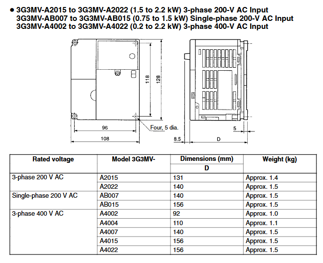
2.2 Comparison Table of Rated Power
This series covers a wide range of power, from 0.1kW to 7.5kW.
200V level (three-phase): from A2001 (0.1kW) to A2075 (7.5kW).
400V level (three-phase): from A4002 (0.2kW) to A4075 (7.5kW).
200V level (single-phase): from AB001 (0.1kW) to AB037 (3.7kW).
Mechanical Installation and Environmental Design
The lifespan of a frequency converter is greatly affected by environmental factors, and a reasonable installation design is a prerequisite for ensuring its long-term stable operation.
3.1 Installation environment requirements
Temperature control: For panel mounted (IP20) models, the ambient temperature should be controlled between -10 ° C and 50 ° C; The closed wall mounted type (NEMA1/IP20) requires a temperature range of -10 ° C to 40 ° C. For models of 5.5kW and above, if the upper and lower cover plates are removed for panel installation, the ambient temperature can be relaxed to 50 ° C.
Cleanliness: Avoid installation in places with direct sunlight, corrosive gases, flammable gases, oil mist, or metal dust. During installation, a protective cover should be covered to prevent metal powder generated by drilling from entering the machine body.
Vibration and impact: Avoid installation in areas with severe vibration.
3.2 Installation direction and spacing
The frequency converter must be installed vertically to ensure heat dissipation.
Side spacing: For models ranging from 0.1 to 4.0 kW, a minimum of 30mm should be retained; 5.5 to 7.5kW models need to retain at least 50mm.
Vertical spacing: A space of at least 100mm must be reserved to facilitate air convection cooling.
Multiple parallel installation: When multiple frequency converters are installed side by side, it is necessary to strictly follow the requirements for side spacing and ensure that cooling fans are installed in the control cabinet to control the internal temperature within the allowable range.
Electrical wiring design
Wiring is the core component of frequency converter applications, and reasonable wiring can effectively suppress interference and prevent misoperation.
4.1 Main circuit terminals
Power input: R/L1, S/L2, T/L3. For single-phase input models (3G3MV-AB series), the power supply is connected to R/L1 and S/L2.
Motor output: U/T1, V/T2, W/T3. Do not connect the power supply to the output terminal incorrectly, otherwise it will burn out the frequency converter.
DC reactor connection:+1 and+2 terminals are used to connect DC reactors (optional) to suppress high-order harmonics.
Braking resistor connection: Terminals B1 and B2 are used to connect external braking resistors, consume regenerative energy, and prevent overvoltage tripping.
Grounding: The grounding terminal must be reliably grounded.
4.2 Control circuit terminals
The control circuit is the bridge for signal interaction, and 3G3MV provides abundant I/O resources.
Digital input (S1-S7):
S1/S2: defaults to forward/reverse command.
S3-S7: Multi functional input terminal, configurable for external faults, fault reset, multi-stage speed commands, jog commands, etc.
SC: Sequential input common terminal.
Analog input:
FR/FC: Frequency command input (0-10V).
CN2 (Pin 1/2/3): Multi functional analog input, supporting voltage (0-10V) and current (4-20mA).
Output terminal:
MA/MB/MC: Multi functional contact output (relay), commonly used for fault alarm.
P1/P2/PC: Multi functional optocoupler output, which can indicate states such as running and consistent frequency.
AM/AC: Multi functional analog output that can monitor output frequency, current, etc.
4.3 Switch Settings
There are DIP switches inside the frequency converter to match different types of control signals:
SW1: Select control input logic. NPN mode (default) or PNP mode. If external power supply is used and the common terminal is connected to the positive pole, it needs to be set to PNP mode.
SW2 Pin 1: RS-422/485 communication terminal resistor selection. The end devices of the communication link need to be set to ON.
SW2 Pin 2: Frequency reference input mode switching. The V side is the voltage input (default), and the I side is the current input.
Digital operator and parameter configuration
The digital operator equipped on 3G3MV is not only used for display, but also has parameter copying function, greatly improving maintenance efficiency.
5.1 Operator button functions
Mode Key: Switch display modes (frequency reference, output frequency, output current, parameter settings, etc.).
Enter Key: Confirm parameter modification.
Increment/Decrement Key: Adjust values or flip pages.
RUN/STOP Key: Local operation and stop control.
FREQ Adjuster: Rotary frequency setting, convenient for on-site debugging.
5.2 Meaning of indicator lights
FREF: Frequency reference setting.
FOUT: Output frequency monitoring.
IOUT: Output current monitoring.
MNTR: Multi functional monitoring (U parameter).
LO/RE: Local/Remote Control Switching. Attention: When the red indicator light is on (such as PRGM mode), the frequency converter will not accept operation instructions after stopping, and special attention should be paid.
PRGM: Parameter Setting Mode. Only some parameters can be modified during operation.
5.3 Parameter Grouping and Key Parameters
The parameters are divided into four groups:
Group 1 (n001-n049): Basic functional parameters.
N001: Parameter writing prohibited/initialized. Set to 8 or 9 to restore factory settings.
N002: Control mode selection (V/f control or vector control).
N003: Selection of running instructions (operator, terminal, or communication).
N036: Motor rated current setting, used for electronic thermal protection.
Group 2 (n050-n079): Terminal function configuration and analog quantity adjustment.
N050-n056: Define the specific functions of S1-S7 terminals (such as multi-stage speed selection, acceleration/deceleration time switching, etc.).
Group 3 (n080-n119): Advanced protection and control parameters.
N080: Carrier frequency setting.
N092-n094: Setting of stall prevention function.
Group 4 (n120-n179): PID control, energy-saving control, and communication parameters.
N128: PID control enabled.
5.4 Parameter copying function
By using the EEPROM inside the operator, parameters can be quickly copied to the same model frequency converter. The steps are as follows:
Set n001=4 (allows reading and writing of all parameters).
Set n177=1 (read allowed).
Set n176=rEd (read parameters to operator).
Move the operator to the new frequency converter and set n176=Cpy (duplicate parameter).
This feature is particularly useful when replacing devices or batch debugging.
Maintenance and troubleshooting
Mastering the meaning of fault codes and troubleshooting methods is the key to reducing downtime.
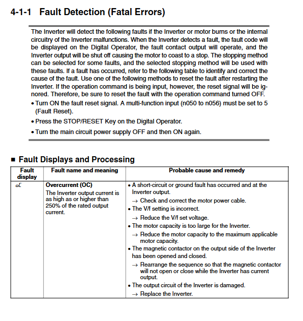
6.1 Fault detection
When a fatal fault occurs, the frequency converter will cut off the output, the motor will stop freely, and the fault contact will act.
OC (Overcurrent): Overcurrent. Usually caused by output short circuit, ground fault, or excessive load. Need to check the motor cables and insulation.
OV (Overvoltage): Overvoltage. The DC voltage of the main circuit is too high. Commonly seen in situations where the deceleration time is too short or the regenerative braking energy of the motor is too high. Need to increase deceleration time or install braking resistors.
UV1 (Undervoltage): Main circuit undervoltage. Check if the power supply voltage is normal and if the wiring terminals are loose.
OH (Overheat): The heat sink is overheated. Check the ambient temperature, load condition, and whether the cooling fan is operating normally.
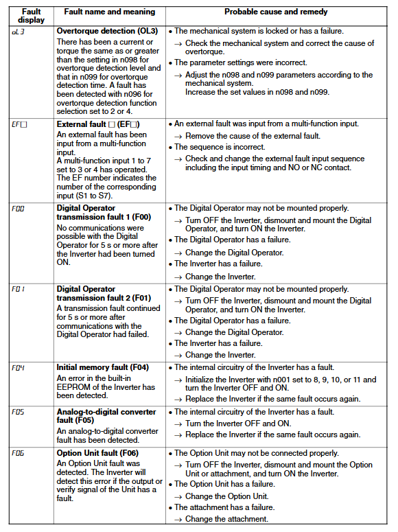
OL1 (Motor Overload): Motor overload. Electronic thermal relay operates. It is necessary to confirm whether the rated current setting of the motor (n036) is correct and whether the load is too large.
OL2 (Inverter Overload): The frequency converter is overloaded. Need to reduce the load or replace the frequency converter with a larger capacity.
6.2 Warning Detection
Non fatal error, the frequency converter will not shut down, but will flash to display a warning.
UV (Main circuit undervoltage): The voltage of the main circuit drops instantly.
OH (Radiation fin overheated): Heat sink overheating warning.
FAN (Cooling fan fault): The cooling fan is stuck or damaged and needs to be replaced.
CE (Communications error): Communication timeout. Check the wiring, baud rate, and terminal resistance settings.
6.3 Maintenance of Cooling Fans
Fans are vulnerable parts, and for models with fans (such as those above 5.5kW), they should be cleaned or replaced regularly according to the usage environment. When replacing, pay attention to the wind direction markings to ensure that the airflow is blowing towards the heat sink.
- YOKOGAWA
- Reliance
- ADVANCED
- SEW
- ProSoft
- WATLOW
- Kongsberg
- FANUC
- VSD
- DCS
- PLC
- man-machine
- Covid-19
- Energy and Gender
- Energy Access
- Renewable Integration
- Energy Subsidies
- Energy and Water
- Net zero emission
- Energy Security
- Critical Minerals
- A-B
- petroleum
- Mine scale
- Sewage treatment
- cement
- architecture
- Industrial information
- New energy
- Automobile market
- electricity
- Construction site
- HIMA
- ABB
- Rockwell
- Schneider Modicon
- Siemens
- xYCOM
- Yaskawa
- Woodward
- BOSCH Rexroth
- MOOG
- General Electric
- American NI
- Rolls-Royce
- CTI
- Honeywell
- EMERSON
- MAN
- GE
- TRICONEX
- Control Wave
- ALSTOM
- AMAT
- STUDER
- KONGSBERG
- MOTOROLA
- DANAHER MOTION
- Bentley
- Galil
- EATON
- MOLEX
- Triconex
- DEIF
- B&W
- ZYGO
- Aerotech
- DANFOSS
- KOLLMORGEN
- Beijer
- Endress+Hauser
- schneider
- Foxboro
- KB
- REXROTH
- YAMAHA
- Johnson
- Westinghouse
- WAGO
- TOSHIBA
- TEKTRONIX
- BENDER
- BMCM
- SMC
- HITACHI
- HIRSCHMANN
- XP POWER
- Baldor
- Meggitt
- SHINKAWA
- Other Brands
- UniOP
- KUKA
- IBA
- Beckhoff
-
Basler Electric DECS-250-CN1SN1N Automatic Voltage Regulator for Generator Excitation Control
-
ADLINK CPCI-6860A - 51-31310-OB10 industrial motherboard CompactPCI SBC
-
ADLINK AmITX-SL-G-H110 - 51-7A104-0A30 Mini-ITX Industrial Motherboard
-
ADLINK PXI-2005-003 - CPCI Industrial PC Data Acquisition Card Multi-Function DAQ
-
ADLINK DININ-814M - 51-14032-0A3D SCSI-100P cable connection Interface Terminal Board
-
ADLINK CPCI-3920NA/C2D15/M1G - 3U CompactPCI Intel Core 2 Duo Single Board Computer
-
ADLINK PCIE-8560 - 51-18014-0A20 Communication Card High Speed DAQ
-
ADLINK PCI-C154+ - Motion Control Card 4-axis Motion Controller Board
-
ADLINK PCI-RTV24 - image capture card Analog Video Frame Grabber
-
ADLINK NuPRO-842LV/P - 51-41360-0B30 Industrial Motherboard CPU Board
-
ADLINK cBP-3208/3208R - CPCI Board 3U 8-Slot CompactPCI Backplane
-
ADLINK PCI-8164 - 4-Axis Motion Controller PCI Card 51-12406-0A40
-
ADLINK PCIe-GIE64+ - 4-CH GigE Vision PoE+ Frame Grabber Video Capture Card
-
ADLINK CPCI-6860 / 6860A - CompactPCI Dual Xeon Single Board Computer
-
ADLINK IEC-915GV - REV 1.1 Industrial motherboard CPU Board
-
ADLINK ND-6520 - Technology RS-232 to RS-422RS-485 Converter NuDAM Module
-
ADLINK RTV-24 / PCI-MP4S - 51-12519-1C30 4-Channel Real Time Video Capture Board
-
ADLINK cPCI-6910 / cPCI-6910AM/M1G - cPCI-6910AM/DXL16/M1G/S80G(G)-3120 BOARD CompactPCI SBC
-
ADLINK NUPRO-A40H - Linghua 51-41807-1A30 Industrial Control Computer Motherboard
-
ADLINK USB-3488A - USB to GPIB INTERFACE USB-3488A(G) Controller Module
-
ADLINK PCI-8134A - motion control card 4-Axis Controller Card
-
ADLINK PCI-7432 - Board 32-Channel input / 32-output Isolated Digital I/O PCI Card
-
ADLINK PCI-8134A - 51-12421-0A10 motion controller card tested
-
ADLINK LPCIe-7230 - 32 CH Isolated Input/output Card 2 Interrupts Low Profile PCIe
-
ADLINK NuPRO-E340 - industrial computer motherboard 51-47807-0A30 PICMG 1.3 SHB
-
ADLINK PCI-7434 - High-speed Digital Acquisition Card 64-CH Isolated DO Card
-
ADLINK NuPRO-E330 - 51-41805-0A20 Indsutrial Board SHB Single Board Computer
-
ADLINK PCI-7248 - OPTO-22 48 CHANNEL DIO DIGITAL TTL/DTL I/O 51-12006-0A40 GP
-
ADLINK PCI-8134 - Motion control card 4-Axis Controller Card
-
ADLINK AMP-208C - Movimiento Control Tarjeta 51-12420-1A20 W/Expansión & Breakout
-
ADLINK PCI-8164 - 51-12406-0A40 PCB Board 4-Axis Motion Controller Card
-
ADLINK DIN-68Y-SGII / DIN-68M-J3A - Terminal Board Connector Interface Block
-
ADLINK PCIe-7432 - Technology 51-18402-0A10 PCIe Card With High Input Range
-
ADLINK PCI-8144 / PCI-8144N - Motion control card 4-Axis Stepper Controller Card
-
ADLINK HSL-HUB3/REPEATER - HIGH SPEED LINK EXTENSION MODULES Distributed Hub Module
-
ADLINK ND-6017 - Data Logging + Acquisition 8CH A/D input Mod NuDAM Module
-
ADLINK LPCIe-7250 - data acquisition card Low Profile 8-CH Relay Output Card
-
ADLINK PCI-7432 - I/O card 64-CH Isolated Digital Input Output PCI Card
-
ADLINK IMB-M43H - industrial control computer motherboard Q87 Chip Micro-ATX
-
ADLINK MP-C154 - Motion control Card 4-Axis Motion Controller Board
-
ADLINK PCI-RTV24 - image capture card Video Frame Grabber Card
-
ADLINK PCI-7250 - 8-CH Relay Output & 8-CH Isolated DI Card
-
ADLINK PCI-6308V - 8-CH 12-Bit Isolated Analog Output PCI Card PCB-I-E-1148=6EX2
-
ADLINK PCI-7248 - capture card 48-CH Opto-22 Compatible DIO Card
-
ADLINK HSL-AI16A02-M-VV - Analog Input Output Distributed Module
-
ADLINK NuPRO-A301 - Rev:1.4 NUPRO-A301 PICMG Full-Size Single Board Computer
-
ADLINK PCI-6208V-GL - 8-CH Voltage Analog Output PCI Card
-
ADLINK PCI-8134A - 51-12421-0A10 4-Axis Motion Controller Card
-
ADLINK MNET-S23 - TECHNOLOGY MNET S23 - SERVO DRIVER CONTROL MODULE
-
ADLINK M-342 - ATX I3 I5 I7 Q67 Industrial Motherboard
-
ADLINK NUPRO-780 - Industrial Motherboard CPU Board PICMG SBC
-
ADLINK MP-C154 / MP-C152 - 4-Axis Motion Control Card Pulse-Train Controller
-
ADLINK NuPRO-935A/LV10B0 - Motherboard 51-41802-0A10 GP w/RAM Industrial Control Board
-
ADLINK MP-C154 - Motion control card 4-Axis Motion Controller Mainboard
-
ADLINK PCI-7250 - PCI Acquisition Card 8-CH Relay Output Isolated DI Card
-
ADLINK ACL-7124 - Technology Inc.24 DIO Card Digital Input Output Card
-
ADLINK PCI-8554 A2 - Timer/Counter Data Acquisition Card
-
ADLINK DIN-825-GP4 - Terminal Block Interface Board Breakout Module
-
ADLINK NuPR0-761 - REV:1.1 Industrial motherboard Full-Size PICMG SBC
-
ADLINK MXE-1401/M8G (G) - Matrix Fanless Embedded Computer Industrial PC
-
ADLINK HSL-DI16DO16-UD-NN - Digital 16 Channel I/O Mod Distributed I/O Module
-
ADLINK ND6520 - NUDAM INTELLIGENT DA&C MODULE RS232-RS-422/RS485 CONVERTOR
-
ADLINK NUPRO-761 - REV:1.1 Industrial Motherboard CPU Board
-
ADLINK AMP-208C - Motion Control Card 51-12420-1A20 DSP-based 8-axis
-
ADLINK NuPRO-A301REV 1.4 - with packaging industrial computer motherboard PICMG SBC
-
ADLINK PCM-9112+ - 51-12300-0A2 industrial motherboard Multi-Function DAQ PC/104 Module
-
ADLINK PCM-7250+ - 8-CH Relay Outputs & 8-CH Isolated DI Module PC/104
-
ADLINK PCI-RTV24 - Image capture card Analog Video Frame Grabber
-
ADLINK PCI-8134 - Motion Controller PCI Card 4-Axis Controller Board
-
ADLINK PCI-7432 - Isolated Digital I/O PCI Card
-
ADLINK PCI-8554 A2 - acquisition card Timer/Counter Card
-
ADLINK PCI-8132 - Rev.A2 2-Axis Servo & Stepper Motion Controller Card
-
ADLINK PCI-8132 - Data Acquisition card 2-Axis Motion Controller Card
-
ADLINK EBP-13E4 - 51-46703-0A30 Industrial Backplane Board Passive Backplane
-
ADLINK PCI-800L - Electronic Card Interface Controller Card
-
ADLINK PCIe-GIE72 - 51-18531-0A10 PCB Board GigE Vision Frame Grabber
-
ADLINK DAQ-2010(G)-OOBO - Simultaneous-Sampling Multi-Function DAQ Card
-
ADLINK PCI-9112 - REV.B1 Multifunction DAQ Card Data Acquisition Card
-
ADLINK PCI-7230 - 51-12003-DA60 32-CH Isolated Digital I/O Card
-
ADLINK PCI-7432 - Data Acquisition Card Isolated Digital I/O PCI Card
-
ADLINK ETX-AT-N270-18/LXE - 51-71111-0A20 ETX CPU Module Motherboard
-
ADLINK HSL-DI32-UD-N - DIGITAL INPUT 32 POINTS MODULE Distributed I/O
-
ADLINK AMP-204C - Motion Control card DSP-Based 4-Axis Advanced Controller
-
ADLINK MNET-4XMOG-0050 - Four-axis Motion Controller Distributed Motion Module
-
ADLINK AMP-204C - Motion control card DSP-Based 4-Axis Pulse-Train Controller
-
ADLINK PCI-7442 - Switch card 64-Channel Datalogging & Acquisition Card
-
ADLINK M-302 - Industrial control motherboard ATX PC Board
-
ADLINK NUPRO-852 / NUPRO-852LV - Industrial motherboard Single Board Computer
-
ADLINK PCI-8134 - REV.B1. 4-Axis Motion Controller Card
-
ADLINK PCI-GIE62 + - 51-18502-0A20 2-CH GigE Vision Frame Grabber PoE Card
-
ADLINK PCI-MPG24 - 51-12523-0B20 MPEG4 Card Video Compression Hardware
-
ADLINK HSL-TB32-M-DIN - 32-CH I/O TERMINAL W/ HSL-AI16AO2-M-VV MODULE
-
ADLINK PCI-M114-GL - PCB Ver 2.1 Motion Controller Axis Card
-
ADLINK IMB-M40H - SYM76996H61 motherboard Industrial Computer Mainboard
-
ADLINK NUPRO-A40H - 51-41807-1A20 industrial control motherboard H61 Chip
-
ADLINK PCI-M114-GL - Axis Card Data Acquisition Card PCB VER2.2 Motion Controller
-
ADLINK PCI-8134 - Motion Controller PCI Card 4-Axis Controller Board
-
ADLINK PCI-8102 - Motion control card 2-Axis Servo & Stepper Controller
-
ADLINK NuPRO-841REV:3.0 - motherboard Industrial Control PC Board
-
ADLINK HSL-TB32-U-DIN REV A1 - Breakout Terminal Board Field I/O Module
-
ADLINK AMP-204C - Motion Control card DSP-Based 4-Axis Pulse-Train Controller
-
ADLINK NUPRO-A40H - 51-41807-1A20 industrial control motherboard H61 PC Board
-
ADLINK PCI-6308A / PCI-6308V - 51-12202-0A50 Isolated Analog Output Card
-
ADLINK AMP-204C - DSP-Based 4-Axis Advanced Pulse-Train Motion Controller
-
ADLINK PCI-7434 - Technology 64-Channel Isolated Digital I/O PCI Cards
-
ADLINK CPCI-6840 / CPCI-6840V / PM16/M1G-12G0 - CompactPCI Single Board Computer CPU Module
-
ADLINK PCIE-GIE74 - Motherboard Video Capture Card 51-18531-0A10 Frame Grabber
-
ADLINK NuPRO-E330 - industrial computer equipment motherboard Control Mainboard
-
ADLINK AMP-208C / 51-12420-1A20 - Motion Control Card W/ Expansion & Breakout Board
-
ADLINK HPCI-14S12U - industrial computer baseboard Passive Backplane 14 Slots
-
ADLINK PCI-8164 - 4-Axis Motion Controller PCI Card W/ 1x Cable, 1x Breakout Box
-
ADLINK PCIe-RTV24 - 51-18016-0A20 Image Acquisition Video Capture Card
-
ADLINK M-342 - 5 PCI ATX Motherboard Industrial PC Mainboard
-
ADLINK PCI-FIW64 - 4/2 Channel IEEE1394B Image Capture Card FireWire Frame Grabber
-
ADLINK PCI-7432 - digital IO card 64-CH Isolated Digital Input Output Card
-
ADLINK 51-12001-0C20 - Circuit Board PCI-7200 Data Acquisition Controller Card
-
ADLINK PXI-3920 - PXI 3U cPCI Industrial Controller Embedded System CPU Board
-
ADLINK NuPRO-841REV:2.0 - motherboard Industrial Control PC Board
-
ADLINK NuPro-E330 - 51-41805-0A20 PCB Industrial Control Computer Motherboard
-
ADLINK PCI-RTV24 - Image capture card Analog Video Frame Grabber
-
ADLINK PCI-7442 - Switch card 64-Channel Datalogging & Acquisition Card
-
ADLINK HPX-13S4 - device baseboard Passive Backplane Riser Card
-
ADLINK PCI-9112 REV A.1 - Multi Function DA&C Board Data Acquisition Card
-
ADLINK PCI-7248 - 51-12006-0A40 Card Control 48-CH Digital I/O Module
-
ADLINK CPCI-6860 / 6860A - motherboard CompactPCI Dual Xeon Single Board Computer
-
ADLINK DPAC-3020-11(G) - Embedded PC Automation Controller Machine Control Board
-
ADLINK NuPRO-841 REV:1.0 - industrial control motherboard CPU Board
-
ADLINK MNET-4XMOG-0050 - Four-axis Motion Controller MNET Motion Control Card

K-JIANG

Add: Jimei North Road, Jimei District, Xiamen, Fujian, China
Tell:+86-15305925923