
K-WANG


TRICON ®/ Installation and maintenance of E/E2/E3 transmitters
TRICON ®/ Installation and maintenance of E/E2/E3 transmitters
Product Overview
core functionality
For Neptune ® The series of water meters provide electronic interfaces for water consumption monitoring and support various process controls based on water consumption, which can be integrated with SmartTrol ® Integrate controllers or third-party instrument devices to build complex measurement and monitoring systems.
Product Model and Classification
Divided by signal type
Digital Pulse
Basic model: 3-terminal design, outputting electrical pulses corresponding to water flow rate, requiring 12-24VDC power supply, suitable for scenarios that only require digital signals.
E2/E3 models: 5-terminal design, retaining basic features, new high-resolution output terminal and counting direction terminal, supporting high-speed bidirectional counter connection, also requiring 12-24VDC power supply, suitable for high-resolution digital signal demand scenarios.
Adaptation types: divided into two categories: Disc specific and Turbine specific, which can adapt to all Neptune disc or turbine watches.
Simulate 4-20mA type
5-terminal design, with digital pulse type basic functions, providing additional 4-20mA analog signal output proportional to water flow rate, requiring 24VDC power supply, suitable for scenarios that require both analog and digital signals.
Adaptation requirements: Strictly match the size and type of the water meter, confirm the compatible model when purchasing, and contact the manufacturer for technical support if necessary.
Special Model Description
The TRICON/E3 transmitter is not submersible and is not recommended for pit installation scenarios.
The T-8 disc gauge has been discontinued. Currently, all TRICON/E transmitters compatible with disc gauges are T-10 type. When compatible with T-8 gauges, it may not be possible to achieve a 20mA output level. The relevant values are only for calibration reference.
Key technical parameters
environmental conditions
Working temperature: 0 ° C~70 ° C (32 ° F~158 ° F)
Storage temperature: -40 ° C~85 ° C (-40 ° F~185 ° F)
Working humidity: 0~95% RH, no condensation
Electrical specifications (classified by model)
Pulse output (working temperature 0-70 ° C)
Low level output voltage (Vol): typical value 0.4V
High level output voltage (Voh): minimum value 8.5V, maximum value 12V, typical value is the power supply voltage minus 1.0V
Low level output current (Iol): typical value -10mA
High level output current (Ioh): typical value+10mA
Output rise time (tr l-h): maximum value 2 μ S (RL=2.4K Ω, CL=50pF)
Output decay time (tf h-l): maximum value 2 μ S (RL=2.4K Ω, CL=50pF)
4-20mA model (working temperature 0-50 ° C)
Power supply voltage (VCC): 22.5~26.5VDC
Power supply current (IS): 20~80mA
Loop resistance (RL): 0~600 Ω
Range accuracy (Gain): maximum 0.5% FS
Zero offset accuracy (Zero): maximum 0.2% FS
The digital pulse output parameters are consistent with the pulse output model
HF and UP/DN models (working temperature 0-70 ° C)
Power supply voltage (VCC): 11.5~26.5VDC
Power supply current (IS): 20~50mA
Low level output voltage (Vol): maximum value 0V
High level output voltage (Voh): typical value 24V, maximum value 26.5V
Low level output current (Iol): minimum value -1.0A
High level output current (Ioh): typical value 0.04A, maximum value 1.0W/Voh
Output rise/fall time: maximum value 2 μ S (RL=2.4K Ω, CL=50pF)
Absolute limit values for all models
Working temperature: 0~85 ° C
Storage temperature: -40~85 ° C
Power supply voltage: -30~30V
Pulse output load resistance: minimum 1200K Ω
Pulse output current: maximum 10mA
Note: Exceeding the above limit values may result in equipment damage
Performance data (classified by water meter type)
T-10 Disk Watch
Water meter size (inches) Maximum flow rate (gpm) Continuous maximum flow rate (gpm) Minimum flow rate (gpm) Number of pulses per gallon Maximum flow rate Pulse output (Hz) 4-20mA Output flow range (gpm)
⅝ 20 10 ¼ 578.10 192.70 0–20
¾ 30 15 ½ 322.60 161.30 0–30
1 50 25 ¾ 150.80 125.67 0–50
1½ 100 50 1½ 67.57 112.62 0–100
2 160 80 2 37.30 100.00 0–160
Note: The high-resolution output of TRICON/E2 requires multiplying the number of pulses per gallon and the maximum flow pulse output value by 36, and E3 requires multiplying by 40
T-8 Disc Watch (discontinued)
Water meter size (inches) Maximum flow rate (gpm) Continuous maximum flow rate (gpm) Minimum flow rate (gpm) Number of pulses per gallon Maximum flow rate Pulse output (Hz) 4-20mA Output flow range (gpm)
⅝ 20 10 ¼ 473.60 157.87 0–24.41
¾ 30 15 ½ 329.14 164.57 0–29.40
1 50 25 ¾ 126.55 105.46 0–59.58
1½ 100 50 1½ 47.86 79.77 0–141.18
2 160 80 2 25.60 68.27 0–234.37
Note: The high-resolution output coefficient is the same as the T-10 table; When the T-10 transmitter is adapted to the T-8 meter, the theoretical flow rate corresponding to the 20mA output is greater than the maximum allowable flow rate of the water meter, which cannot be achieved in actual operation
Trident ® Turbine gauge (TT)
Water meter size (inches) Continuous maximum flow rate (gpm) Minimum flow rate (gpm) Pulses per gallon Maximum flow rate Pulse output (Hz) 4-20mA Output flow range (gpm)
2 200 3 4.6080 15.36 0–200
3 450 5 2.8900 21.68 0–450
4 1000 10 1.5900 26.50 0–1000
6 2000 20 0.4640 15.47 0–2000
8(S/N≤31918014) 3500 35 0.2493 14.54 0–3500
8(S/N≥31918274) 3500 35 0.2253 13.14 0–3873
10(S/N≤31919282) 5500 50 0.1600 14.67 0–5500
10(S/N≥31919300) 5500 50 0.1472 13.49 0–5981
Note: E2 high-resolution output requires multiplying the number of pulses per gallon and the maximum flow pulse output value by 9, while E3 requires multiplying by 10
High Performance Turbine Meter (HPT)
Water meter size (inches) Continuous maximum flow rate (gpm) Minimum flow rate (gpm) Pulses per gallon Maximum flow rate Pulse output (Hz) 4-20mA Output flow range (gpm)
1½ 160 4 6.09500 16.25 0–160
2 200 4 6.09500 20.32 0–200
3 450 5 11.20000 84.00 0–450
4 1200 10 7.55600 151.1 0–1200
6 2500 20 0.72730 30.30 0–3000
8 4000 35 0.75560 50.37 0–4000
10 6500 50 0.75560 81.86 0–6500
12 8000 120 0.75560 100.75 0–8000
16 13500 200 0.07556 17.00 0–13500
20 22000 300 0.07556 27.71 0–22000
Note: The high-resolution output coefficient is the same as Trident's ® Turbine watch
Compound Meters
Core composition: Composed of a combination of turbine components and disk components, the components of different models of composite watches are matched differently (such as 3 "TRU/FLO consisting of 3" TT turbine components and ⅝ "T-10 disk components).
Performance reference: It is necessary to separately refer to the performance specifications of the corresponding turbine components and disc components. The 4 "/6"/8 "/10" HP TECTUS III turbine components have dedicated performance parameter tables.
Installation process
Pre-installation preparation
Tools and Materials
Essential tools: Medium sized flathead screwdriver, wire stripping pliers, hammer, ⅛ "diameter punch (or similar tools).
Essential material: # 22 AWG multi-core solid copper wire.
Optional material: Dow Corning ® # 4 moisture-proof compounds (or equivalent products).
Inspection and Storage
After unboxing, check whether the transmitter components (including the transmitter body, terminal cover, and installation ring) are intact, without damage or missing.
Before installation, the components need to be stored in a clean and dry environment, with a temperature maintained between -40 ° C and 85 ° C.
Safety and wiring specifications
Avoid placing instrument circuits near electrical noise sources such as contactors, motor starters, radio transmitters, and high-voltage power lines.
Separate the wiring of instrument circuits from other circuits and prioritize the use of independent metal conduits or metal cable trays; Long distance cabling (up to 1000 feet) requires # 22 AWG shielded twisted pair cables, with the shielding layer only grounded at the receiving device end.
When wiring needs to intersect, maintain a right angle intersection to reduce noise coupling; Use dedicated power sources (such as independent circuit breakers, isolation transformers) to ensure grounding in accordance with local electrical regulations.
Specific installation steps
1. Wiring operation
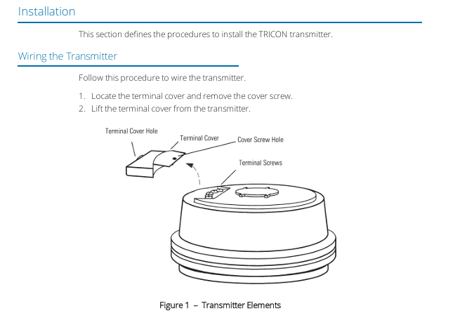
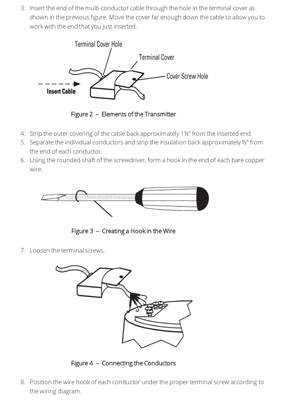
Unscrew the terminal cover screws, remove the terminal cover, thread the multi-core cable through the hole on the terminal cover, and move the terminal cover down along the cable to a convenient operating position.
Peel off the outer sheath of the cable by about 1.5 inches, separate the core wires and strip off the insulation layer of each core wire by about 0.5 inches. Use a screwdriver with a round handle to bend the bare copper wire into a hook shape.
Loosen the terminal screw of the transmitter, and wrap the hooks of each core wire clockwise around the corresponding terminal screw according to the wiring diagram (ensuring that the insulation layer is not pressed under the screw), and tighten the screw firmly (avoiding over tightening).
2. Wiring code (divided by pins)
Pin number TRICON ®/ E digital pulse type (before January 1996) TRICON ®/ E2/E3 digital pulse type (after January 1996) TRICON ®/ E/E2/E3 4-20mA type
1 connectionless high-resolution output 4-20mA source (+)
2 unconnected counting direction (ground contact closed, powered by pull-up resistor) 4-20mA return (-)
3 12-24VDC power input (+) 12-24VDC power input 24VDC power input (+)
4 Public Grounding (-) Public Grounding (-) Public Grounding (-)
5 pulse output pulse output pulse output
Note: The typical value of the pull-up resistor is 2K Ω for every 5VDC; "+" indicates that the regular current flows out of the transmitter.
3. Line testing
Connect the transmitter power and verify the output signal according to the following standards:
When there is no flow: there is no pulse at the digital output terminal, and the 4-20mA circuit current is 4mA.
At half flow rate: the pulse frequency of the digital output terminal is 1/2 of the maximum pulse frequency, and the 4-20mA circuit current is 12mA.
At maximum flow rate: The pulse frequency of the digital output terminal is equal to the maximum pulse frequency, and the 4-20mA circuit current is 20mA.
4. Final assembly
Turn off all power and apply sufficient Dow Corning on exposed wires and terminals ® # 4 compounds, the interior of the terminal cover is also filled with this compound (for moisture resistance).
Reset the terminal cover, tighten the fixing screws (to avoid over tightening), fasten the stress relief accessory onto the cable and push it into the cable entry hole, and wipe off excess compound.
5. Installation of transmitter
If the water meter has installed a register: align the punch with the center of the sealing pin at the bottom of the register, strike with a hammer to break the pin head, and rotate the register counterclockwise by 1/4 turn to remove it.
Install the TRICON transmitter on the water meter and rotate clockwise to lock it; Place the register mounting ring (with four sets of circular grooves facing upwards) on top of the transmitter, align it with the notch on the transmitter terminal cover, and tighten it.
Place the register on the transmitter and mounting ring, rotate clockwise until locked; Insert the new sealing pin into the register base and transmitter base to prevent tampering.
Maintenance and troubleshooting
Core scenarios for troubleshooting
When the electronic flow indication is inconsistent with the mechanical register indication, follow the following steps to troubleshoot:
Abnormal handling measures for items to be verified
Whether the size and type of the transmitter, register, and water meter match, replace them with transmitters or registers that are compatible with the water meter
Does the register rotate smoothly after being installed on the transmitter? Replace or repair the register to solve the problem of excessive torque
Whether the transmitter wiring and power supply are correct, correct wiring errors, and troubleshoot power supply faults
Adjust and calibrate the compatibility and calibration status of the transmitter connection device as required
- YOKOGAWA
- Reliance
- ADVANCED
- SEW
- ProSoft
- WATLOW
- Kongsberg
- FANUC
- VSD
- DCS
- PLC
- man-machine
- Covid-19
- Energy and Gender
- Energy Access
- Renewable Integration
- Energy Subsidies
- Energy and Water
- Net zero emission
- Energy Security
- Critical Minerals
- A-B
- petroleum
- Mine scale
- Sewage treatment
- cement
- architecture
- Industrial information
- New energy
- Automobile market
- electricity
- Construction site
- HIMA
- ABB
- Rockwell
- Schneider Modicon
- Siemens
- xYCOM
- Yaskawa
- Woodward
- BOSCH Rexroth
- MOOG
- General Electric
- American NI
- Rolls-Royce
- CTI
- Honeywell
- EMERSON
- MAN
- GE
- TRICONEX
- Control Wave
- ALSTOM
- AMAT
- STUDER
- KONGSBERG
- MOTOROLA
- DANAHER MOTION
- Bentley
- Galil
- EATON
- MOLEX
- Triconex
- DEIF
- B&W
- ZYGO
- Aerotech
- DANFOSS
- KOLLMORGEN
- Beijer
- Endress+Hauser
- schneider
- Foxboro
- KB
- REXROTH
- YAMAHA
- Johnson
- Westinghouse
- WAGO
- TOSHIBA
- TEKTRONIX
- BENDER
- BMCM
- SMC
- HITACHI
- HIRSCHMANN
- XP POWER
- Baldor
- Meggitt
- SHINKAWA
- Other Brands
- UniOP
- KUKA
- IBA
- Beckhoff
-
ADLINK CPCI-6860A - 51-31310-OB10 industrial motherboard CompactPCI SBC
-
ADLINK AmITX-SL-G-H110 - 51-7A104-0A30 Mini-ITX Industrial Motherboard
-
ADLINK PXI-2005-003 - CPCI Industrial PC Data Acquisition Card Multi-Function DAQ
-
ADLINK DININ-814M - 51-14032-0A3D SCSI-100P cable connection Interface Terminal Board
-
ADLINK CPCI-3920NA/C2D15/M1G - 3U CompactPCI Intel Core 2 Duo Single Board Computer
-
ADLINK PCIE-8560 - 51-18014-0A20 Communication Card High Speed DAQ
-
ADLINK PCI-C154+ - Motion Control Card 4-axis Motion Controller Board
-
ADLINK PCI-RTV24 - image capture card Analog Video Frame Grabber
-
ADLINK NuPRO-842LV/P - 51-41360-0B30 Industrial Motherboard CPU Board
-
ADLINK cBP-3208/3208R - CPCI Board 3U 8-Slot CompactPCI Backplane
-
ADLINK PCI-8164 - 4-Axis Motion Controller PCI Card 51-12406-0A40
-
ADLINK PCIe-GIE64+ - 4-CH GigE Vision PoE+ Frame Grabber Video Capture Card
-
ADLINK CPCI-6860 / 6860A - CompactPCI Dual Xeon Single Board Computer
-
ADLINK IEC-915GV - REV 1.1 Industrial motherboard CPU Board
-
ADLINK ND-6520 - Technology RS-232 to RS-422RS-485 Converter NuDAM Module
-
ADLINK RTV-24 / PCI-MP4S - 51-12519-1C30 4-Channel Real Time Video Capture Board
-
ADLINK cPCI-6910 / cPCI-6910AM/M1G - cPCI-6910AM/DXL16/M1G/S80G(G)-3120 BOARD CompactPCI SBC
-
ADLINK NUPRO-A40H - Linghua 51-41807-1A30 Industrial Control Computer Motherboard
-
ADLINK USB-3488A - USB to GPIB INTERFACE USB-3488A(G) Controller Module
-
ADLINK PCI-8134A - motion control card 4-Axis Controller Card
-
ADLINK PCI-8134 - 51-12403-0B20 PCB Board Motion Controller Card
-
ADLINK LPCI-3488A - PCI Card 51-12801-0A30 Low Profile IEEE-488 GPIB Card
-
ADLINK NUPRO-900A - industrial computer motherboard Single Board Computer
-
ADLINK cPCI-6840V - industrial control motherboard CompactPCI SBC
-
ADLINK M-342 - industrial motherboard ATX Mainboard
-
ADLINK NUPRO-935A/LV - industrial control motherboard
-
ADLINK cPCI-3538 - CompactPCI Async Serial Communications Module
-
ADLINK PCI-1610 - Card 4-Port RS-232 PCI Serial Communication Card
-
ADLINK HSL-DI32-DB-N - Distributed I/O Module 32-CH Digital Input
-
ADLINK CPCI-6860A - motherboard E7501 CompactPCI Single Board Computer
-
ADLINK PCI-8134A - 4-Axis Motion Control Card PCB Board
-
ADLINK EURESYS LINK - grabbers Video Capture Card Frame Grabber
-
ADLINK NuPRO-965DV - motherboard Industrial Control Board
-
Thermo Fisher Scientific 80100-60500 - 80000-61010R 80000-21000R 80000-60457 Spectrum System Controller ADLINK Components
-
ADLINK PCI-7296 - IO card High Density 96-CH Opto-Isolated DIO Card
-
ADLINK MXC-6322D - Matrix Industrial Computer Fanless Embedded PC
-
ADLINK DIN-825-GP4 - connector board Terminal Block Interface
-
ADLINK AMP-208C - Motion Control Card DSP-based 8-axis
-
ADLINK PCIe-GIE72 - 51-18531-0A10 2-CH GigE Vision Frame Grabber PoE+ Card
-
ADLINK PXIS-3320 - PXI/PXIe Chassis 15-slot 6U PXI/CompactPCI SEM-I-1518=9N41
-
ADLINK MI-965 - Industrial CPU Motherboard
-
ADLINK M-302 - Industrial control motherboard
-
ADLINK PCI-6308V - 51-12202-0A50 Isolated Analog Output Card PCB-I-E-1813=ZA03
-
ADLINK NUPRO-935A - Industrial Mother Board CPU Board
-
ADLINK PCI-7434 - PLOTECH Digital Output Card PCB-I-E-1182=6EX2
-
ADLINK PCI-7432 - 64 Channel Isolated Digital I/O PCI CARD
-
ADLINK NUPRO-935A/DV - 51-41802-0A10 motherboard Industrial Control Board
-
ADLINK PCIe-GIE72 - 51-18531-0A10 2-CH GigE Vision Frame Grabber PoE+ Card
-
ADLINK HSL-DI16DO16-M-NN - HSL-DI16DO16-M-NN(G)-0280 Discrete I/O Module Distributed I/O
-
ADLINK cPCI-6760D / cPCI-6840V - cPCI Single Board Computer Industrial Motherboard
-
ADLINK NuPRO-A301 - Motherboard IPC Motherboard
-
ADLINK NuPRO-935A/LV - motherboard Industrial Control Board
-
ADLINK NUPRO-E320LV - motherboard Industrial Control Board
-
ADLINK NuPRO-E42 - Industrial Control Board Motherboard
-
ADLINK M-342 - ATX Motherboard Industrial PC Mainboard
-
ADLINK CPCI-6860 / 6860A - Industrial Control Motherboard CompactPCI SBC
-
ADLINK AmITX-SL-G-Q170/GEHC(EA)-021E - 51-7A104-0A20 Industrial Motherboard w/ DDR4
-
ADLINK NUPRO-852 / NUPRO-852LV - industrial control motherboard
-
ADLINK DAQ-2006-004 - Multi-Function DAQ Cards Data Acquisition
-
ADLINK PCIe-RTV24 - Frame Grabbers Video Capture Cards PCI-e x1 4-CH 120fps
-
ADLINK PCI-8134 - 51-12403-0B20 4-Axis Motion Controller Card
-
ADLINK PCI-8132 - 2-Axis Motion Controller Card
-
ADLINK cBP-6402 - Backplane Passive Backplane
-
ADLINK cPCI-6760D - cPCI Single Board Computer Industrial Control Motherboard
-
ADLINK DIN-825-4PO(G)-0030 - Terminal Board Motion Control Breakout Board
-
ADLINK M-322 - Industrial Motherboard
-
ADLINK ABX-1301 - 51-63808-0A20 Industrial Motherboard
-
ADLINK PCI-7433 - 64-CH Isolated Digital Input Card
-
ADLINK AMP-208C - Motion Control card
-
ADLINK DIN-50S-01 - TECHNOLOGY TERMINAL BLOCK INTERFACE MODULES W/ DIN RAIL
-
ADLINK PCI-8134 - 51-12403-0B20 4-Axis Motion Controller Card
-
ADLINK MXE-201/MSSD64G - Technology Automation Computer Fanless Embedded System
-
ADLINK USB-3488A (G) - USB to GPIB CARD Controller Interface
-
ADLINK cPCI-3720L2 - SBC Single Board Computer PCB AMAT 0190-14599
-
ADLINK PCI-7251 - Relay Output Board Expansion Module
-
ADLINK PCI-8124-C - PCB Board 4-CH Encoder Trigger Card
-
ADLINK HD636 - Industrial Computer Board PCB-I-E-2200=9L32-2 Main Board
-
ADLINK USB-3488A - THERMOTRON INDUSTRIES IEEE 488 CPU INTERFACE WITH USB/GPIB
-
ADLINK MI-965 - motherboard Industrial CPU Board
-
ADLINK LPCIe-7250 - Technology Digital IO card Low Profile PCIe Relay Output
-
ADLINK NuPro-720/SCOPUS - Technology With 256MB Industrial MotherBoard
-
ADLINK NuPR0-840 - industrial control motherboard
-
ADLINK M-342 - Motherboard ATX PC Mainboard
-
ADLINK MI-965 - motherboard Industrial CPU Board
-
ADLINK CPCI-6530V/4402E/M4G - AMAT CPCI-6503VED/4402E/M4-0/SD64G-2550 Universal SBC
-
ADLINK IMB-M43-IRV - Industrial Motherboard ATX PC Board
-
ADLINK 52983 / 58183 - Chroma PXI I/O Input/Output Card + Carrier Adapter
-
ADLINK PXI-3920 - PXI 3U cPCI Industrial Controller w/ RAM SSD Embedded CPU
-
ADLINK NuPRO-842LV/P - motherboard Industrial Control PC Board
-
ADLINK PCI-7442 - 64-Channel Datalogging Acquisition Switch Card
-
ADLINK PCIe-RTV24 - Cadre Agrippeurs Vidéo de Capture Cartes Pci-E x1 4-CH
-
ADLINK ACL-7122A - TECHNOLOGY 51-11004-1A1 CIRCUIT BOARD 96-CH DIO Card
-
ADLINK PCIe-RTV24 - 51-18016-0A20 Image Acquisition Video Capture Card
-
ADLINK AMP-204C - DSP-Based 4-Axis Advanced Pulse-Train Motion Controller
-
ADLINK 52981 / 58183 - Chroma PXI Digital I/O DIO Input/Output Card + Carrier Adapter
-
ADLINK PCI-8102 - motion control card 2-Axis
-
ADLINK NuPRO-E320LV - industrial computer motherboard
-
ADLINK PCI-RTV24 - card Analog Video Capture Frame Grabber
-
ADLINK M-302 - Motherboard P/N: 08GSAQ96501102
-
ADLINK NEON-1020 - Smart camera Industrial Machine Vision
-
ADLINK AMP- 208C - card DSP-based 8-axis Motion Controller
-
ADLINK PCI-9114DG - Multi-Function Daq Card Data Acquisition
-
ADLINK MXC-6322D/BE_FanG) - Matrix PM2-MXC Fanless Embedded Computer
-
ADLINK DIN-825-4P0 - Terminal Board Motion Control Breakout Board
-
ADLINK HPCI-8S4 REV.B2 - Industrial Control Base Plate Passive Backplane
-
ADLINK HSL-DI32-DB-N - Distributed I/O Module 32-CH Digital Input
-
ADLINK NuPRO-935A/DV - industrial control motherboard
-
ADLINK PCI-7442 - Switch card 64-CH Datalogging Acquisition Card
-
ADLINK NuPRO-E42 - motherboard 51-41808-0A30 Industrial Motherboard
-
ADLINK CPCI-3610D/N45/M1G(G)-10B0 - CompactPCI Intel Atom Single Board Computer CPU Board
-
ADLINK LPCI-7250 - GP Output Isolated Digital Input Card PCB 51-12803-0A10
-
ADLINK PCI-7250 - 51-12007-0A40 PCI7250 8-CH Relay Output & 8-CH Isolated DI Card
-
ADLINK STC-1005 - 10.4inch touch panel PC E3845 CPU
-
ADLINK PCI-FIW64 - image card FireWire Frame Grabber
-
ADLINK NuPRO-935A/LV - industrial computer motherboard
-
ADLINK PCI-8164 00B0 - Centralized Motion Controller 4-axis PCB-I-E-1179=6EX2
-
ADLINK ACLD-9137F REV A1 - 51-14006-101 Screw Termination Board
-
ADLINK PCI-7248 - 51-12006-0A40 Control Card Digital I/O
-
ADLINK HPCI-8S4 - Technology Backplane PCB GaSonics 3500 Asher Passive Backplane
-
ADLINK NuPRO-E320LV - Cpu Board 51-41804-0A20 Industrial Motherboard
-
ADLINK HPX-13S4 - device baseboard Passive Backplane
-
ADLINK M-322 - industrial motherboard
-
ADLINK NuPRO-865 REV :3.0 - industrial motherboard
-
ADLINK DIN-68S-01 - Terminal Block Interface Module Cable Connection
-
ADLINK ETX-IM266-C100Z - motherboard ETX CPU Module
-
ADLINK NuPRO-E320LV - motherboard Industrial Control Board
-
ADLINK NuPRO-841 REV:2.0 - motherboard Industrial PC Board
-
ADLINK ETX-AT-N270-18 - N270 Board ASH-EAT-18/S512 ET Mainboard

K-JIANG

Add: Jimei North Road, Jimei District, Xiamen, Fujian, China
Tell:+86-15305925923