
K-WANG


TOSHIBA TOSBERT VF-S15 series frequency converter
TOSHIBA TOSBERT VF-S15 series frequency converter
Document Overview
This document is a detailed manual for Toshiba TOSBERT VF-S15 series industrial frequency converters, suitable for controlling three-phase induction motors, built-in permanent magnet synchronous motors (IPMSMs), and surface permanent magnet synchronous motors (SPMSMs) in the general industrial field. It is explicitly prohibited to use them in equipment that may directly endanger life, such as nuclear power, aviation, medical life support, as well as in scenarios with significant public impact, such as power plants and railways. The document covers the voltage and power range of the product model, as shown in the table below:
Voltage level, phase, power range
240V level 3-phase 0.4-15kW
240V level 1-phase 0.2-2.2kW
500V level 3-phase 0.4-15kW
600V level 3-phase 1.5-15kW
Safety precautions
1. Definition of Warning Signs
The document clarifies the meanings of different warning signs through tables to ensure that users identify the risk level:
Meaning of identification
Warning operation errors can result in death or serious injury, such as electric shock or fire caused by disassembling the frequency converter
CAUTION operation error will result in minor injuries (no hospitalization/long-term outpatient service required), such as burns caused by touching the heat sink
Incorrect operation of NOTICE will result in property damage, such as equipment damage caused by dropping during transportation
2. Core security rules
Prohibited operation: Do not open the power circuit terminal cover (including high-voltage components inside) when powered on; Do not insert wires, tools, etc. into the frequency converter (to prevent short circuits); It is prohibited to use a frequency converter to drive single-phase motors (only supports specified three-phase motors).
Mandatory operation: Before installation/operation, it is necessary to read the manual; After power failure, wait for at least 15 minutes and confirm that the capacitor voltage (PA/+and PC/-) is ≤ 45V before wiring/maintenance; An emergency stop device that meets the system specifications must be installed to prevent the inability to stop the machine.
Installation and connection specifications
1. Transportation and installation requirements
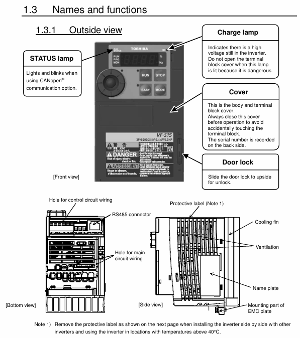
Transportation taboos: It is prohibited to handle the power circuit terminal cover by hand to prevent the cover from falling off and causing the equipment to fall off; When transporting, it is necessary to wear a cover to avoid hands from entering the wiring holes (to prevent pinch injuries).
Installation environment: The ambient temperature should be between -10 ° C and 60 ° C, avoiding high humidity, dust, corrosive gases, and oil mist environments; When multiple frequency converters are installed side by side, the spacing should be ≥ 3cm, and the top protective label should be removed when the ambient temperature exceeds 40 ° C.
Load bearing and fixing: It should be installed on a metal plate that can bear the weight of the equipment, and it is prohibited to install it on flammable materials (fire prevention); Areas with significant vibration require additional anti vibration treatment.
2. Wiring details
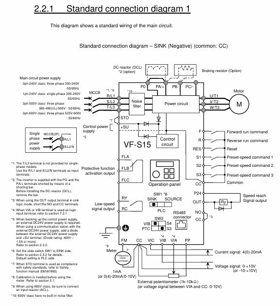
Main circuit wiring: power input terminal (3-phase is R/L1, S/L2, T/L3; The 1-phase (R/L1, S/L2/N) and motor output terminals (U/T1, V/T2, W/T3) cannot be reversed, otherwise it will damage the frequency converter and cause a fire; The braking resistor should be connected according to the manual and should not be directly connected between the DC terminals (PA/+and PC/- or PO and PC/-).
Terminal torque: The tightening torque of screws of different specifications must be strictly followed to avoid poor contact and fire hazards, as shown in the table below:
Recommended torque for screw specifications (N · m) corresponds to torque (lb · in)
M3.5 1.0 8.9
M4 1.4 12.4
M5 2.4 20.8
M6 4.5 40.0
M4 (Grounding) 1.4 12.4
M5 (Grounding) 2.8 24.8
Control circuit: The control circuit terminal block needs to be disassembled and assembled in a power-off state. The wire specification is 0.3-1.5mm ² (twisted wire), and the stripping length is 6mm. It is recommended to use a specified type of wire nose (such as the AI series of PHOENIX CONTACT).
Operation and parameter settings
1. Basic operating mode
Command mode (cmod): Used to select the control source for motor start stop, with a default value of 1 (panel operation), which can be set to 0 (terminal block), 2 (RS485 communication), 3 (CANopen communication), etc. Switching should be performed when the motor is stopped (switching is prohibited during operation when f736=1).
Frequency setting mode (fmod): used to select the input method for frequency commands. The default value is 0 (set dial 1, save frequency after power failure), and can be set to 1 (0-10V signal of terminal VIA), 4 (RS485 communication), 11 (pulse sequence input), etc.
2. Core parameter configuration
Acceleration/deceleration time: Acceleration time 1 (acc) defaults to 10.0s, deceleration time 1 (dec) defaults to 10.0s, and the unit can be changed to 0.01s through parameter f519; supports automatic acceleration and deceleration (au1=1), and the time can be automatically adjusted according to the load.
Frequency parameters: The maximum frequency (fh) defaults to 80.0Hz, the upper limit frequency (ul) defaults to be related to the setup menu, and the lower limit frequency (ll) defaults to 0.0Hz; the jump frequency (f270-f275) can be set in three groups to avoid mechanical resonance, such as f270=50Hz and f271=2Hz (jump width).
Motor protection: Electronic thermal protection level 1 (thr) defaults to 100% (based on the rated current of the frequency converter), and needs to be adjusted according to the rated current of the motor. If the rated current of the motor is 42% of the frequency converter, thr needs to be set to 42%; The overload characteristic selection (aul) can be set to 1 (constant torque 150% -60s) or 2 (variable torque 120% -60s).
Special function: Automatic restart (f301=1) can detect the motor speed and smoothly restart after an instantaneous power outage; The retry function (f303=1-10) can automatically retry after overcurrent, overvoltage, and other trips, with retry intervals increasing from 1 second to 10 seconds.
Monitoring and fault handling
1. Status monitoring
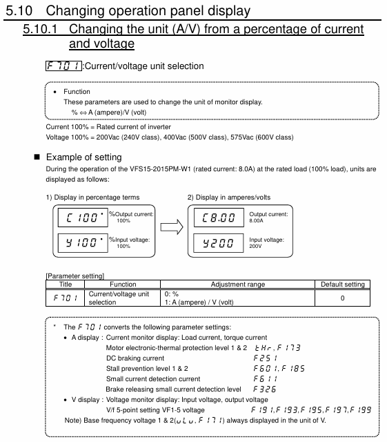
Standard monitoring mode: default display output frequency (f710=0), switchable display of output current, input voltage, etc; Supports peak hold (f709=1) and minimum hold (f709=2), triggered by EASY key (f750=3).
Status monitoring mode: It can view frequency command values, terminal input/output status, PID feedback values, etc., to help determine whether the inverter is operating normally.
2. Troubleshooting and Handling
Common causes of tripping: overcurrent (OC1-OC3, need to check motor short circuit and excessive load), overvoltage (OP1-OP3, need to check brake resistance and deceleration time), overload (OL1-OL3, need to check motor rated current and THR setting), overheating (OH, need to clean heat sink and reduce carrier frequency).
Reset requirement: After tripping, the cause of the fault must be eliminated first, and the operation command must be confirmed to be turned off (to avoid sudden motor start-up). Reset twice through the panel STOP button or terminal RES reset.
Maintenance and disposal
1. Regular inspection
Daily inspection: Check the appearance of the frequency converter daily for any damage, abnormal sounds/odors, and whether the cooling fan is operating normally.
Regular inspection: Clean the heat sink and cooling fan every 6 months; Check the tightness of the terminal screws (tighten them to the specified torque); Confirm that the grounding wire is securely connected.
2. Component replacement and lifespan management
Cooling fan: The accumulated running time can be viewed through status monitoring, and after replacement, typ=9 needs to be reset to zero; Fan failure can cause the frequency converter to overheat and trip.
Capacitor: The lifespan is calculated based on the ambient temperature (f634, default 21-30 ° C). When the accumulated operating time reaches the alarm value, it needs to be replaced in a timely manner (to avoid capacitor explosion).
3. Disposal of waste
The frequency converter needs to be disposed of by an industrial waste disposal specialist (such as "industrial waste collection and transportation personnel"), and it is prohibited to disassemble it by oneself to prevent capacitor explosion or harmful gas generation.
Compliance and Appendix
Standard compliance: The document includes compliance measures for CE certification, UL standards, and CSA standards, such as installing EMC boards and shielding wire connections; 600V level requires mandatory connection of input reactor (ACL).
Appendix information: Provide parameter default value table, terminal function table, fault code table, and differences in setup menu settings in different regions (such as EU, Asia, Japan).
- YOKOGAWA
- Reliance
- ADVANCED
- SEW
- ProSoft
- WATLOW
- Kongsberg
- FANUC
- VSD
- DCS
- PLC
- man-machine
- Covid-19
- Energy and Gender
- Energy Access
- Renewable Integration
- Energy Subsidies
- Energy and Water
- Net zero emission
- Energy Security
- Critical Minerals
- A-B
- petroleum
- Mine scale
- Sewage treatment
- cement
- architecture
- Industrial information
- New energy
- Automobile market
- electricity
- Construction site
- HIMA
- ABB
- Rockwell
- Schneider Modicon
- Siemens
- xYCOM
- Yaskawa
- Woodward
- BOSCH Rexroth
- MOOG
- General Electric
- American NI
- Rolls-Royce
- CTI
- Honeywell
- EMERSON
- MAN
- GE
- TRICONEX
- Control Wave
- ALSTOM
- AMAT
- STUDER
- KONGSBERG
- MOTOROLA
- DANAHER MOTION
- Bentley
- Galil
- EATON
- MOLEX
- Triconex
- DEIF
- B&W
- ZYGO
- Aerotech
- DANFOSS
- KOLLMORGEN
- Beijer
- Endress+Hauser
- schneider
- Foxboro
- KB
- REXROTH
- YAMAHA
- Johnson
- Westinghouse
- WAGO
- TOSHIBA
- TEKTRONIX
- BENDER
- BMCM
- SMC
- HITACHI
- HIRSCHMANN
- XP POWER
- Baldor
- Meggitt
- SHINKAWA
- Other Brands
- UniOP
- KUKA
- IBA
- Beckhoff
-
ADLINK CPCI-6860A - 51-31310-OB10 industrial motherboard CompactPCI SBC
-
ADLINK AmITX-SL-G-H110 - 51-7A104-0A30 Mini-ITX Industrial Motherboard
-
ADLINK PXI-2005-003 - CPCI Industrial PC Data Acquisition Card Multi-Function DAQ
-
ADLINK DININ-814M - 51-14032-0A3D SCSI-100P cable connection Interface Terminal Board
-
ADLINK CPCI-3920NA/C2D15/M1G - 3U CompactPCI Intel Core 2 Duo Single Board Computer
-
ADLINK PCIE-8560 - 51-18014-0A20 Communication Card High Speed DAQ
-
ADLINK PCI-C154+ - Motion Control Card 4-axis Motion Controller Board
-
ADLINK PCI-RTV24 - image capture card Analog Video Frame Grabber
-
ADLINK NuPRO-842LV/P - 51-41360-0B30 Industrial Motherboard CPU Board
-
ADLINK cBP-3208/3208R - CPCI Board 3U 8-Slot CompactPCI Backplane
-
ADLINK PCI-8164 - 4-Axis Motion Controller PCI Card 51-12406-0A40
-
ADLINK PCIe-GIE64+ - 4-CH GigE Vision PoE+ Frame Grabber Video Capture Card
-
ADLINK CPCI-6860 / 6860A - CompactPCI Dual Xeon Single Board Computer
-
ADLINK IEC-915GV - REV 1.1 Industrial motherboard CPU Board
-
ADLINK ND-6520 - Technology RS-232 to RS-422RS-485 Converter NuDAM Module
-
ADLINK RTV-24 / PCI-MP4S - 51-12519-1C30 4-Channel Real Time Video Capture Board
-
ADLINK cPCI-6910 / cPCI-6910AM/M1G - cPCI-6910AM/DXL16/M1G/S80G(G)-3120 BOARD CompactPCI SBC
-
ADLINK NUPRO-A40H - Linghua 51-41807-1A30 Industrial Control Computer Motherboard
-
ADLINK USB-3488A - USB to GPIB INTERFACE USB-3488A(G) Controller Module
-
ADLINK PCI-8134A - motion control card 4-Axis Controller Card
-
ADLINK PCI-8134 - 51-12403-0B20 PCB Board Motion Controller Card
-
ADLINK LPCI-3488A - PCI Card 51-12801-0A30 Low Profile IEEE-488 GPIB Card
-
ADLINK NUPRO-900A - industrial computer motherboard Single Board Computer
-
ADLINK cPCI-6840V - industrial control motherboard CompactPCI SBC
-
ADLINK M-342 - industrial motherboard ATX Mainboard
-
ADLINK NUPRO-935A/LV - industrial control motherboard
-
ADLINK cPCI-3538 - CompactPCI Async Serial Communications Module
-
ADLINK PCI-1610 - Card 4-Port RS-232 PCI Serial Communication Card
-
ADLINK HSL-DI32-DB-N - Distributed I/O Module 32-CH Digital Input
-
ADLINK CPCI-6860A - motherboard E7501 CompactPCI Single Board Computer
-
ADLINK PCI-8134A - 4-Axis Motion Control Card PCB Board
-
ADLINK EURESYS LINK - grabbers Video Capture Card Frame Grabber
-
ADLINK NuPRO-965DV - motherboard Industrial Control Board
-
Thermo Fisher Scientific 80100-60500 - 80000-61010R 80000-21000R 80000-60457 Spectrum System Controller ADLINK Components
-
ADLINK PCI-7296 - IO card High Density 96-CH Opto-Isolated DIO Card
-
ADLINK MXC-6322D - Matrix Industrial Computer Fanless Embedded PC
-
ADLINK DIN-825-GP4 - connector board Terminal Block Interface
-
ADLINK AMP-208C - Motion Control Card DSP-based 8-axis
-
ADLINK PCIe-GIE72 - 51-18531-0A10 2-CH GigE Vision Frame Grabber PoE+ Card
-
ADLINK PXIS-3320 - PXI/PXIe Chassis 15-slot 6U PXI/CompactPCI SEM-I-1518=9N41
-
ADLINK MI-965 - Industrial CPU Motherboard
-
ADLINK M-302 - Industrial control motherboard
-
ADLINK PCI-6308V - 51-12202-0A50 Isolated Analog Output Card PCB-I-E-1813=ZA03
-
ADLINK NUPRO-935A - Industrial Mother Board CPU Board
-
ADLINK PCI-7434 - PLOTECH Digital Output Card PCB-I-E-1182=6EX2
-
ADLINK PCI-7432 - 64 Channel Isolated Digital I/O PCI CARD
-
ADLINK NUPRO-935A/DV - 51-41802-0A10 motherboard Industrial Control Board
-
ADLINK PCIe-GIE72 - 51-18531-0A10 2-CH GigE Vision Frame Grabber PoE+ Card
-
ADLINK HSL-DI16DO16-M-NN - HSL-DI16DO16-M-NN(G)-0280 Discrete I/O Module Distributed I/O
-
ADLINK cPCI-6760D / cPCI-6840V - cPCI Single Board Computer Industrial Motherboard
-
ADLINK NuPRO-A301 - Motherboard IPC Motherboard
-
ADLINK NuPRO-935A/LV - motherboard Industrial Control Board
-
ADLINK NUPRO-E320LV - motherboard Industrial Control Board
-
ADLINK NuPRO-E42 - Industrial Control Board Motherboard
-
ADLINK M-342 - ATX Motherboard Industrial PC Mainboard
-
ADLINK CPCI-6860 / 6860A - Industrial Control Motherboard CompactPCI SBC
-
ADLINK AmITX-SL-G-Q170/GEHC(EA)-021E - 51-7A104-0A20 Industrial Motherboard w/ DDR4
-
ADLINK NUPRO-852 / NUPRO-852LV - industrial control motherboard
-
ADLINK DAQ-2006-004 - Multi-Function DAQ Cards Data Acquisition
-
ADLINK PCIe-RTV24 - Frame Grabbers Video Capture Cards PCI-e x1 4-CH 120fps
-
ADLINK PCI-8134 - 51-12403-0B20 4-Axis Motion Controller Card
-
ADLINK PCI-8132 - 2-Axis Motion Controller Card
-
ADLINK cBP-6402 - Backplane Passive Backplane
-
ADLINK cPCI-6760D - cPCI Single Board Computer Industrial Control Motherboard
-
ADLINK DIN-825-4PO(G)-0030 - Terminal Board Motion Control Breakout Board
-
ADLINK M-322 - Industrial Motherboard
-
ADLINK ABX-1301 - 51-63808-0A20 Industrial Motherboard
-
ADLINK PCI-7433 - 64-CH Isolated Digital Input Card
-
ADLINK AMP-208C - Motion Control card
-
ADLINK DIN-50S-01 - TECHNOLOGY TERMINAL BLOCK INTERFACE MODULES W/ DIN RAIL
-
ADLINK PCI-8134 - 51-12403-0B20 4-Axis Motion Controller Card
-
ADLINK MXE-201/MSSD64G - Technology Automation Computer Fanless Embedded System
-
ADLINK USB-3488A (G) - USB to GPIB CARD Controller Interface
-
ADLINK cPCI-3720L2 - SBC Single Board Computer PCB AMAT 0190-14599
-
ADLINK PCI-7251 - Relay Output Board Expansion Module
-
ADLINK PCI-8124-C - PCB Board 4-CH Encoder Trigger Card
-
ADLINK HD636 - Industrial Computer Board PCB-I-E-2200=9L32-2 Main Board
-
ADLINK USB-3488A - THERMOTRON INDUSTRIES IEEE 488 CPU INTERFACE WITH USB/GPIB
-
ADLINK MI-965 - motherboard Industrial CPU Board
-
ADLINK LPCIe-7250 - Technology Digital IO card Low Profile PCIe Relay Output
-
ADLINK NuPro-720/SCOPUS - Technology With 256MB Industrial MotherBoard
-
ADLINK NuPR0-840 - industrial control motherboard
-
ADLINK M-342 - Motherboard ATX PC Mainboard
-
ADLINK MI-965 - motherboard Industrial CPU Board
-
ADLINK CPCI-6530V/4402E/M4G - AMAT CPCI-6503VED/4402E/M4-0/SD64G-2550 Universal SBC
-
ADLINK IMB-M43-IRV - Industrial Motherboard ATX PC Board
-
ADLINK 52983 / 58183 - Chroma PXI I/O Input/Output Card + Carrier Adapter
-
ADLINK PXI-3920 - PXI 3U cPCI Industrial Controller w/ RAM SSD Embedded CPU
-
ADLINK NuPRO-842LV/P - motherboard Industrial Control PC Board
-
ADLINK PCI-7442 - 64-Channel Datalogging Acquisition Switch Card
-
ADLINK PCIe-RTV24 - Cadre Agrippeurs Vidéo de Capture Cartes Pci-E x1 4-CH
-
ADLINK ACL-7122A - TECHNOLOGY 51-11004-1A1 CIRCUIT BOARD 96-CH DIO Card
-
ADLINK PCIe-RTV24 - 51-18016-0A20 Image Acquisition Video Capture Card
-
ADLINK AMP-204C - DSP-Based 4-Axis Advanced Pulse-Train Motion Controller
-
ADLINK 52981 / 58183 - Chroma PXI Digital I/O DIO Input/Output Card + Carrier Adapter
-
ADLINK PCI-8102 - motion control card 2-Axis
-
ADLINK NuPRO-E320LV - industrial computer motherboard
-
ADLINK PCI-RTV24 - card Analog Video Capture Frame Grabber
-
ADLINK M-302 - Motherboard P/N: 08GSAQ96501102
-
ADLINK NEON-1020 - Smart camera Industrial Machine Vision
-
ADLINK AMP- 208C - card DSP-based 8-axis Motion Controller
-
ADLINK PCI-9114DG - Multi-Function Daq Card Data Acquisition
-
ADLINK MXC-6322D/BE_FanG) - Matrix PM2-MXC Fanless Embedded Computer
-
ADLINK DIN-825-4P0 - Terminal Board Motion Control Breakout Board
-
ADLINK HPCI-8S4 REV.B2 - Industrial Control Base Plate Passive Backplane
-
ADLINK HSL-DI32-DB-N - Distributed I/O Module 32-CH Digital Input
-
ADLINK NuPRO-935A/DV - industrial control motherboard
-
ADLINK PCI-7442 - Switch card 64-CH Datalogging Acquisition Card
-
ADLINK NuPRO-E42 - motherboard 51-41808-0A30 Industrial Motherboard
-
ADLINK CPCI-3610D/N45/M1G(G)-10B0 - CompactPCI Intel Atom Single Board Computer CPU Board
-
ADLINK LPCI-7250 - GP Output Isolated Digital Input Card PCB 51-12803-0A10
-
ADLINK PCI-7250 - 51-12007-0A40 PCI7250 8-CH Relay Output & 8-CH Isolated DI Card
-
ADLINK STC-1005 - 10.4inch touch panel PC E3845 CPU
-
ADLINK PCI-FIW64 - image card FireWire Frame Grabber
-
ADLINK NuPRO-935A/LV - industrial computer motherboard
-
ADLINK PCI-8164 00B0 - Centralized Motion Controller 4-axis PCB-I-E-1179=6EX2
-
ADLINK ACLD-9137F REV A1 - 51-14006-101 Screw Termination Board
-
ADLINK PCI-7248 - 51-12006-0A40 Control Card Digital I/O
-
ADLINK HPCI-8S4 - Technology Backplane PCB GaSonics 3500 Asher Passive Backplane
-
ADLINK NuPRO-E320LV - Cpu Board 51-41804-0A20 Industrial Motherboard
-
ADLINK HPX-13S4 - device baseboard Passive Backplane
-
ADLINK M-322 - industrial motherboard
-
ADLINK NuPRO-865 REV :3.0 - industrial motherboard
-
ADLINK DIN-68S-01 - Terminal Block Interface Module Cable Connection
-
ADLINK ETX-IM266-C100Z - motherboard ETX CPU Module
-
ADLINK NuPRO-E320LV - motherboard Industrial Control Board
-
ADLINK NuPRO-841 REV:2.0 - motherboard Industrial PC Board
-
ADLINK ETX-AT-N270-18 - N270 Board ASH-EAT-18/S512 ET Mainboard

K-JIANG

Add: Jimei North Road, Jimei District, Xiamen, Fujian, China
Tell:+86-15305925923