
K-WANG


EATON XV200 Mini Panel Operation Instructions
EATON XV200 Mini Panel Operation Instructions
Basic information and product specifications
Core positioning and applicable scenarios
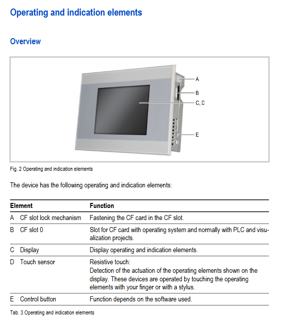
Equipment type: Can be used as an independent HMI device or integrated HMI/PLC device;
Applicable fields: Designed specifically for mechanical and system manufacturing, used for equipment visualization, operation, and control. Other uses require confirmation from the manufacturer;
Product alias: XV200 and MK2 are different names of the same product, with completely identical model parameters.
The equipment is divided into 6 categories based on "display type+interface combination" according to the model version classification, and the core differences are shown in the following table:
Model (XV200 series) Model (MK2 series) Display type Core interface (non electrically isolated)
XV-232-57BAS MK2-232-57BAS monochrome RS232
XV-230-57MPN MK2-230-57MPN monochrome Profibus
XV-230-57CNN MK2-230-57CNN monochrome CAN
XV-252-57MPN MK2-252-57MPN Color RS232+Profibus
XV-252-57CNN MK2-252-57CNN Color RS232+CAN
Key technical parameters
Display system: 5.7-inch QVGA (320 × 240 pixels), visible area of 115 × 86mm; monochrome screen supports 256 grayscale, color screen supports 256 colors; Backlight is 1 × CCFL, with a lifespan of 50000 hours, and software adjustable brightness (100%/80%);
Touch sensor: 4-wire resistive, made of glass and polyester film material, calibrated at the factory;
System configuration: 32-bit RISC processor (200MHz), 32MB DRAM, 1.5MB available FLASH, 100 bytes available NVRAM; Support Type I CF cards (for storing operating systems, programs, and data); Built in CR2032 lithium battery (190mA/h), clock backup life of 10 years after power failure;
Power supply requirements: 24 VDC SELV (safe extra low voltage), allowable voltage range 18.0-31.2 VDC (including ripple), short-term (<100ms) can withstand 35 VDC; Maximum power consumption of 8W, continuous current of 0.35A, starting surge current of 2.0A/2s; Equipped with reverse protection and maintenance free fuses, with no potential isolation;
Protection and physical dimensions: front panel protection level IP65, back panel IP20; Dimensions: 212 (width) × 156 (height) × 55 (depth) mm, installation incision: 198 × 142mm (± 1mm), weight: approximately 0.7kg.
Safety regulations and taboos
Personnel and operational requirements
Qualification requirements: Installation, operation, and maintenance personnel must undergo professional training, be familiar with manuals and relevant safety regulations;
Manual usage: The complete manual must be used, and single page operations are prohibited (to avoid missing safety information);
Prohibited from use: Safety functions that cannot be used for personnel or equipment protection, can only be used for routine control and visualization.
Core safety hazards and preventive measures
Potential hazards prevention measures
Explosion risk (explosive environment) is only applicable to non explosive environments or ATEX Zone 22 areas; Avoid severe impact on equipment; Power off before plugging or unplugging the plug
Electric shock risk (opening cover): Do not open the cover by yourself, as it contains live parts inside
Static electricity damage (electronic components): Before touching the device, ground it to release static electricity; Avoid contact with sensitive components such as interface pins
Data loss (CF card): Only power off and unplug the CF card; Enable card slot locking mechanism; Avoid frequent write operations (limited CF card write cycle)
Condensation short circuit (temperature fluctuation) equipment must not be powered on during condensation; After the temperature changes, it needs to be allowed to stand at room temperature before starting
Touch screen damage (sharp objects) can only be operated with fingers or a dedicated stylus; Wear gloves that are clean and free of sharp particles
Environmental restrictions
Avoid direct sunlight exposure (UV can cause plastic to become brittle and shorten its lifespan);
Prohibit the use of corrosive/abrasive cleaning agents to prevent liquids from entering the equipment.
Installation process and specifications
Installation prerequisites
Environmental requirements: operating temperature 0-50 ℃, storage/transportation temperature -20-60 ℃; Humidity of 10-95% without condensation;
Installation location: inside the control cabinet/control panel, can be installed horizontally/vertically; Ventilation gap ≥ 3cm, away from heat sources (such as transformers) ≥ 15cm;
Installation surface requirements: thickness 2-5mm, flatness ≤ 0.5mm, surface roughness Rz ≤ 120.
Cable and wiring specifications
Cable requirements: All bus interfaces require shielded cables, with the shielding layer connected to the connector housing with low impedance to ensure EMC compliance;
Special interface requirements:
CAN interface: Cable characteristic impedance of 120 Ω, maximum length of 5000m (at 10 Kbit/s), and 120 Ω terminal resistors need to be connected at both ends of the bus;
Profibus interface: Cable characteristic impedance of 150 Ω, maximum length of 1200m (≤ 93.75 Kbit/s), terminal resistors need to be connected at both ends of the bus;
Ethernet interface: shielded twisted pair (STP) is used, cross line is used between equipment, and straight line is used to connect to the switch, with a maximum length of 100m; the Internet needs to be isolated or protected by firewall;
Common requirement: The GND terminals of all bus stations must be interconnected to avoid potential damage to equipment.
Equipment fixation and sealing
Installation steps: Prepare a 198 × 142mm (± 1mm) incision → Install a sealing strip in the groove (with the joint facing downwards, without distortion) → Insert the device from the front → Secure with 8 brackets with threaded pins;
Torque requirement: The maximum tightening torque for the bracket threaded pin is 0.1 Nm to avoid over tightening and damaging the equipment;
IP65 requirement: 8 brackets must be fully installed (2 on the left/right/top/bottom), and the installation of 4 brackets does not meet IP65 protection.
Operation and maintenance
Startup and shutdown
Startup process: Power off and insert the CF card containing the operating system → Lock the card slot → Power on and boot → Complete system settings (such as time and brightness) according to the manual → Install application programs;
Closing process: Confirm no CF card write operation → Power off; Avoid frequent switching (which can shorten backlight life at low temperatures), and prioritize reducing brightness instead of shutting down.
routine maintenance
Touch screen cleaning: Wipe with a clean, soft, and damp cloth. For stubborn stains, spray a small amount of cleaning agent on the cloth (do not directly spray the device);
Touch screen calibration: It has been calibrated at the factory. If there is an abnormal response, it needs to be recalibrated according to the "MN05010007Z-EN" manual;
Battery maintenance: The built-in CR2032 lithium battery is non replaceable and has a lifespan of approximately 10 years;
Maintenance restrictions: Equipment malfunctions can only be reported to the manufacturer or authorized center, and self opening repairs are prohibited.
Common troubleshooting
Possible causes and solutions for the fault phenomenon
The device cannot start and the power is not connected/CF card is not inserted/CF card has no operating system. Check the power cable → Insert CF card with OS → Replace the faulty CF card
Touch screen unresponsive uncalibrated/obstructed by objects/installed too tightly recalibrated → remove obstruction → loosen bracket threaded pin
Display black screen backlight off/backlight fault check visualization software backlight settings → Contact maintenance
When starting, prompt 'No CF card'. The CF card is not inserted or has poor contact. Power off and reinsert the CF card and lock it
Storage, transportation, and disposal
Storage and transportation
Storage conditions: Meet the requirements of temperature -20~60 ℃, humidity 10-95% without condensation, avoid heavy pressure and severe vibration;
Transportation requirements: Use original factory packaging and inspect the equipment for any transportation damage upon arrival.
Disposal standards
The equipment contains lithium batteries (CR2032) and mercury containing cold cathode tubes (<5mg), which must be disposed of in accordance with relevant national regulations and cannot be discarded at will;
The shell material is halogen-free ABS-PC, and the packaging is made of cardboard and PE film, which can be classified and recycled.
Compliance and Standards
The equipment complies with multiple international standards, including:
Safety standards: UL 60950, IEC/EN 60950;
EMC standards: 2004/108/EC, IEC/EN 61000 series;
Explosion proof standard: ATEX 94/9/EC (Zone 22, Category 3D);
Product standards: EN 50178, IEC/EN 61131-2.

- YOKOGAWA
- Reliance
- ADVANCED
- SEW
- ProSoft
- WATLOW
- Kongsberg
- FANUC
- VSD
- DCS
- PLC
- man-machine
- Covid-19
- Energy and Gender
- Energy Access
- Renewable Integration
- Energy Subsidies
- Energy and Water
- Net zero emission
- Energy Security
- Critical Minerals
- A-B
- petroleum
- Mine scale
- Sewage treatment
- cement
- architecture
- Industrial information
- New energy
- Automobile market
- electricity
- Construction site
- HIMA
- ABB
- Rockwell
- Schneider Modicon
- Siemens
- xYCOM
- Yaskawa
- Woodward
- BOSCH Rexroth
- MOOG
- General Electric
- American NI
- Rolls-Royce
- CTI
- Honeywell
- EMERSON
- MAN
- GE
- TRICONEX
- Control Wave
- ALSTOM
- AMAT
- STUDER
- KONGSBERG
- MOTOROLA
- DANAHER MOTION
- Bentley
- Galil
- EATON
- MOLEX
- Triconex
- DEIF
- B&W
- ZYGO
- Aerotech
- DANFOSS
- KOLLMORGEN
- Beijer
- Endress+Hauser
- schneider
- Foxboro
- KB
- REXROTH
- YAMAHA
- Johnson
- Westinghouse
- WAGO
- TOSHIBA
- TEKTRONIX
- BENDER
- BMCM
- SMC
- HITACHI
- HIRSCHMANN
- XP POWER
- Baldor
- Meggitt
- SHINKAWA
- Other Brands
- UniOP
- KUKA
- IBA
- Beckhoff
-
LTI SC52.0040.0012.0000.0 - Servo Drive
-
Lti SC52.0040.0012.0000.0 - Servo Drive
-
Milton Industries LTI Tool By Milton LT1240 - 1/2" Drive Lugnut Remover
-
LTi Drives SO84.200.P030.0000.0-W - Servo Spindle Drive
-
LTI DRIVES LSP08-035-320-30-B0R1PY170 - Servo Motor
-
LTI DRIVES SE84.200.SC00.0001.0-W - Servo Drive
-
Lust CDE34.005.W2.2 - Lti Drives Controller
-
LTi SO84.012.0030.0011.2 - ServoOne Servo Drive
-
LTi Drives SO CM-P.0010.11.00.0 - Servo Drive Controller
-
LTi CDE34.017.W3.0 - Servo Drive
-
LTI Drives CDB32.004, C2.0,SH - Positioning Controller
-
LUST CM-CAN1 - LTi DRIVES Communication Module
-
LTi SO84.012.1030.0000.2 - Servo Drive
-
LTI MOOG CDE54.044 - PITCHMASTER FREQUENCY CONVERTER 181-01019
-
MOOG LTI 181-01019 CDE54.044 - PITCHMASTER FREQUENCY CONVERTER
-
Lust LTi Drives CDE34.010,D2.0 - Servo Drive Controller
-
LTI SO84.032.0003.0101.2 - Servo Drive
-
Seagate 9CC132-302 Harris LTI-CS IRT-34-0021-01 - Hard Drive 160GB
-
LTI SO84.032.0003.0001.2 - Servo Drive
-
LTI SO24.007.0070.0000.1 - SERVO CONTROLLER
-
LTi drive CDA32.003.C3.0.H05-01.PC1 - Servo Drive
-
LTI SO84.016.0030.0000.2 - SERVO CONTROLLER
-
LUST LTI CD A34.008,W1.4, BR - SERVO DRIVE
-
MOOG LTI 181-01019 CDE54.044 - PITCHMASTER FREQUENCY CONVERTER
-
LTI MOOG 181-01019 - PITCH Master Servo Drive CDE54.044
-
LTI SERVO ONE SO84.045.0030.0001.2-W - Drive
-
LUST LTi SO84.032.0040.0000.2 - SERVO ONE DRIVE
-
LTi Drives LSH-074-2-30-3 20/T1,G6.1M - SERVO MOTOR
-
LTI SO84.016.0000.0101.2 - servo drive
-
LTI SA54.0550.0033.0000.0 - Servo Drive
-
LTI SA54.0550.0033.0000.0 - Servo Drive
-
LTI LT 4850 - 3/8" Drive 3-Pc Twist Socket Transmission Drain Plug Removal System
-
LTI Tools LT4400-30 Lock Technology - 3/4" Twist Socket 1/2" Drive Lugnut Remover
-
LTI Tools LT-1400C - 1/2 Drive Wheel Torque Extension Tool
-
LTI Tools LT1250 - 1/2" Drive Dual Sided Socket Lug Nut Remover Tool
-
LTI SO84.032.0003.0101.2 - Servo Drive
-
LTI MOOG 181-01019 - PITCH Master Servo Drive CDE54.044
-
MOOG LTI 181-01019 CDE54.044 - PITCHMASTER FREQUENCY CONVERTER
-
MOOG LTI 181-01019 CDE54.044 - PITCHMASTER FREQUENCY CONVERTER
-
MOOG LTI 181-01019 CDE54.044 - PITCHMASTER FREQUENCY CONVERTER
-
LTI SA54.0550.0033.0000.0 - Servo Drive
-
LTI Tools LT-4800 - 7 Piece Twist Socket 3/8" Drive Oil Drain Plug Removal Set
-
LTI SA54.0550.0033.0000.0 - Servo Drive
-
LTI Drive SO24.007.00300000.0 - Servo Drive
-
LTI TOOLS LTI 1400-I - Drive Wheel Torque Extension
-
LTI Tools LT4400-3 - 3/4" 19mm Twist Socket 1/2" Drive Lugnut
-
LTI TOOLS LTI 1400-BB - Drive Wheel Torque Extension
-
LTI SO84.032.0003.0101.2 - Servo Drive
-
LTI Tools LT-4512 - 3/8" Drive 12mm Twist Socket
-
LTI MOTION Luster SO84.032.0003.0001.2 - Servo Drive
-
LTI Tool By Milton LT1600P - 1" Drive Torx Stick
-
LTI Lust VF1424L,HF,OP2,S56 - Variable Frequency Drive
-
LUST CDA32.004,C1.4,H08,B0 - SERVO DFRIVE CM-CAN1 Module
-
LTI SO84.045.0002.0001.2-W - Drive
-
LTI Lust VF1404M,C9,PT1,BR1 - Inverter Type VF1404M
-
LTI SA54.0550.0033.0000.0 - Servo Drive
-
LTI Tools LT-1400C - 1/2" Drive Wheel Torque Extension
-
Lust LTI DRiVES CDA32.006, C3.0, H09 - Variateur De Fr茅quence Frequency Inverter
-
LTI MOOG CDE54.044 - PITCH master SERVO DRIVE
-
LTI MOOG CDE54.044 - PITCH master SERVO DRIVE
-
LTI SO84.143.0020.0101.2-W - servo drive
-
LTI MOTION SC34.0200.0011.0000.0 - Servo drives
-
LTI SO84.032.0003.0001.2 - Servo Drive
-
LTI DRIVES GmbH MS100 - Assembly Set Mounting Kit
-
LTI SO84.032.0003.0001.2 - Servo Drive
-
LTI SO84.032.0003.0001.2 - Servo Drive
-
LTI MOTION SO84.032.0003.0101.2 - servo drive
-
LTI SO84.032.0003.0101.2 - Servo Drive
-
LTI MOOG CDE54.044 - PITCH master SERVO DRIVE
-
LTI MOTION CDE32.004.C2.4 - Servo drives
-
LTI CDD34.032锛學x.x锛孊R锛孭C1 - Servo Drive
-
Lust LTI DRiVES CDA32.006, C3.0, H09 - Inversor De Frecuencia Frequency Inverter
-
Lust SO84.008.0030.1000.0 - Servo One LTi Drive
-
LTI MOTION SO84.032.0003.0101.2 - Servo drives
-
LUST LTi CDA32.004,C1.4 - SERVO DRIVE
-
LTI MOOG CDE54.044 - PITCH Master SERVO DRIVE
-
LTI KEBA CDB32.004 C2.7, SH - PN: 08673530 Frequency Inverter
-
LTI Tools LT-1400C - 1/2" Drive Wheel Torque Extension
-
LTI LT1400-E - 1/2" Drive Wheel Torque Extension
-
LTI MOOG 181-01019 - PITCH master SERVO DRIVE CDE54.044
-
LTI LSN-097-0510-30-560/T1 - Actuator Motor
-
LTI Tools LT 4800 - 7 Piece 3/8" Drive Twist Socket Oil Drain Plug Removal System
-
LTI DRIVES GmbH MS100 - MONTAGESET Assembly Set Mounting Kit
-
Lti SC52.0040.0012.0000.0 - Servo Drive
-
LTI DRIVES GmbH MS100 - Juego De Montaje Assembly Set Mounting Kit
-
LTi DSM4-14.2-21R83-200 - Drives servomoteur Servo Motor
-
MOOG CDE 54.044.GDA - Pitch Master Industrielle Turbine Lti Drive
-
LTI SO24.004.0030.1000.0 - Servo Drive Controller
-
Lti MOOG CDE54.044 - Pitch Master Servo Drive
-
Lust LTI DRiVES CDA32.006, C3.0, H09 - Inverter
-
LTI MOTION GMBH CDB34.006,W3.0,PC1,H39 - Frequency inverter
-
LTI SO84.032.0003.0001.2 - Servo Drive
-
MOOG CDE 54.044.D - Pitch Master Industrielle Turbine Lti Drive
-
LTI TOOLS LT-1460 - 1/2" DRIVE WHEEL TORQUE EXTENSION KIT 5 PIECE SET
-
Lust Cdb32.003, C2.4 - Lti Drives Servoregulador Frecuencia Servo Controller Inverter
-
Lust LTI DRIVES CDA32.006, C3.0, H09 - Frequency Inverter
-
Lust Lti SO82.004.0030.0000.2 - Servo Drive
-
LTI MOTION SC34.0200.0011.0000.0-SL - Servo drives
-
LTI MOTION SA54.0075.0033.0000.0 - Servo drives
-
LTI MOTION SC32.0075.1011.0000.0 - Servo drives
-
LTI Servo-One Junior SO22.006.0080.1000.0 - Servo Controller Servoregler
-
LUST CDA32.004, C1.4, H08, B0 - Servo Drive & LTI CM-CAN1 Module
-
LTI DRIVES LSP08-035-320-30-B0R1PY170 - Servo Motor
-
LUST LTI CDA32.004,C1.4.H08.B0 - SERVO CONTROLLER DRIVES
-
LUST LTi DRiVES CDS44.072LC1.2 - Servo Drive
-
Lti Servo-One Junior SO22.006.0082.1000.0 - Servo Controller Servoregler
-
LUST CDA32.008,C2.0,HF - Lti DRIVES Spindle Drive Inverter
-
LTI SO22.003.0082.0000.0 - Servo Drives One junior Servo Controller Servoregler
-
Lust Lti Drives CM-CAN1 - Communication Module
-
LUST Lti Drives Vf1202s, G8, I6 - Frequency Inverter Drive
-
LTI DRIVES BR-090.03.540.UR.H38 - Bremswiderstand Brake Resistor
-
LTi DRIVES PM-E40.2DRA054P - Wind Turbine Pitch Control Inverter
-
LTi Drives GmbH br-110.01.540-UR - Brake Resistor
-
LTI Drives LSN-097-0960-30-0560/T1,S4,B - Servo Motor
-
LUST CDA34.006.C2.0 - LTI Drives Servoregler
-
LUST LTI DRIVES SERVO ONE JUNIOR SO24.002.0020.0000.1 - Servo Drive Controller
-
LTI MOTION SO84.032.0003.0001.2 - Servo drives
-
LTI DDTD750V2-120 - IBOP ACTUATOR CYLINDER FOR TOP DRIVE
-
LTI CDE32.004, C2.4 - SERVO DRIVE
-
LUST LTI DRIVES CDD34.017 W3.4PC1 - Servo Drive Controller
-
LTI CDA3208,C3,0,HF - AC SERVO DRIVE
-
LUST LTI DRIVES LSH-074-3-30-560/T1,G6.1S - SERVO MOTOR
-
LUST Lti CDB32.004.C2.4.SH - AC Servo Drive
-
LTi CDA32.006, C3.0, H09 - Servo Drive
-
LTI SO22.003.0010.0000.0 - Servo Drive Servo one junior Servoregler Controller
-
LTi Drives DSM4-14.2-21R83-200 - Servo Motor
-
LUST Lti Drives Lsh-097-1-30-560/T1, 1R - Servomotor
-
LTI 1237 - 7 Piece 1/2" Drive Flip Socket Set

K-JIANG

Add: Jimei North Road, Jimei District, Xiamen, Fujian, China
Tell:+86-15305925923