
K-WANG


EATON S801+series soft starter
EATON S801+series soft starter
Basic Information and Core Product Specifications
Product positioning and applicable scenarios
Equipment type: Panel/shell mounted three-phase induction motor soft starter, which controls the motor terminal voltage by adjusting the SCR conduction time to achieve smooth starting (mechanical+electrical), and closes the internal contactor bypass SCR after starting to improve efficiency;
Applicable fields: Designed specifically for industrial equipment such as chillers, pumps, and machine tools, suitable for scenarios where the starting torque is lower than the rated torque of the motor;
Core advantage: It has multiple motor protection functions, supports two starting modes, and adapts to a wide range of motor power requirements.
Core hardware and model division
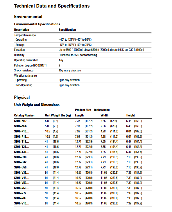
Framework and rated parameters: Divided into five major frameworks: N/R/T/U/V, the core parameters are shown in the following table:
Rated current range of frame (A) Weight (kg) Applicable motor power (kW/50Hz 400V) Number of bolts Fixed torque (Lb in/Nm)
N 11-66 2.6 10-37 4 15/1.7
R 32-135 4.8 30-80 4 25/2.8
T 56-304 18.6 51-185 6 30/3.4
U 112-500 18.6 110-300 6 30/3.4
V 112-1000 41.4 110-525 8 50/5.6
Core configuration: Built in Control Interface Module (CIM), supporting parameter configuration and fault diagnosis; Six sets of SCR full wave power bridges, equipped with electronic thermal overload protection, phase sequence detection and other functions;
Control power supply: 24 Vdc SELV/PELV, allowable voltage range 18-30 Vdc, peak withstand 35 Vdc (<100ms); Control power consumption of 25W (steady state) and 240W (impulse, 150ms).
Environmental and compliance parameters
Environmental adaptability: operating temperature -40 ℃~50 ℃, storage temperature -50 ℃~70 ℃, humidity 0-95%, no condensation; Altitude ≤ 2000m (with a capacity reduction of 0.5% for every 100m above sea level);
Compliance standards: Complies with UL 508, CSA 22.2-14-1995, IEC 60947-4-2, CCC GB14048, and has CE certification;
EMC compatibility: Anti static discharge (4kV contact/8kV air), anti electromagnetic radiation (10V/m 80-1000MHz).
Safety regulations and core taboos
Personnel and operational requirements
Qualification requirements: Installation, operation, and maintenance personnel must be professional technical personnel familiar with high-voltage safety operation standards;
Core taboos:
It is prohibited to perform live maintenance on equipment (including wiring and parameter adjustment). All power sources must be disconnected and tested first;
It is prohibited to install isolation switches on the output side (unless a shutdown linkage mechanism is configured), otherwise it may cause equipment failure or personnel danger;
The control terminal is only allowed to connect to a 24 Vdc power supply and is prohibited from connecting to 120 Vac (which will permanently damage the circuit board);
Prohibit failure to take safety measures in Auto Reset mode (which may result in accidental restart after fault clearance).
Core security risks and preventive measures
Potential risk prevention measures
During high-voltage electric shock operation, stand on an insulation pad and operate with one hand; The equipment is well grounded, and the cross-sectional area of the grounding wire is ≥ 1.5mm ²
SCR overheating ensures good ventilation and avoids frequent start-up (following start-up interval requirements); Ensure that the contactor bypasses normally after startup
Verify and save data loss parameters after configuration; Avoid power failure during parameter writing
Motor damage, correct configuration of FLA and protection parameters (such as overload trip level), prohibit disabling critical protection functions
Avoid severe vibrations during mechanical shock transportation and installation, and suitable lifting equipment is required for heavy frames (such as V-frames)
Installation process and specifications
Installation prerequisites
Installation location: inside the control cabinet/panel, can be installed horizontally or vertically; The SD card slot cannot face downwards (to prevent the card from falling off);
Spacing requirements: ventilation gap ≥ 30mm, distance from heat sources (such as transformers) ≥ 15cm;
Installation surface requirements: Panel thickness 2-5mm (N/R frame) or 1.5/2mm (V frame), flatness ≤ 0.5mm.
Cable and wiring specifications
Power cable:
Frame wire specification (Cu 75 ℃) Wiring torque (Lb in/Nm) Terminal type
N 10-2 AWG 35-50/4.0-5.6 Box Terminal
R 14-3/0 AWG 90-100/10.1-11.3 Box Terminal
T/U 4/0-500 MCM 225-250/25.5-28.3 requires EML series terminal kit
V 4/0-500 MCM 225-250/25.5-28.3 requires EML series terminal kit
Control cable: 22-12 AWG (0.33-4.0mm ²), wiring torque 3.5 Lb in (0.4 Nm); The 24 Vdc power cord should be ≥ 14 AWG (2.5mm ²) to avoid voltage drop;
Grounding specification: The equipment needs to be grounded for protection. The cross-sectional area of the grounding wire should be ≥ 1.5mm ², the length should be ≤ 350mm, and the tightening torque should be 1.3 Nm;
Phase requirement: The default incoming phase sequence is ABC. If the motor rotates in the wrong direction, the motor end or soft starter output end can be switched between two phases (switching input ends is prohibited as it may trigger phase sequence faults).
Equipment fixation and sealing
Fixing method: Fix with 4-8 bolts according to the frame (4 N/R frames, 6 T/U frames, 8 V frames), with bolt grade ≥ 5.8;
Sealing requirements: Ensure that the terminal cover plate and sealing strip are intact during installation, and install a ventilation fan (500 ft ³/min) on the V-frame as required.
Operation and Configuration
Startup and control mode
Startup mode:
Voltage ramp start (default): gradually increase the voltage from the initial torque (0% -85%), start for 0.5-180 seconds, and bypass SCR after the motor reaches synchronous speed;
Current limited startup: Constant voltage control, limiting startup current, suitable for scenarios with limited grid capacity (not recommended for variable torque loads such as fans/pumps);
Kick Start auxiliary function: outputting 0-2s torque pulses (0% -85%) during startup, used to overcome static friction or high inertia loads;
Control method:
Local terminal control: Start stop and fault reset are achieved through terminals P (allow), 1 (start), 2 (Jog), and 4 (reset);
CIM configuration: Set FLA, boot mode, protection parameters, and view fault codes through CIM.
Core parameter configuration
Required parameters:
Parameter Name Configuration Range Default Value Description
Motor FLA 32% -100% frame rating frame minimum value needs to match motor nameplate FLA to ensure overload protection is effective
Overload trip level 5-30s 20s corresponding to motor overload withstand time
Start time: 0.5-180s, 20s. The time for the voltage ramp to reach the rated voltage
Initial torque 0% -85% 45%. The proportion of starting initial torque to locked rotor torque
Reset mode manual/automatic manual/automatic mode may cause a restart after the fault is cleared
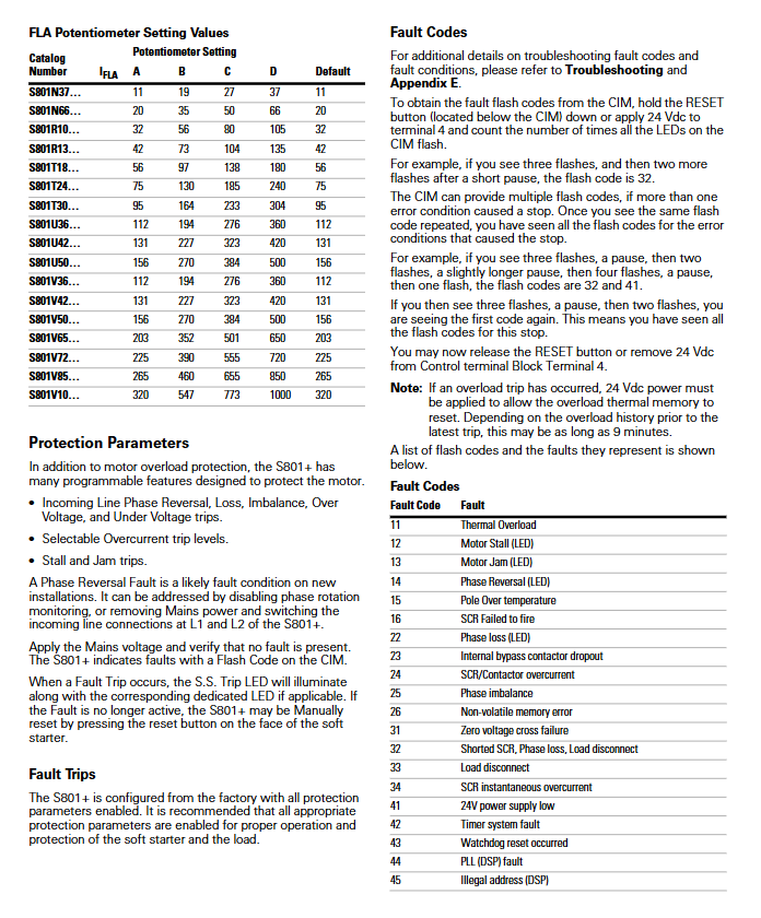
Protection parameters (enabled by default, can be disabled): overload, phase loss, phase sequence error, locked rotor, SCR overheating, overcurrent, phase imbalance.
Fault diagnosis and handling
Fault code reading: Long press the CIM reset button or apply 24 Vdc to terminal 4, and identify the fault code by the number of LED flashes (e.g. 3 flashes+2 flashes=fault code 32);
Common fault codes and solutions:
Fault code, fault type, solution
Reduce motor load due to thermal overload, check FLA configuration, wait for cooling (3-9 minutes)
22. Check the incoming power supply, fuses, and wiring tightness for phase loss
14 phase sequence error exchange motor end or soft starter output end two-phase
32 SCR short circuit/phase loss power-off measurement SCR resistance (normal ≈ 10k Ω, short circuit<5 Ω), contact maintenance
12 motor stalling, clearing load obstacles, increasing starting time or initial torque
Maintenance and Accessories
routine maintenance
Regular inspection: wiring tightness, ventilation hole cleanliness, contactor status (no abnormal noise);
Periodic verification: validity of protection parameters, rationality of startup curve, and zeroing of fault records;
Attention: After an overload fault, wait for the cooling time (3 minutes for one fault, 6 minutes for two faults, and 9 minutes for three faults). The cooling timer cannot be reset when the power is turned off.
Accessory selection
Terminal kit: EML22-26 for T/U frame, EML28-33 for V frame;
Installation accessories: installation board (EMM13 series), vibration board (EMM14 series), IP20 protection kit (SS-IP20 series);
Replacement parts: CIM module (EMA71), control cable connector (EMA75).
Storage and disposal
Storage and transportation
Storage conditions: Temperature -50 ℃~70 ℃, humidity 0-95%, no condensation, avoid corrosive environment and severe vibration;
Transportation requirements: Use original packaging, heavy frames need to be transported with air cushions to prevent equipment damage.
Disposal standards
The equipment contains electronic components (SCR, circuit board) and metal parts, which need to be classified and recycled according to local environmental regulations;
Do not dispose of the equipment at will. You can contact Eaton or authorized dealers to dispose of the scrapped equipment.
- YOKOGAWA
- Reliance
- ADVANCED
- SEW
- ProSoft
- WATLOW
- Kongsberg
- FANUC
- VSD
- DCS
- PLC
- man-machine
- Covid-19
- Energy and Gender
- Energy Access
- Renewable Integration
- Energy Subsidies
- Energy and Water
- Net zero emission
- Energy Security
- Critical Minerals
- A-B
- petroleum
- Mine scale
- Sewage treatment
- cement
- architecture
- Industrial information
- New energy
- Automobile market
- electricity
- Construction site
- HIMA
- ABB
- Rockwell
- Schneider Modicon
- Siemens
- xYCOM
- Yaskawa
- Woodward
- BOSCH Rexroth
- MOOG
- General Electric
- American NI
- Rolls-Royce
- CTI
- Honeywell
- EMERSON
- MAN
- GE
- TRICONEX
- Control Wave
- ALSTOM
- AMAT
- STUDER
- KONGSBERG
- MOTOROLA
- DANAHER MOTION
- Bentley
- Galil
- EATON
- MOLEX
- Triconex
- DEIF
- B&W
- ZYGO
- Aerotech
- DANFOSS
- KOLLMORGEN
- Beijer
- Endress+Hauser
- schneider
- Foxboro
- KB
- REXROTH
- YAMAHA
- Johnson
- Westinghouse
- WAGO
- TOSHIBA
- TEKTRONIX
- BENDER
- BMCM
- SMC
- HITACHI
- HIRSCHMANN
- XP POWER
- Baldor
- Meggitt
- SHINKAWA
- Other Brands
- UniOP
- KUKA
- IBA
- Beckhoff
-
LTI SC52.0040.0012.0000.0 - Servo Drive
-
Lti SC52.0040.0012.0000.0 - Servo Drive
-
Milton Industries LTI Tool By Milton LT1240 - 1/2" Drive Lugnut Remover
-
LTi Drives SO84.200.P030.0000.0-W - Servo Spindle Drive
-
LTI DRIVES LSP08-035-320-30-B0R1PY170 - Servo Motor
-
LTI DRIVES SE84.200.SC00.0001.0-W - Servo Drive
-
Lust CDE34.005.W2.2 - Lti Drives Controller
-
LTi SO84.012.0030.0011.2 - ServoOne Servo Drive
-
LTi Drives SO CM-P.0010.11.00.0 - Servo Drive Controller
-
LTi CDE34.017.W3.0 - Servo Drive
-
LTI Drives CDB32.004, C2.0,SH - Positioning Controller
-
LUST CM-CAN1 - LTi DRIVES Communication Module
-
LTi SO84.012.1030.0000.2 - Servo Drive
-
LTI MOOG CDE54.044 - PITCHMASTER FREQUENCY CONVERTER 181-01019
-
MOOG LTI 181-01019 CDE54.044 - PITCHMASTER FREQUENCY CONVERTER
-
Lust LTi Drives CDE34.010,D2.0 - Servo Drive Controller
-
LTI SO84.032.0003.0101.2 - Servo Drive
-
Seagate 9CC132-302 Harris LTI-CS IRT-34-0021-01 - Hard Drive 160GB
-
LTI SO84.032.0003.0001.2 - Servo Drive
-
LTI SO24.007.0070.0000.1 - SERVO CONTROLLER
-
LTi drive CDA32.003.C3.0.H05-01.PC1 - Servo Drive
-
LTI SO84.016.0030.0000.2 - SERVO CONTROLLER
-
LUST LTI CD A34.008,W1.4, BR - SERVO DRIVE
-
MOOG LTI 181-01019 CDE54.044 - PITCHMASTER FREQUENCY CONVERTER
-
LTI MOOG 181-01019 - PITCH Master Servo Drive CDE54.044
-
LTI SERVO ONE SO84.045.0030.0001.2-W - Drive
-
LUST LTi SO84.032.0040.0000.2 - SERVO ONE DRIVE
-
LTi Drives LSH-074-2-30-3 20/T1,G6.1M - SERVO MOTOR
-
LTI SO84.016.0000.0101.2 - servo drive
-
LTI SA54.0550.0033.0000.0 - Servo Drive
-
LTI SA54.0550.0033.0000.0 - Servo Drive
-
LTI LT 4850 - 3/8" Drive 3-Pc Twist Socket Transmission Drain Plug Removal System
-
LTI Tools LT4400-30 Lock Technology - 3/4" Twist Socket 1/2" Drive Lugnut Remover
-
LTI Tools LT-1400C - 1/2 Drive Wheel Torque Extension Tool
-
LTI Tools LT1250 - 1/2" Drive Dual Sided Socket Lug Nut Remover Tool
-
LTI SO84.032.0003.0101.2 - Servo Drive
-
LTI MOOG 181-01019 - PITCH Master Servo Drive CDE54.044
-
MOOG LTI 181-01019 CDE54.044 - PITCHMASTER FREQUENCY CONVERTER
-
MOOG LTI 181-01019 CDE54.044 - PITCHMASTER FREQUENCY CONVERTER
-
MOOG LTI 181-01019 CDE54.044 - PITCHMASTER FREQUENCY CONVERTER
-
LTI SA54.0550.0033.0000.0 - Servo Drive
-
LTI Tools LT-4800 - 7 Piece Twist Socket 3/8" Drive Oil Drain Plug Removal Set
-
LTI SA54.0550.0033.0000.0 - Servo Drive
-
LTI Drive SO24.007.00300000.0 - Servo Drive
-
LTI TOOLS LTI 1400-I - Drive Wheel Torque Extension
-
LTI Tools LT4400-3 - 3/4" 19mm Twist Socket 1/2" Drive Lugnut
-
LTI TOOLS LTI 1400-BB - Drive Wheel Torque Extension
-
LTI SO84.032.0003.0101.2 - Servo Drive
-
LTI Tools LT-4512 - 3/8" Drive 12mm Twist Socket
-
LTI MOTION Luster SO84.032.0003.0001.2 - Servo Drive
-
LTI Tool By Milton LT1600P - 1" Drive Torx Stick
-
LTI Lust VF1424L,HF,OP2,S56 - Variable Frequency Drive
-
LUST CDA32.004,C1.4,H08,B0 - SERVO DFRIVE CM-CAN1 Module
-
LTI SO84.045.0002.0001.2-W - Drive
-
LTI Lust VF1404M,C9,PT1,BR1 - Inverter Type VF1404M
-
LTI SA54.0550.0033.0000.0 - Servo Drive
-
LTI Tools LT-1400C - 1/2" Drive Wheel Torque Extension
-
Lust LTI DRiVES CDA32.006, C3.0, H09 - Variateur De Fr茅quence Frequency Inverter
-
LTI MOOG CDE54.044 - PITCH master SERVO DRIVE
-
LTI MOOG CDE54.044 - PITCH master SERVO DRIVE
-
LTI SO84.143.0020.0101.2-W - servo drive
-
LTI MOTION SC34.0200.0011.0000.0 - Servo drives
-
LTI SO84.032.0003.0001.2 - Servo Drive
-
LTI DRIVES GmbH MS100 - Assembly Set Mounting Kit
-
LTI SO84.032.0003.0001.2 - Servo Drive
-
LTI SO84.032.0003.0001.2 - Servo Drive
-
LTI MOTION SO84.032.0003.0101.2 - servo drive
-
LTI SO84.032.0003.0101.2 - Servo Drive
-
LTI MOOG CDE54.044 - PITCH master SERVO DRIVE
-
LTI MOTION CDE32.004.C2.4 - Servo drives
-
LTI CDD34.032锛學x.x锛孊R锛孭C1 - Servo Drive
-
Lust LTI DRiVES CDA32.006, C3.0, H09 - Inversor De Frecuencia Frequency Inverter
-
Lust SO84.008.0030.1000.0 - Servo One LTi Drive
-
LTI MOTION SO84.032.0003.0101.2 - Servo drives
-
LUST LTi CDA32.004,C1.4 - SERVO DRIVE
-
LTI MOOG CDE54.044 - PITCH Master SERVO DRIVE
-
LTI KEBA CDB32.004 C2.7, SH - PN: 08673530 Frequency Inverter
-
LTI Tools LT-1400C - 1/2" Drive Wheel Torque Extension
-
LTI LT1400-E - 1/2" Drive Wheel Torque Extension
-
LTI MOOG 181-01019 - PITCH master SERVO DRIVE CDE54.044
-
LTI LSN-097-0510-30-560/T1 - Actuator Motor
-
LTI Tools LT 4800 - 7 Piece 3/8" Drive Twist Socket Oil Drain Plug Removal System
-
LTI DRIVES GmbH MS100 - MONTAGESET Assembly Set Mounting Kit
-
Lti SC52.0040.0012.0000.0 - Servo Drive
-
LTI DRIVES GmbH MS100 - Juego De Montaje Assembly Set Mounting Kit
-
LTi DSM4-14.2-21R83-200 - Drives servomoteur Servo Motor
-
MOOG CDE 54.044.GDA - Pitch Master Industrielle Turbine Lti Drive
-
LTI SO24.004.0030.1000.0 - Servo Drive Controller
-
Lti MOOG CDE54.044 - Pitch Master Servo Drive
-
Lust LTI DRiVES CDA32.006, C3.0, H09 - Inverter
-
LTI MOTION GMBH CDB34.006,W3.0,PC1,H39 - Frequency inverter
-
LTI SO84.032.0003.0001.2 - Servo Drive
-
MOOG CDE 54.044.D - Pitch Master Industrielle Turbine Lti Drive
-
LTI TOOLS LT-1460 - 1/2" DRIVE WHEEL TORQUE EXTENSION KIT 5 PIECE SET
-
Lust Cdb32.003, C2.4 - Lti Drives Servoregulador Frecuencia Servo Controller Inverter
-
Lust LTI DRIVES CDA32.006, C3.0, H09 - Frequency Inverter
-
Lust Lti SO82.004.0030.0000.2 - Servo Drive
-
LTI MOTION SC34.0200.0011.0000.0-SL - Servo drives
-
LTI MOTION SA54.0075.0033.0000.0 - Servo drives
-
LTI MOTION SC32.0075.1011.0000.0 - Servo drives
-
LTI Servo-One Junior SO22.006.0080.1000.0 - Servo Controller Servoregler
-
LUST CDA32.004, C1.4, H08, B0 - Servo Drive & LTI CM-CAN1 Module
-
LTI DRIVES LSP08-035-320-30-B0R1PY170 - Servo Motor
-
LUST LTI CDA32.004,C1.4.H08.B0 - SERVO CONTROLLER DRIVES
-
LUST LTi DRiVES CDS44.072LC1.2 - Servo Drive
-
Lti Servo-One Junior SO22.006.0082.1000.0 - Servo Controller Servoregler
-
LUST CDA32.008,C2.0,HF - Lti DRIVES Spindle Drive Inverter
-
LTI SO22.003.0082.0000.0 - Servo Drives One junior Servo Controller Servoregler
-
Lust Lti Drives CM-CAN1 - Communication Module
-
LUST Lti Drives Vf1202s, G8, I6 - Frequency Inverter Drive
-
LTI DRIVES BR-090.03.540.UR.H38 - Bremswiderstand Brake Resistor
-
LTi DRIVES PM-E40.2DRA054P - Wind Turbine Pitch Control Inverter
-
LTi Drives GmbH br-110.01.540-UR - Brake Resistor
-
LTI Drives LSN-097-0960-30-0560/T1,S4,B - Servo Motor
-
LUST CDA34.006.C2.0 - LTI Drives Servoregler
-
LUST LTI DRIVES SERVO ONE JUNIOR SO24.002.0020.0000.1 - Servo Drive Controller
-
LTI MOTION SO84.032.0003.0001.2 - Servo drives
-
LTI DDTD750V2-120 - IBOP ACTUATOR CYLINDER FOR TOP DRIVE
-
LTI CDE32.004, C2.4 - SERVO DRIVE
-
LUST LTI DRIVES CDD34.017 W3.4PC1 - Servo Drive Controller
-
LTI CDA3208,C3,0,HF - AC SERVO DRIVE
-
LUST LTI DRIVES LSH-074-3-30-560/T1,G6.1S - SERVO MOTOR
-
LUST Lti CDB32.004.C2.4.SH - AC Servo Drive
-
LTi CDA32.006, C3.0, H09 - Servo Drive
-
LTI SO22.003.0010.0000.0 - Servo Drive Servo one junior Servoregler Controller
-
LTi Drives DSM4-14.2-21R83-200 - Servo Motor
-
LUST Lti Drives Lsh-097-1-30-560/T1, 1R - Servomotor
-
LTI 1237 - 7 Piece 1/2" Drive Flip Socket Set

K-JIANG

Add: Jimei North Road, Jimei District, Xiamen, Fujian, China
Tell:+86-15305925923