
K-WANG


Bender EDS3090/-91/-92/-96 series
Bender EDS3090/-91/-92/-96 series
Product Overview
Brand and positioning: The EDS3090/-91/-92/-96 series, launched by Bender GmbH in Germany, is a portable device that integrates "insulation fault location" and "residual current measurement". Its core positioning is as an electrical safety testing tool for industrial low-voltage systems (IT/TN/TT), featuring wide voltage coverage, dual-mode measurement, portability and easy operation. It is suitable for multiple scenarios such as main circuits, control circuits, photovoltaic systems, etc., meeting the needs of fault diagnosis in live/power-off states.
Series division and core differences:
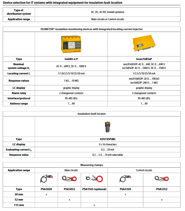
|Series models | Adaptation scenarios | Core subtypes | Positioning current injector | Measurement clamp models | Rated voltage range|
|EDS3090 | Main Circuit | 3090/3090 PG/3090PG-13 | PGH185(230V)/PGH185-13(90-132V) | PSA3020(20mm)/PSA3052(52mm) | AC 20-575V/DC 20-504V(AGE185 Extended to AC 500-790V/DC 400-960V)|
|EDS3091 | Control Circuit | 3091/3091 PG/3091PG-13 | PGH183(230V)/PGH183-13(90-132V) | PSA3320(20mm)/PSA3352(52mm) | AC 20-265V/DC 20-308V |
|EDS3092PG | Main circuit+Control circuit | No subtypes | PGH183+PGH185 | PSA30 series+PSA33 series | Coverage of 3090+3091 voltage range|
|EDS3096 | Main Circuit+Photovoltaic System | 3096 PG/3096PG-13/3096PV | PGH186(230V)/PGH186-13(90-132V) | PSA3020/PSA3052(3096PV Including 2 PSA3052) | AC 0-575V/DC 0-504V (supporting full pole isolation IT system)|
Detailed explanation of core components
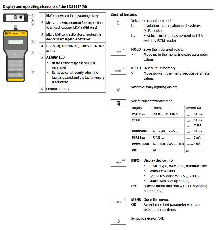
EDS195P (M) Insulation Fault Locator (System Core)
Function: Switching measurement modes (insulation fault location/residual current measurement), data display and storage, parameter adjustment.
Key features: 3-line 16 character backlit LCD display screen, supporting HOLD data retention and RESET fault memory clearing; Only the "M" suffix model (EDS195PM) has an oscilloscope measurement signal output interface.
Power supply: 3 NiMH R6 AA rechargeable batteries (1.2V, ≥ 2000mAh, battery life ≤ 150h), 3 LR6 AA batteries, or powered through Micro USB interface (5V DC), power consumption ≤ 0.5W.
Protection and size: IP40 protection, ABS shell (UL94 V-0 flame retardant), size 84 × 197 × 30mm, weight ≤ 350g.
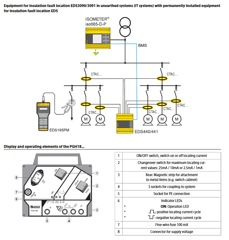
PGH18 series positioning current injector (positioning signal generation)
Model differences and parameters:
|Model | Adaptation Scenario | Power Supply Voltage | Maximum Positioning Current | Positioning Voltage (PGH186)|
|PGH183 | Control Circuit | 230V AC/90-132V AC (-13 subtype) | 1mA/2.5mA (optional) | -|
|PGH185 | Main Circuit | 230V AC/90-132V AC (-13 subtype) | 10mA/25mA (optional) | -|
|PGH186 | Main Circuit/Photovoltaic System | 230V AC/90-132V AC (-13 subtype) | 10mA/25mA (optional) | Built in 50V DC (suitable for power-off/low voltage systems)|
Operation: Includes ON/OFF switch, current gear switch, back with magnetic strip (attached to metal cabinet), equipped with running/current cycle indicator light.
Measurement pliers and couplers
Measuring pliers:
|Model | Jaw diameter | Adaptation scenario | Measurement range | Weight|
|PSA3020/PSA3320 | 20mm | Main circuit/control circuit | PSA30: 10A/10mA; PSA33:1A/0.1mA | ≤300g |
|PSA3052/PSA3352 | 52mm | Main circuit/control circuit | Corresponding model as above | ≤ 700g|
|PSA3165 | 115mm (optional) | Main circuit (thick cable) | 10A/10mA | ≤ 1300g|
|CTAF kit (optional) | Flexible strap (500/1000mm) | Narrow space/large-sized cable | 25mA-50mA | -|
AGE185 coupler (optional): expands the system voltage range to AC 500-790V/DC 400-960V, IP30 protection, weight ≤ 200g, size 88.5 × 42 × 21mm.
Key technical parameters and performance
Measurement performance parameters | Measurement mode | Measurement range | Adjustment accuracy | Frequency range || Insulation fault location (main circuit) | 2-10mA (response value adjustable) | ± 30%/± 2mA | AC 42-460Hz | Insulation fault location (control circuit) | 0.2-1mA (response value adjustable) | ± 30%/± 0.2mA | AC 42-460Hz | Residual current measurement (PSA30 series pliers) | 10mA-10A | 42-60Hz: ± 5%; 61-1000Hz: ± 20% | AC 42-1000Hz | | Residual current measurement (PSA33 series clamp) | 5mA-1A | Same accuracy as above | AC 42-1000Hz|
Environmental and safety parameters
Working temperature: -10 ℃~+55 ℃
Climate rating (IEC 60721): Station use 3K22, transportation 2K11, long-term storage 1K22
Mechanical grade (IEC 60721): Stationary use 3M11, transportation 2M4, long-term storage 1M12
Safety standards: comply with IEC 61010-2-030, DIN VDE 0100-410, EN 61557-9, etc
Protection level: Core component IP40, AGE185 coupler IP30
Operation and usage characteristics
Core operating mode
Insulation fault location mode (EDS mode): suitable for IT systems, generating location current through PGH18 injector, measuring clamp detecting current distribution to locate fault points.
Residual current measurement mode (RCM mode): suitable for TN/TT systems, directly measuring the residual current of the line. When it exceeds the set response value, the ALARM LED flashes.
Key operational functions
Menu adjustment: Select the type of measuring clamp, adjust the response value, and switch the display lighting through the control button.
Data management: Hold button to save measurement values, RESET button to clear fault memory, INFO button to view device information (model, software version, etc.).
Alarm indication: When the response value exceeds the limit, the ALARM LED flashes, and the LED stays on when the fault is cleared and the fault memory is activated.
Ordering and Delivery
Standard components: Each model includes EDS195PM locator, corresponding PGH injector, adaptive measuring pliers, USB power adapter+USB cable, aluminum chassis, and operation manual.
Optional accessories and codes:
|Accessory Name | Function Description | Accessory Code|
|AGE185 coupler | Extended voltage range | B980305|
|PSA3165 measuring pliers | 115mm large clamp, suitable for thick cables | B980852|
|CTAF Flexible Clamp Set | Includes 500/1000mm Flexible Tape, BNC Cable, etc. | B98080220|
|EDS-SET kit | BNC T-connector+2 BNC cables (diode isolation system fault location) | B91082007|
Model coding rule: Taking "EDS3096PG-13" as an example, "3096" is the basic model (main circuit+photovoltaic), "PG" indicates the presence of PGH186 injector, and "-13" indicates the supply voltage of 90-132V AC.
Key issues
Question 1: There is a clear distinction between the adaptation scenarios of different models of the EDS309 series. How to choose the appropriate model based on actual applications (main circuit/control circuit/photovoltaic system)?
Answer: The core selection criteria are "application scenario+system voltage+whether there is a built-in positioning current injector", and the specific logic is as follows:
Main circuit scenario (AC 20-575V/DC 20-504V):
The system has installed a positioning current injector/insulation monitoring device with injection function: select EDS3090 (without built-in injector).
System without injector: Choose EDS3090PG (230V power supply) or EDS3090PG-13 (90-132V power supply).
Photovoltaic system/fully isolated IT system/power outage system: EDS3096PG/PG-13 (including PGH186 injector, built-in 50V positioning voltage) is selected, and EDS3096PV is selected for photovoltaic specific use.
Control circuit scenario (AC 20-265V/DC 20-308V):
The system has installed an injector: select EDS3091; No injector: Choose EDS3091PG (230V) or EDS3091PG-13 (90-132V).
Need to cover both the main circuit and control circuit simultaneously: choose EDS3092PG (including PGH183+PGH185 dual injectors, compatible with two types of scene measurement pliers).
Question 2: Which power supply systems are the insulation fault location and residual current measurement functions of EDS309 series applicable to? What are the core measurement parameters and accuracy?
Answer: The functional adaptation system, core parameters, and accuracy are clearly distinguished as follows:
Measurement Function Adaptation System Core Measurement Parameters Measurement Accuracy
Insulation fault location IT system (live/power-off) response value: 2-10mA for main circuit (default 5mA), 0.2-1mA for control circuit (default 0.5mA); Positioning current: 0.2-25mA (adjustable with injector model) Main circuit: ± 30%/± 2mA; Control circuit: ± 30%/± 0.2mA
Residual current measurement TN/TT system (grounding system) measurement range: PSA30 series clamp 10mA-10A, PSA33 series clamp 5mA-1A; Response value: 10mA-10A (default 100mA) 42-60Hz: ± 5%; 61-1000Hz:±20%; Lag by 20%
Additional explanation: Insulation fault location needs to be used in conjunction with PGH series injectors, and residual current measurement can be directly achieved by connecting EDS195PM with measuring pliers. Both support frequency ranges of 42-460Hz (insulation location)/42-1000Hz (residual current).
Question 3: What are the key operating precautions and accessory selection points when using EDS309 series equipment?
Answer: The key considerations and key points for selecting accessories are as follows:
Precautions for operation:
Voltage Expansion: When the system voltage exceeds AC 575V/DC 504V, it must be paired with AGE185 coupler, otherwise it may damage the equipment.
Measurement clamp matching: The main circuit requires PSA30 series clamps (maximum measurement 50mA), and the control circuit requires PSA33 series clamps (maximum measurement 5mA), which cannot be mixed.
Power supply and battery life: Prioritize using NiMH rechargeable batteries (battery life ≤ 150h), and remove the battery for long-term storage; USB power supply only supports 5V DC, avoid using non-standard adapters.
Safety regulations: Measurement must comply with CAT III (AC 600V)/CAT IV (AC 300V) level requirements and avoid use in corrosive gas and strong vibration environments.
Key points for accessory selection:
Large size cables/narrow spaces: Choose PSA3165 (115mm clamp) or CTAF flexible clamp set (500/1000mm flexible strap).
Fault location of diode isolation system: Additional EDS-SET kit (BNC T-shaped connector+dedicated cable) is required.
Oscilloscope linkage analysis: EDS195PM model (with measurement signal output interface) needs to be selected, paired with BNC-PS2 adapter cable.
- YOKOGAWA
- Reliance
- ADVANCED
- SEW
- ProSoft
- WATLOW
- Kongsberg
- FANUC
- VSD
- DCS
- PLC
- man-machine
- Covid-19
- Energy and Gender
- Energy Access
- Renewable Integration
- Energy Subsidies
- Energy and Water
- Net zero emission
- Energy Security
- Critical Minerals
- A-B
- petroleum
- Mine scale
- Sewage treatment
- cement
- architecture
- Industrial information
- New energy
- Automobile market
- electricity
- Construction site
- HIMA
- ABB
- Rockwell
- Schneider Modicon
- Siemens
- xYCOM
- Yaskawa
- Woodward
- BOSCH Rexroth
- MOOG
- General Electric
- American NI
- Rolls-Royce
- CTI
- Honeywell
- EMERSON
- MAN
- GE
- TRICONEX
- Control Wave
- ALSTOM
- AMAT
- STUDER
- KONGSBERG
- MOTOROLA
- DANAHER MOTION
- Bentley
- Galil
- EATON
- MOLEX
- Triconex
- DEIF
- B&W
- ZYGO
- Aerotech
- DANFOSS
- KOLLMORGEN
- Beijer
- Endress+Hauser
- schneider
- Foxboro
- KB
- REXROTH
- YAMAHA
- Johnson
- Westinghouse
- WAGO
- TOSHIBA
- TEKTRONIX
- BENDER
- BMCM
- SMC
- HITACHI
- HIRSCHMANN
- XP POWER
- Baldor
- Meggitt
- SHINKAWA
- Other Brands
- UniOP
- KUKA
- IBA
- Beckhoff
-
Basler Electric DECS-250-CN1SN1N Automatic Voltage Regulator for Generator Excitation Control
-
ADLINK CPCI-6860A - 51-31310-OB10 industrial motherboard CompactPCI SBC
-
ADLINK AmITX-SL-G-H110 - 51-7A104-0A30 Mini-ITX Industrial Motherboard
-
ADLINK PXI-2005-003 - CPCI Industrial PC Data Acquisition Card Multi-Function DAQ
-
ADLINK DININ-814M - 51-14032-0A3D SCSI-100P cable connection Interface Terminal Board
-
ADLINK CPCI-3920NA/C2D15/M1G - 3U CompactPCI Intel Core 2 Duo Single Board Computer
-
ADLINK PCIE-8560 - 51-18014-0A20 Communication Card High Speed DAQ
-
ADLINK PCI-C154+ - Motion Control Card 4-axis Motion Controller Board
-
ADLINK PCI-RTV24 - image capture card Analog Video Frame Grabber
-
ADLINK NuPRO-842LV/P - 51-41360-0B30 Industrial Motherboard CPU Board
-
ADLINK cBP-3208/3208R - CPCI Board 3U 8-Slot CompactPCI Backplane
-
ADLINK PCI-8164 - 4-Axis Motion Controller PCI Card 51-12406-0A40
-
ADLINK PCIe-GIE64+ - 4-CH GigE Vision PoE+ Frame Grabber Video Capture Card
-
ADLINK CPCI-6860 / 6860A - CompactPCI Dual Xeon Single Board Computer
-
ADLINK IEC-915GV - REV 1.1 Industrial motherboard CPU Board
-
ADLINK ND-6520 - Technology RS-232 to RS-422RS-485 Converter NuDAM Module
-
ADLINK RTV-24 / PCI-MP4S - 51-12519-1C30 4-Channel Real Time Video Capture Board
-
ADLINK cPCI-6910 / cPCI-6910AM/M1G - cPCI-6910AM/DXL16/M1G/S80G(G)-3120 BOARD CompactPCI SBC
-
ADLINK NUPRO-A40H - Linghua 51-41807-1A30 Industrial Control Computer Motherboard
-
ADLINK USB-3488A - USB to GPIB INTERFACE USB-3488A(G) Controller Module
-
ADLINK PCI-8134A - motion control card 4-Axis Controller Card
-
ADLINK PCI-7432 - Board 32-Channel input / 32-output Isolated Digital I/O PCI Card
-
ADLINK PCI-8134A - 51-12421-0A10 motion controller card tested
-
ADLINK LPCIe-7230 - 32 CH Isolated Input/output Card 2 Interrupts Low Profile PCIe
-
ADLINK NuPRO-E340 - industrial computer motherboard 51-47807-0A30 PICMG 1.3 SHB
-
ADLINK PCI-7434 - High-speed Digital Acquisition Card 64-CH Isolated DO Card
-
ADLINK NuPRO-E330 - 51-41805-0A20 Indsutrial Board SHB Single Board Computer
-
ADLINK PCI-7248 - OPTO-22 48 CHANNEL DIO DIGITAL TTL/DTL I/O 51-12006-0A40 GP
-
ADLINK PCI-8134 - Motion control card 4-Axis Controller Card
-
ADLINK AMP-208C - Movimiento Control Tarjeta 51-12420-1A20 W/Expansión & Breakout
-
ADLINK PCI-8164 - 51-12406-0A40 PCB Board 4-Axis Motion Controller Card
-
ADLINK DIN-68Y-SGII / DIN-68M-J3A - Terminal Board Connector Interface Block
-
ADLINK PCIe-7432 - Technology 51-18402-0A10 PCIe Card With High Input Range
-
ADLINK PCI-8144 / PCI-8144N - Motion control card 4-Axis Stepper Controller Card
-
ADLINK HSL-HUB3/REPEATER - HIGH SPEED LINK EXTENSION MODULES Distributed Hub Module
-
ADLINK ND-6017 - Data Logging + Acquisition 8CH A/D input Mod NuDAM Module
-
ADLINK LPCIe-7250 - data acquisition card Low Profile 8-CH Relay Output Card
-
ADLINK PCI-7432 - I/O card 64-CH Isolated Digital Input Output PCI Card
-
ADLINK IMB-M43H - industrial control computer motherboard Q87 Chip Micro-ATX
-
ADLINK MP-C154 - Motion control Card 4-Axis Motion Controller Board
-
ADLINK PCI-RTV24 - image capture card Video Frame Grabber Card
-
ADLINK PCI-7250 - 8-CH Relay Output & 8-CH Isolated DI Card
-
ADLINK PCI-6308V - 8-CH 12-Bit Isolated Analog Output PCI Card PCB-I-E-1148=6EX2
-
ADLINK PCI-7248 - capture card 48-CH Opto-22 Compatible DIO Card
-
ADLINK HSL-AI16A02-M-VV - Analog Input Output Distributed Module
-
ADLINK NuPRO-A301 - Rev:1.4 NUPRO-A301 PICMG Full-Size Single Board Computer
-
ADLINK PCI-6208V-GL - 8-CH Voltage Analog Output PCI Card
-
ADLINK PCI-8134A - 51-12421-0A10 4-Axis Motion Controller Card
-
ADLINK MNET-S23 - TECHNOLOGY MNET S23 - SERVO DRIVER CONTROL MODULE
-
ADLINK M-342 - ATX I3 I5 I7 Q67 Industrial Motherboard
-
ADLINK NUPRO-780 - Industrial Motherboard CPU Board PICMG SBC
-
ADLINK MP-C154 / MP-C152 - 4-Axis Motion Control Card Pulse-Train Controller
-
ADLINK NuPRO-935A/LV10B0 - Motherboard 51-41802-0A10 GP w/RAM Industrial Control Board
-
ADLINK MP-C154 - Motion control card 4-Axis Motion Controller Mainboard
-
ADLINK PCI-7250 - PCI Acquisition Card 8-CH Relay Output Isolated DI Card
-
ADLINK ACL-7124 - Technology Inc.24 DIO Card Digital Input Output Card
-
ADLINK PCI-8554 A2 - Timer/Counter Data Acquisition Card
-
ADLINK DIN-825-GP4 - Terminal Block Interface Board Breakout Module
-
ADLINK NuPR0-761 - REV:1.1 Industrial motherboard Full-Size PICMG SBC
-
ADLINK MXE-1401/M8G (G) - Matrix Fanless Embedded Computer Industrial PC
-
ADLINK HSL-DI16DO16-UD-NN - Digital 16 Channel I/O Mod Distributed I/O Module
-
ADLINK ND6520 - NUDAM INTELLIGENT DA&C MODULE RS232-RS-422/RS485 CONVERTOR
-
ADLINK NUPRO-761 - REV:1.1 Industrial Motherboard CPU Board
-
ADLINK AMP-208C - Motion Control Card 51-12420-1A20 DSP-based 8-axis
-
ADLINK NuPRO-A301REV 1.4 - with packaging industrial computer motherboard PICMG SBC
-
ADLINK PCM-9112+ - 51-12300-0A2 industrial motherboard Multi-Function DAQ PC/104 Module
-
ADLINK PCM-7250+ - 8-CH Relay Outputs & 8-CH Isolated DI Module PC/104
-
ADLINK PCI-RTV24 - Image capture card Analog Video Frame Grabber
-
ADLINK PCI-8134 - Motion Controller PCI Card 4-Axis Controller Board
-
ADLINK PCI-7432 - Isolated Digital I/O PCI Card
-
ADLINK PCI-8554 A2 - acquisition card Timer/Counter Card
-
ADLINK PCI-8132 - Rev.A2 2-Axis Servo & Stepper Motion Controller Card
-
ADLINK PCI-8132 - Data Acquisition card 2-Axis Motion Controller Card
-
ADLINK EBP-13E4 - 51-46703-0A30 Industrial Backplane Board Passive Backplane
-
ADLINK PCI-800L - Electronic Card Interface Controller Card
-
ADLINK PCIe-GIE72 - 51-18531-0A10 PCB Board GigE Vision Frame Grabber
-
ADLINK DAQ-2010(G)-OOBO - Simultaneous-Sampling Multi-Function DAQ Card
-
ADLINK PCI-9112 - REV.B1 Multifunction DAQ Card Data Acquisition Card
-
ADLINK PCI-7230 - 51-12003-DA60 32-CH Isolated Digital I/O Card
-
ADLINK PCI-7432 - Data Acquisition Card Isolated Digital I/O PCI Card
-
ADLINK ETX-AT-N270-18/LXE - 51-71111-0A20 ETX CPU Module Motherboard
-
ADLINK HSL-DI32-UD-N - DIGITAL INPUT 32 POINTS MODULE Distributed I/O
-
ADLINK AMP-204C - Motion Control card DSP-Based 4-Axis Advanced Controller
-
ADLINK MNET-4XMOG-0050 - Four-axis Motion Controller Distributed Motion Module
-
ADLINK AMP-204C - Motion control card DSP-Based 4-Axis Pulse-Train Controller
-
ADLINK PCI-7442 - Switch card 64-Channel Datalogging & Acquisition Card
-
ADLINK M-302 - Industrial control motherboard ATX PC Board
-
ADLINK NUPRO-852 / NUPRO-852LV - Industrial motherboard Single Board Computer
-
ADLINK PCI-8134 - REV.B1. 4-Axis Motion Controller Card
-
ADLINK PCI-GIE62 + - 51-18502-0A20 2-CH GigE Vision Frame Grabber PoE Card
-
ADLINK PCI-MPG24 - 51-12523-0B20 MPEG4 Card Video Compression Hardware
-
ADLINK HSL-TB32-M-DIN - 32-CH I/O TERMINAL W/ HSL-AI16AO2-M-VV MODULE
-
ADLINK PCI-M114-GL - PCB Ver 2.1 Motion Controller Axis Card
-
ADLINK IMB-M40H - SYM76996H61 motherboard Industrial Computer Mainboard
-
ADLINK NUPRO-A40H - 51-41807-1A20 industrial control motherboard H61 Chip
-
ADLINK PCI-M114-GL - Axis Card Data Acquisition Card PCB VER2.2 Motion Controller
-
ADLINK PCI-8134 - Motion Controller PCI Card 4-Axis Controller Board
-
ADLINK PCI-8102 - Motion control card 2-Axis Servo & Stepper Controller
-
ADLINK NuPRO-841REV:3.0 - motherboard Industrial Control PC Board
-
ADLINK HSL-TB32-U-DIN REV A1 - Breakout Terminal Board Field I/O Module
-
ADLINK AMP-204C - Motion Control card DSP-Based 4-Axis Pulse-Train Controller
-
ADLINK NUPRO-A40H - 51-41807-1A20 industrial control motherboard H61 PC Board
-
ADLINK PCI-6308A / PCI-6308V - 51-12202-0A50 Isolated Analog Output Card
-
ADLINK AMP-204C - DSP-Based 4-Axis Advanced Pulse-Train Motion Controller
-
ADLINK PCI-7434 - Technology 64-Channel Isolated Digital I/O PCI Cards
-
ADLINK CPCI-6840 / CPCI-6840V / PM16/M1G-12G0 - CompactPCI Single Board Computer CPU Module
-
ADLINK PCIE-GIE74 - Motherboard Video Capture Card 51-18531-0A10 Frame Grabber
-
ADLINK NuPRO-E330 - industrial computer equipment motherboard Control Mainboard
-
ADLINK AMP-208C / 51-12420-1A20 - Motion Control Card W/ Expansion & Breakout Board
-
ADLINK HPCI-14S12U - industrial computer baseboard Passive Backplane 14 Slots
-
ADLINK PCI-8164 - 4-Axis Motion Controller PCI Card W/ 1x Cable, 1x Breakout Box
-
ADLINK PCIe-RTV24 - 51-18016-0A20 Image Acquisition Video Capture Card
-
ADLINK M-342 - 5 PCI ATX Motherboard Industrial PC Mainboard
-
ADLINK PCI-FIW64 - 4/2 Channel IEEE1394B Image Capture Card FireWire Frame Grabber
-
ADLINK PCI-7432 - digital IO card 64-CH Isolated Digital Input Output Card
-
ADLINK 51-12001-0C20 - Circuit Board PCI-7200 Data Acquisition Controller Card
-
ADLINK PXI-3920 - PXI 3U cPCI Industrial Controller Embedded System CPU Board
-
ADLINK NuPRO-841REV:2.0 - motherboard Industrial Control PC Board
-
ADLINK NuPro-E330 - 51-41805-0A20 PCB Industrial Control Computer Motherboard
-
ADLINK PCI-RTV24 - Image capture card Analog Video Frame Grabber
-
ADLINK PCI-7442 - Switch card 64-Channel Datalogging & Acquisition Card
-
ADLINK HPX-13S4 - device baseboard Passive Backplane Riser Card
-
ADLINK PCI-9112 REV A.1 - Multi Function DA&C Board Data Acquisition Card
-
ADLINK PCI-7248 - 51-12006-0A40 Card Control 48-CH Digital I/O Module
-
ADLINK CPCI-6860 / 6860A - motherboard CompactPCI Dual Xeon Single Board Computer
-
ADLINK DPAC-3020-11(G) - Embedded PC Automation Controller Machine Control Board
-
ADLINK NuPRO-841 REV:1.0 - industrial control motherboard CPU Board
-
ADLINK MNET-4XMOG-0050 - Four-axis Motion Controller MNET Motion Control Card

K-JIANG

Add: Jimei North Road, Jimei District, Xiamen, Fujian, China
Tell:+86-15305925923