
K-WANG


Watlow EZ-ZONE ® RME (Expansion) Module
Watlow EZ-ZONE ® RME (Expansion) Module
Product basic information and positioning
1. Core positioning
As the I/O expansion core of the RM system, it does not have independent PID control function and focuses on supplementing digital/analog I/O interfaces, providing logical operations, timing and counting, special equipment control (compressor/valve/sequencer) and other functions. It can be networked with RM series modules such as RMC (controller) and RMA (communication gateway), and supports up to 17 modules (1 RMA+16 other RM modules) to work together.
2. Basic specifications
Appearance and Installation: DIN rail installation (EN50022 standard), size 155mm × 116.08mm, weight 453.59g, requires vertical installation, reserves 76.2mm maintenance space, supports rail/panel installation methods.
Power supply requirements: 20.4-30.8V AC/DC, Class 2 or SELV certified power supply, power consumption 7W/14VA, supporting Semi F47-0200 voltage drop standard.
Environmental adaptability: Operating temperature -18~65 ° C, storage temperature -40~85 ° C, 0-90% RH (non condensing), protection level IP20, required to be installed in NEMA Type 1 or above protective enclosures.
Certification standards: UL/EN 61010, Class 1 Div. 2 (optional) RoHS、WEEE、CE, Some models have passed FM Class 3545 certification.
Warranty and Support: 3-year warranty (non misuse scenario), technical support can be obtained through phone, email or local representative, and RMA number needs to be applied for in advance for returns.
Core functions and technical features
1. I/O expansion function
(1) Input type and specifications
Digital input: up to 24 channels, supporting dry contact/DC voltage input (low state<2V, high state>3V), dry contact closing resistance<50 Ω, open circuit resistance>100K Ω.
Current Transformer (CT) Input: Up to 16 channels, input range 0-50mA AC, compatible with 16-0246 CT models, accuracy ± 1mA, response time ≤ 1 second.
(2) Output type and specifications
Applicable scenarios for key parameters of output types
Digital output (open collector) maximum 32V DC, single channel 1.5A, total sink current 8A, small relay drive, sensor power supply
Mechanical relay 5A/240V AC, Form A contact, 100000 cycle life, high-power equipment switch control
Solid state relay (SSR) 2A/20-264V AC (4 channels) or 10A/240V AC (2 channels) high-frequency switch load (heater, motor)
Process/retransmission output 0-10V DC (minimum 4k Ω load) or 0-20mA DC (maximum 400 Ω load) signal retransmission, valve positioner control
2. Control and calculation functions
(1) Basic control module
Logical operation: 16 logical instances, supporting 8 logical relationships such as AND/OR/NOT/XOR, and can access up to 8 input sources.
Timing function: 8 timer instances, supporting pulse/delay/single trigger/hold timing, with a time range of 0-9999 seconds.
Counting function: 8 counter instances, supporting increasing and decreasing counting, load value setting, target value triggering output, counting range 0-9999.
Mathematical operations: 8 mathematical examples, supporting 16 operations such as addition, subtraction, multiplication, division, mean, maximum/minimum, square root, etc., and supporting multiple input source combinations.
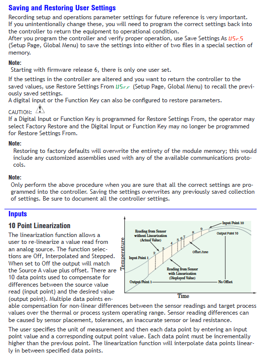
Linearization: 8 linearization instances, 10 point linearization calibration, suitable for non-standard sensor signal correction.
(2) Special equipment control
Compressor control: Supports linkage of 1-2 control circuits, with adjustable start stop thresholds and minimum start stop times to avoid frequent start stop wear.
Electric valve control: supports valve fully open/fully closed control, configurable travel time and dead zone, suitable for two-wire valve drive.
Sequencer control: distributes a single power signal into 4 outputs, supports linear/cyclic output sequence, and balances load wear.
3. Communication and Networking
(1) Support agreement
Standard configuration: Watlow Standard Bus (EIA-485), used for inter module communication, supports 17 nodes.
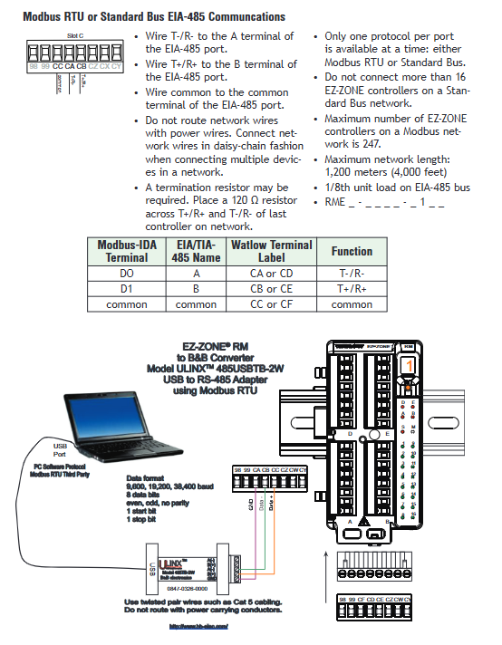
Optional: Modbus RTU (EIA-485/232), requires model configuration, supports 247 nodes, baud rate 9600/19200/38400bps.
Extension Protocol: Supports industrial buses such as EtherNet/IP, DeviceNet, PROFIBUS DP, etc. through RMA module.
(2) Networking standards
Topology: EIA-485 adopts a daisy chain topology, with 120 Ω terminal resistors connected at the beginning and end.
Distance limit: EIA-485 maximum 1200 meters (shielded twisted pair), EIA-232 maximum 15 meters.
Anti interference: Communication lines and power lines should be wired separately (with a spacing of ≥ 10cm), using shielded twisted pair cables, and the shielding layer should be grounded at one end.
4. Alarm and safety functions
Alarm function: 8 alarm instances, supporting process alarm/deviation alarm, configurable high and low alarm points, hysteresis, and locking/non locking modes.
Safety features: Class 1 Div. 2 models support use in hazardous areas (temperature code T4), require the use of certified components, and prohibit live plugging and unplugging of wiring.
Permission management: Supports user/administrator two-level passwords, with optional rolling passwords (automatically changed after power failure) to prevent unauthorized operations.
Installation and Wiring Guide
1. Installation process
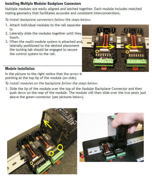
Rail installation: The hook is fixed to the 35mm rail and the rotating buckle is locked; When splicing multiple modules horizontally, ensure that the backplane bus is fully in contact.
Rail installation: Connect two rails through Inter module Bus, with a maximum distance of 200 feet, and require independent power supply to avoid voltage drop. The communication line uses shielded twisted pair.
2. Wiring specifications
(1) Core terminal definition
Power terminal (Slot C, 98/99): 98+, 99-, AC/DC polarity should be distinguished and reverse connection is prohibited.
Communication terminal (Slot C): CF (common terminal) CD(T-/R-)、CE(T+/R+), Used for Standard Bus/Modbus RTU communication.
I/O terminals (Slot A/B/D/E): Configure corresponding digital I/O, relay output, and process output terminals according to the model, and refer to the terminal table corresponding to the model for detailed definition.
(2) Wiring requirements
Wire specifications: Supports 12-30 AWG single/multi strand copper wire, with a stripping length of 7.6mm and a terminal torque of 0.56 Nm (right angle terminal)/0.5 Nm (front terminal).
Electrical isolation: Digital I/O and process outputs need to be electrically isolated from power lines to prevent grounding loops (grounding resistance ≤ 4 Ω).
Inductive load: When driving inductive loads such as relay coils and solenoid valves, RC suppressors or freewheeling diodes need to be connected in series.
3. Typical networking examples
Single rail I/O expansion: 1 RMA (communication gateway)+1 RMC (controller)+2 RME (expansion), RME provides digital I/O access to sensors/actuators, and communicates with RMC through Standard Bus.
Track based distributed control: Two rails are deployed with RME modules respectively, connected through Inter module Bus, sharing control logic and reducing on-site wiring length.
Operation and Configuration Guide
1. Menu and Operation
Configure through RUI (Remote User Interface) or EZ-ZONE Configurator software, with three levels of menus:
Operations page: View I/O status, alarm status, timing/counting results, etc.
Setup page: Configure core parameters such as I/O direction, logical relationships, timing parameters, alarm thresholds, etc.
Factory page: Configure security permissions, calibration parameters, device information, etc., requiring administrator privileges.
2. Software Configuration (EZ-ZONE Configurator)
Connection method: Connect the module's Standard Bus terminal through a USB-EIA-485 converter, and the software will automatically scan the RM module in the network.
Core configuration: It can configure I/O functions, logical operation relationships, communication parameters, alarm rules, etc., and supports configuration file backup and batch import.
Maintenance and troubleshooting
1. Daily maintenance
Regular inspection: Check the terminal fastening, wiring integrity, and module indicator light status (Power/Comm light is normally green) every month.
Cleaning and maintenance: Wipe the shell with a dry cloth to avoid corrosive cleaning agents; SD card (if available) regularly backs up data to prevent full storage.
Spare parts management: Class 1 Div. 2 models require the use of original factory certified spare parts, and it is prohibited to replace components arbitrarily.
2. Common faults and solutions
Possible causes and solutions for the fault phenomenon
Communication failure address/baud rate mismatch, wiring error, terminal resistance not connected. Check communication parameters, check EIA-485 polarity, and connect 120 Ω resistors to the front and rear modules
Output unresponsive I/O direction configuration error, load overload, relay/SSR damage, reconfigure I/O direction, check load current, replace damaged components
Alarm does not trigger alarm threshold setting error, alarm source selection error, alarm blocking enable correction alarm threshold, select correct alarm source, disable unnecessary alarm blocking
Abnormal counting/timing trigger signal not connected, incorrect trigger level setting, check trigger signal wiring, adjust trigger level (high/low state)
Typical application scenarios
Industrial equipment I/O expansion: Supplement digital I/O to RMC controllers, connect temperature sensors, limit switches, solenoid valves and other devices, and achieve multi device linkage control.
Distributed control networking: In the track configuration, RME is deployed on site, connected to nearby device I/O, and communicates with the control room controller through the bus to reduce wiring costs.
Special equipment control: achieve stable operation of the refrigeration system through compressor control function, or adjust fluid flow through electric valve control, suitable for HVAC, chemical and other scenarios.
Logic and timing control: Equipment interlocking (such as pump and valve linkage) is achieved through logical operations, and delayed start stop is achieved through timing function, which is suitable for production line process control.
- YOKOGAWA
- Reliance
- ADVANCED
- SEW
- ProSoft
- WATLOW
- Kongsberg
- FANUC
- VSD
- DCS
- PLC
- man-machine
- Covid-19
- Energy and Gender
- Energy Access
- Renewable Integration
- Energy Subsidies
- Energy and Water
- Net zero emission
- Energy Security
- Critical Minerals
- A-B
- petroleum
- Mine scale
- Sewage treatment
- cement
- architecture
- Industrial information
- New energy
- Automobile market
- electricity
- Construction site
- HIMA
- ABB
- Rockwell
- Schneider Modicon
- Siemens
- xYCOM
- Yaskawa
- Woodward
- BOSCH Rexroth
- MOOG
- General Electric
- American NI
- Rolls-Royce
- CTI
- Honeywell
- EMERSON
- MAN
- GE
- TRICONEX
- Control Wave
- ALSTOM
- AMAT
- STUDER
- KONGSBERG
- MOTOROLA
- DANAHER MOTION
- Bentley
- Galil
- EATON
- MOLEX
- Triconex
- DEIF
- B&W
- ZYGO
- Aerotech
- DANFOSS
- KOLLMORGEN
- Beijer
- Endress+Hauser
- schneider
- Foxboro
- KB
- REXROTH
- YAMAHA
- Johnson
- Westinghouse
- WAGO
- TOSHIBA
- TEKTRONIX
- BENDER
- BMCM
- SMC
- HITACHI
- HIRSCHMANN
- XP POWER
- Baldor
- Meggitt
- SHINKAWA
- Other Brands
- UniOP
- KUKA
- IBA
- Beckhoff
-
ADLINK CPCI-6860A - 51-31310-OB10 industrial motherboard CompactPCI SBC
-
ADLINK AmITX-SL-G-H110 - 51-7A104-0A30 Mini-ITX Industrial Motherboard
-
ADLINK PXI-2005-003 - CPCI Industrial PC Data Acquisition Card Multi-Function DAQ
-
ADLINK DININ-814M - 51-14032-0A3D SCSI-100P cable connection Interface Terminal Board
-
ADLINK CPCI-3920NA/C2D15/M1G - 3U CompactPCI Intel Core 2 Duo Single Board Computer
-
ADLINK PCIE-8560 - 51-18014-0A20 Communication Card High Speed DAQ
-
ADLINK PCI-C154+ - Motion Control Card 4-axis Motion Controller Board
-
ADLINK PCI-RTV24 - image capture card Analog Video Frame Grabber
-
ADLINK NuPRO-842LV/P - 51-41360-0B30 Industrial Motherboard CPU Board
-
ADLINK cBP-3208/3208R - CPCI Board 3U 8-Slot CompactPCI Backplane
-
ADLINK PCI-8164 - 4-Axis Motion Controller PCI Card 51-12406-0A40
-
ADLINK PCIe-GIE64+ - 4-CH GigE Vision PoE+ Frame Grabber Video Capture Card
-
ADLINK CPCI-6860 / 6860A - CompactPCI Dual Xeon Single Board Computer
-
ADLINK IEC-915GV - REV 1.1 Industrial motherboard CPU Board
-
ADLINK ND-6520 - Technology RS-232 to RS-422RS-485 Converter NuDAM Module
-
ADLINK RTV-24 / PCI-MP4S - 51-12519-1C30 4-Channel Real Time Video Capture Board
-
ADLINK cPCI-6910 / cPCI-6910AM/M1G - cPCI-6910AM/DXL16/M1G/S80G(G)-3120 BOARD CompactPCI SBC
-
ADLINK NUPRO-A40H - Linghua 51-41807-1A30 Industrial Control Computer Motherboard
-
ADLINK USB-3488A - USB to GPIB INTERFACE USB-3488A(G) Controller Module
-
ADLINK PCI-8134A - motion control card 4-Axis Controller Card
-
ADLINK PCI-7432 - Board 32-Channel input / 32-output Isolated Digital I/O PCI Card
-
ADLINK PCI-8134A - 51-12421-0A10 motion controller card tested
-
ADLINK LPCIe-7230 - 32 CH Isolated Input/output Card 2 Interrupts Low Profile PCIe
-
ADLINK NuPRO-E340 - industrial computer motherboard 51-47807-0A30 PICMG 1.3 SHB
-
ADLINK PCI-7434 - High-speed Digital Acquisition Card 64-CH Isolated DO Card
-
ADLINK NuPRO-E330 - 51-41805-0A20 Indsutrial Board SHB Single Board Computer
-
ADLINK PCI-7248 - OPTO-22 48 CHANNEL DIO DIGITAL TTL/DTL I/O 51-12006-0A40 GP
-
ADLINK PCI-8134 - Motion control card 4-Axis Controller Card
-
ADLINK AMP-208C - Movimiento Control Tarjeta 51-12420-1A20 W/Expansión & Breakout
-
ADLINK PCI-8164 - 51-12406-0A40 PCB Board 4-Axis Motion Controller Card
-
ADLINK DIN-68Y-SGII / DIN-68M-J3A - Terminal Board Connector Interface Block
-
ADLINK PCIe-7432 - Technology 51-18402-0A10 PCIe Card With High Input Range
-
ADLINK PCI-8144 / PCI-8144N - Motion control card 4-Axis Stepper Controller Card
-
ADLINK HSL-HUB3/REPEATER - HIGH SPEED LINK EXTENSION MODULES Distributed Hub Module
-
ADLINK ND-6017 - Data Logging + Acquisition 8CH A/D input Mod NuDAM Module
-
ADLINK LPCIe-7250 - data acquisition card Low Profile 8-CH Relay Output Card
-
ADLINK PCI-7432 - I/O card 64-CH Isolated Digital Input Output PCI Card
-
ADLINK IMB-M43H - industrial control computer motherboard Q87 Chip Micro-ATX
-
ADLINK MP-C154 - Motion control Card 4-Axis Motion Controller Board
-
ADLINK PCI-RTV24 - image capture card Video Frame Grabber Card
-
ADLINK PCI-7250 - 8-CH Relay Output & 8-CH Isolated DI Card
-
ADLINK PCI-6308V - 8-CH 12-Bit Isolated Analog Output PCI Card PCB-I-E-1148=6EX2
-
ADLINK PCI-7248 - capture card 48-CH Opto-22 Compatible DIO Card
-
ADLINK HSL-AI16A02-M-VV - Analog Input Output Distributed Module
-
ADLINK NuPRO-A301 - Rev:1.4 NUPRO-A301 PICMG Full-Size Single Board Computer
-
ADLINK PCI-6208V-GL - 8-CH Voltage Analog Output PCI Card
-
ADLINK PCI-8134A - 51-12421-0A10 4-Axis Motion Controller Card
-
ADLINK MNET-S23 - TECHNOLOGY MNET S23 - SERVO DRIVER CONTROL MODULE
-
ADLINK M-342 - ATX I3 I5 I7 Q67 Industrial Motherboard
-
ADLINK NUPRO-780 - Industrial Motherboard CPU Board PICMG SBC
-
ADLINK MP-C154 / MP-C152 - 4-Axis Motion Control Card Pulse-Train Controller
-
ADLINK NuPRO-935A/LV10B0 - Motherboard 51-41802-0A10 GP w/RAM Industrial Control Board
-
ADLINK MP-C154 - Motion control card 4-Axis Motion Controller Mainboard
-
ADLINK PCI-7250 - PCI Acquisition Card 8-CH Relay Output Isolated DI Card
-
ADLINK ACL-7124 - Technology Inc.24 DIO Card Digital Input Output Card
-
ADLINK PCI-8554 A2 - Timer/Counter Data Acquisition Card
-
ADLINK DIN-825-GP4 - Terminal Block Interface Board Breakout Module
-
ADLINK NuPR0-761 - REV:1.1 Industrial motherboard Full-Size PICMG SBC
-
ADLINK MXE-1401/M8G (G) - Matrix Fanless Embedded Computer Industrial PC
-
ADLINK HSL-DI16DO16-UD-NN - Digital 16 Channel I/O Mod Distributed I/O Module
-
ADLINK ND6520 - NUDAM INTELLIGENT DA&C MODULE RS232-RS-422/RS485 CONVERTOR
-
ADLINK NUPRO-761 - REV:1.1 Industrial Motherboard CPU Board
-
ADLINK AMP-208C - Motion Control Card 51-12420-1A20 DSP-based 8-axis
-
ADLINK NuPRO-A301REV 1.4 - with packaging industrial computer motherboard PICMG SBC
-
ADLINK PCM-9112+ - 51-12300-0A2 industrial motherboard Multi-Function DAQ PC/104 Module
-
ADLINK PCM-7250+ - 8-CH Relay Outputs & 8-CH Isolated DI Module PC/104
-
ADLINK PCI-RTV24 - Image capture card Analog Video Frame Grabber
-
ADLINK PCI-8134 - Motion Controller PCI Card 4-Axis Controller Board
-
ADLINK PCI-7432 - Isolated Digital I/O PCI Card
-
ADLINK PCI-8554 A2 - acquisition card Timer/Counter Card
-
ADLINK PCI-8132 - Rev.A2 2-Axis Servo & Stepper Motion Controller Card
-
ADLINK PCI-8132 - Data Acquisition card 2-Axis Motion Controller Card
-
ADLINK EBP-13E4 - 51-46703-0A30 Industrial Backplane Board Passive Backplane
-
ADLINK PCI-800L - Electronic Card Interface Controller Card
-
ADLINK PCIe-GIE72 - 51-18531-0A10 PCB Board GigE Vision Frame Grabber
-
ADLINK DAQ-2010(G)-OOBO - Simultaneous-Sampling Multi-Function DAQ Card
-
ADLINK PCI-9112 - REV.B1 Multifunction DAQ Card Data Acquisition Card
-
ADLINK PCI-7230 - 51-12003-DA60 32-CH Isolated Digital I/O Card
-
ADLINK PCI-7432 - Data Acquisition Card Isolated Digital I/O PCI Card
-
ADLINK ETX-AT-N270-18/LXE - 51-71111-0A20 ETX CPU Module Motherboard
-
ADLINK HSL-DI32-UD-N - DIGITAL INPUT 32 POINTS MODULE Distributed I/O
-
ADLINK AMP-204C - Motion Control card DSP-Based 4-Axis Advanced Controller
-
ADLINK MNET-4XMOG-0050 - Four-axis Motion Controller Distributed Motion Module
-
ADLINK AMP-204C - Motion control card DSP-Based 4-Axis Pulse-Train Controller
-
ADLINK PCI-7442 - Switch card 64-Channel Datalogging & Acquisition Card
-
ADLINK M-302 - Industrial control motherboard ATX PC Board
-
ADLINK NUPRO-852 / NUPRO-852LV - Industrial motherboard Single Board Computer
-
ADLINK PCI-8134 - REV.B1. 4-Axis Motion Controller Card
-
ADLINK PCI-GIE62 + - 51-18502-0A20 2-CH GigE Vision Frame Grabber PoE Card
-
ADLINK PCI-MPG24 - 51-12523-0B20 MPEG4 Card Video Compression Hardware
-
ADLINK HSL-TB32-M-DIN - 32-CH I/O TERMINAL W/ HSL-AI16AO2-M-VV MODULE
-
ADLINK PCI-M114-GL - PCB Ver 2.1 Motion Controller Axis Card
-
ADLINK IMB-M40H - SYM76996H61 motherboard Industrial Computer Mainboard
-
ADLINK NUPRO-A40H - 51-41807-1A20 industrial control motherboard H61 Chip
-
ADLINK PCI-M114-GL - Axis Card Data Acquisition Card PCB VER2.2 Motion Controller
-
ADLINK PCI-8134 - Motion Controller PCI Card 4-Axis Controller Board
-
ADLINK PCI-8102 - Motion control card 2-Axis Servo & Stepper Controller
-
ADLINK NuPRO-841REV:3.0 - motherboard Industrial Control PC Board
-
ADLINK HSL-TB32-U-DIN REV A1 - Breakout Terminal Board Field I/O Module
-
ADLINK AMP-204C - Motion Control card DSP-Based 4-Axis Pulse-Train Controller
-
ADLINK NUPRO-A40H - 51-41807-1A20 industrial control motherboard H61 PC Board
-
ADLINK PCI-6308A / PCI-6308V - 51-12202-0A50 Isolated Analog Output Card
-
ADLINK AMP-204C - DSP-Based 4-Axis Advanced Pulse-Train Motion Controller
-
ADLINK PCI-7434 - Technology 64-Channel Isolated Digital I/O PCI Cards
-
ADLINK CPCI-6840 / CPCI-6840V / PM16/M1G-12G0 - CompactPCI Single Board Computer CPU Module
-
ADLINK PCIE-GIE74 - Motherboard Video Capture Card 51-18531-0A10 Frame Grabber
-
ADLINK NuPRO-E330 - industrial computer equipment motherboard Control Mainboard
-
ADLINK AMP-208C / 51-12420-1A20 - Motion Control Card W/ Expansion & Breakout Board
-
ADLINK HPCI-14S12U - industrial computer baseboard Passive Backplane 14 Slots
-
ADLINK PCI-8164 - 4-Axis Motion Controller PCI Card W/ 1x Cable, 1x Breakout Box
-
ADLINK PCIe-RTV24 - 51-18016-0A20 Image Acquisition Video Capture Card
-
ADLINK M-342 - 5 PCI ATX Motherboard Industrial PC Mainboard
-
ADLINK PCI-FIW64 - 4/2 Channel IEEE1394B Image Capture Card FireWire Frame Grabber
-
ADLINK PCI-7432 - digital IO card 64-CH Isolated Digital Input Output Card
-
ADLINK 51-12001-0C20 - Circuit Board PCI-7200 Data Acquisition Controller Card
-
ADLINK PXI-3920 - PXI 3U cPCI Industrial Controller Embedded System CPU Board
-
ADLINK NuPRO-841REV:2.0 - motherboard Industrial Control PC Board
-
ADLINK NuPro-E330 - 51-41805-0A20 PCB Industrial Control Computer Motherboard
-
ADLINK PCI-RTV24 - Image capture card Analog Video Frame Grabber
-
ADLINK PCI-7442 - Switch card 64-Channel Datalogging & Acquisition Card
-
ADLINK HPX-13S4 - device baseboard Passive Backplane Riser Card
-
ADLINK PCI-9112 REV A.1 - Multi Function DA&C Board Data Acquisition Card
-
ADLINK PCI-7248 - 51-12006-0A40 Card Control 48-CH Digital I/O Module
-
ADLINK CPCI-6860 / 6860A - motherboard CompactPCI Dual Xeon Single Board Computer
-
ADLINK DPAC-3020-11(G) - Embedded PC Automation Controller Machine Control Board
-
ADLINK NuPRO-841 REV:1.0 - industrial control motherboard CPU Board
-
ADLINK MNET-4XMOG-0050 - Four-axis Motion Controller MNET Motion Control Card
-
ADLINK ETX-AT-N270-18/LXE - 51-71111-0A20 ETX CPU Module Motherboard

K-JIANG

Add: Jimei North Road, Jimei District, Xiamen, Fujian, China
Tell:+86-15305925923