
K-WANG


Watlow EZ-ZONE ® RMA (Access) module
Watlow EZ-ZONE ® RMA (Access) module
Product basic information and positioning
1. Core positioning
As the core extension module of the RM system, it does not have independent PID control function and mainly provides auxiliary functions such as communication gateway, data log, configuration backup, real-time clock, etc. It can be networked with RM series modules such as RMC (controller), RME (extension), RML (limit), etc. It supports up to 17 modules (1 RMA+16 other RM modules) to work together.
2. Basic specifications
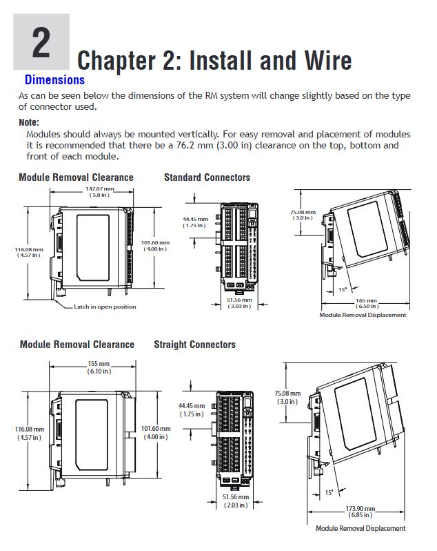
Appearance and installation: DIN rail installation (EN50022 standard), size 155mm × 116.08mm, weight 453.59g, requires vertical installation, with reserved 76.2mm maintenance space.
Power requirements: 20.4-30.8V AC/DC, Class 2 or SELV power supply, power consumption 4W/9VA, supporting Semi F47-0200 voltage drop standard.
Environmental adaptability: working temperature -18~65 ° C, storage temperature -40~85 ° C, 0-90% RH (non condensing), protection level IP20.
Certification standards: UL/EN 61010, Class 1 Div. 2 (optional), RoHS, WEEE, FM Class 3545 (limited version).
Warranty and Support: 3-year warranty (non misuse scenario), technical support can be obtained through phone, email or local representative, and RMA number needs to be applied for in advance for returns.
Core functions and technical features
1. Communication function
(1) Support agreement
Mainstream protocol: Modbus ® RTU/TCP、EtherNet/IP ™、 DeviceNet ™、 PROFIBUS DP, Some models include USB (Mini Type B) communication.
Basic communication: EIA-485/232 interface, Standard Bus (default), supports up to 247 Modbus nodes, maximum communication distance of 1200 meters.
(2) Communication parameters
Modbus: Address 1-247, baud rate 9600/19200/38400bps, supports Non/Even/Odd parity, configurable high and low byte order.
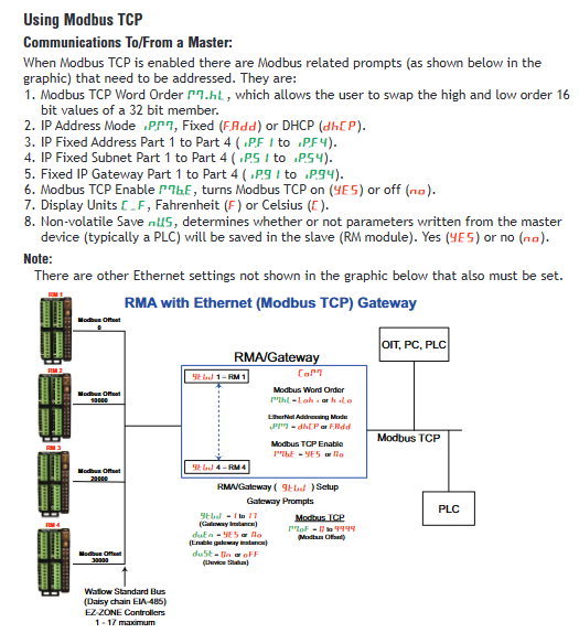
Ethernet: Supports DHCP/fixed IP, EtherNet/IP and Modbus TCP dual protocol enabled, with a maximum of 100 implicit communication members.
DeviceNet: Node address 0-63, baud rate 125/250/500kbps, supports Quick Connect for fast communication.
PROFIBUS DP: Address 0-126, supports DP-V0 (cyclic communication)/DP-V1 (non cyclic communication), maximum distance of 1200 meters.
2. Core extension functions
(1) Data Logging
Storage medium: Micro SD card (standard 2GB, supports larger capacity), CSV file format (can be opened directly with Excel).
Recording capability: up to 200 log points, with a recording period of 1-3600 seconds, supporting two full storage strategies: "stop" or "overwrite".
Trigger method: Recording can be started/stopped through signals such as digital input, alarm, timer, etc. The log contains a timestamp (dependent on real-time clock).
(2) Configure backup and recovery
Backup capacity: The basic version supports backup of 4 modules, while the enhanced version (SD card storage) supports full configuration backup of 16 modules.
Recovery mode: Manual recovery (Now), automatic recovery after module replacement (Change), supports cross module cloning configuration, reduces downtime.
Backup content: Module parameters (excluding User Set 1/2), excluding communication protocol assembly configuration.
(3) Real time clock (RTC)
Function: Provides date and time stamps (log/program linkage), supports program continuation after power interruption (Power Off Time parameter configuration).
Accuracy: ± 30ppm (25 ° C), battery backup (BR1225 lithium battery), typical battery life of 3 years after power failure.
(4) Security and Permissions
Password protection: Supports user/administrator two-level passwords, and can enable rolling passwords (automatically changed after power failure) to prevent unauthorized operations.
Hazardous area adaptation: Some models support Class 1 Div. 2 (Groups A-D), temperature code T4, and require the use of certified components.
Installation and Wiring Guide
1. Installation process
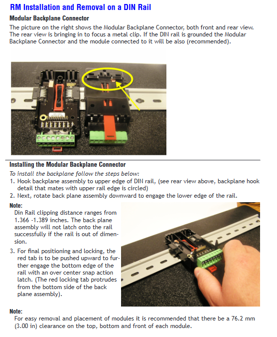
Rail installation: The hook is fixed to the 35mm rail and the rotating buckle is locked; Optional panel installation (customers need to provide their own fasteners).
Module networking: Multiple modules are horizontally spliced, sharing power and communication through the backplane bus, and supporting remote networking (up to 200 feet) using the "_stplit rail".
2. Wiring specifications
Terminal specifications: Supports 12-30 AWG wires, with a torque of 0.56 Nm (right angle terminal)/0.5 Nm (front terminal), and a stripping length of 7.6mm.
Core wiring:
Power supply: Slot C terminals 98 (+), 99 (-), need to distinguish AC/DC polarity.
Communication: Slot E (protocol terminal), Slot C (standard bus terminal CF/CD/CE), EIA-485 needs to distinguish T+/R+/T -/R -.
Bus wiring: Adopting a daisy chain topology, the first and last modules need to be connected to 120 Ω terminal resistors to avoid parallel wiring with power lines.
3. Typical networking methods
Single rail networking: RMA is directly connected to other RM modules through a backplane bus, sharing power and communication.
Track based networking: Connect two rails through Inter module Bus, provide single power supply across rails, and support remote module deployment.
Operation and Configuration Guide
1. Menu and Operation
Operation level: divided into three menus: Operations, Setup, and Factory, which can be configured through RUI (Remote User Interface) or software.
Core operation:
Address setting: Long press the panel button for 2 seconds to modify the Zone address (1-17), ensuring that the module address is unique.
Configuration method: Supports RUI local operation, EZ-ZONE Configurator/Composer software configuration (free download), Bluetooth (some models) remote configuration.
2. Key configuration items
(1) Communication configuration
Modbus: Set address, baud rate, parity, TCP mode requires configuring IP address (DHCP/fixed).
EtherNet/IP: Enable implicit/explicit communication and configure the number of assembly members (0-40).
DeviceNet: Set node address, baud rate, and enable Quick Connect.
(2) Data recording configuration
Log parameters: Set the recording period, full storage strategy, select up to 200 log points, support data sources such as analog inputs, alarms, process values, etc.
Format settings: Time format (HH: MM/HH: MM: SS), date format (MM/DD/YYYY/DD/MM/YYYY), configurable log precision (integer/decimal).
(3) Backup and Recovery Configuration
Backup operation: Setup → Backup → Save, select the backup range (single/multiple modules), and store the enhanced version to the SD card.
Recovery operation: Setup → Backup → Restore, supports manual triggering or module replacement for automatic recovery.
Maintenance and troubleshooting
1. Daily maintenance
Regular inspection: fastening of wiring terminals, SD card status, power stability, annual verification of communication links and log storage.
Cleaning and maintenance: Wipe the shell with a dry cloth to avoid corrosive cleaning agents, and regularly backup data for the SD card.
Battery replacement: After the real-time clock battery is depleted, the BR1225 model needs to be replaced by disconnecting the power supply.
2. Common faults and solutions
Possible causes and solutions for the fault phenomenon
Communication failure address/baud rate mismatch, wiring error, terminal resistance not connected. Check communication parameters, check EIA-485 polarity, and connect 120 Ω resistors at the beginning and end of the bus
Data recording failure: SD card not inserted/damaged, log points not configured. Replace SD card, reconfigure log point data source and cycle
Backup failed due to insufficient memory/SD card space, incompatible module model, cleaning storage media, confirming that the module belongs to the RM series and the address is unique
Power failure: voltage exceeds the range, power ripple is too large. Replace the compliant Class 2/SELV power supply and check the power supply circuit
Typical application scenarios
Multi protocol gateway: enables cross protocol communication between PLC and RM modules (such as EtherNet/IP to Modbus RTU).
Data collection and traceability: Record process parameters such as temperature and pressure, generate CSV logs for quality traceability.
System configuration backup: Batch backup of multiple module configurations for quick replacement of faulty modules and system recovery.
Distributed control networking: Through the track based networking function, remote module deployment and centralized monitoring can be achieved.
- YOKOGAWA
- Reliance
- ADVANCED
- SEW
- ProSoft
- WATLOW
- Kongsberg
- FANUC
- VSD
- DCS
- PLC
- man-machine
- Covid-19
- Energy and Gender
- Energy Access
- Renewable Integration
- Energy Subsidies
- Energy and Water
- Net zero emission
- Energy Security
- Critical Minerals
- A-B
- petroleum
- Mine scale
- Sewage treatment
- cement
- architecture
- Industrial information
- New energy
- Automobile market
- electricity
- Construction site
- HIMA
- ABB
- Rockwell
- Schneider Modicon
- Siemens
- xYCOM
- Yaskawa
- Woodward
- BOSCH Rexroth
- MOOG
- General Electric
- American NI
- Rolls-Royce
- CTI
- Honeywell
- EMERSON
- MAN
- GE
- TRICONEX
- Control Wave
- ALSTOM
- AMAT
- STUDER
- KONGSBERG
- MOTOROLA
- DANAHER MOTION
- Bentley
- Galil
- EATON
- MOLEX
- Triconex
- DEIF
- B&W
- ZYGO
- Aerotech
- DANFOSS
- KOLLMORGEN
- Beijer
- Endress+Hauser
- schneider
- Foxboro
- KB
- REXROTH
- YAMAHA
- Johnson
- Westinghouse
- WAGO
- TOSHIBA
- TEKTRONIX
- BENDER
- BMCM
- SMC
- HITACHI
- HIRSCHMANN
- XP POWER
- Baldor
- Meggitt
- SHINKAWA
- Other Brands
- UniOP
- KUKA
- IBA
- Beckhoff
-
ADLINK CPCI-6860A - 51-31310-OB10 industrial motherboard CompactPCI SBC
-
ADLINK AmITX-SL-G-H110 - 51-7A104-0A30 Mini-ITX Industrial Motherboard
-
ADLINK PXI-2005-003 - CPCI Industrial PC Data Acquisition Card Multi-Function DAQ
-
ADLINK DININ-814M - 51-14032-0A3D SCSI-100P cable connection Interface Terminal Board
-
ADLINK CPCI-3920NA/C2D15/M1G - 3U CompactPCI Intel Core 2 Duo Single Board Computer
-
ADLINK PCIE-8560 - 51-18014-0A20 Communication Card High Speed DAQ
-
ADLINK PCI-C154+ - Motion Control Card 4-axis Motion Controller Board
-
ADLINK PCI-RTV24 - image capture card Analog Video Frame Grabber
-
ADLINK NuPRO-842LV/P - 51-41360-0B30 Industrial Motherboard CPU Board
-
ADLINK cBP-3208/3208R - CPCI Board 3U 8-Slot CompactPCI Backplane
-
ADLINK PCI-8164 - 4-Axis Motion Controller PCI Card 51-12406-0A40
-
ADLINK PCIe-GIE64+ - 4-CH GigE Vision PoE+ Frame Grabber Video Capture Card
-
ADLINK CPCI-6860 / 6860A - CompactPCI Dual Xeon Single Board Computer
-
ADLINK IEC-915GV - REV 1.1 Industrial motherboard CPU Board
-
ADLINK ND-6520 - Technology RS-232 to RS-422RS-485 Converter NuDAM Module
-
ADLINK RTV-24 / PCI-MP4S - 51-12519-1C30 4-Channel Real Time Video Capture Board
-
ADLINK cPCI-6910 / cPCI-6910AM/M1G - cPCI-6910AM/DXL16/M1G/S80G(G)-3120 BOARD CompactPCI SBC
-
ADLINK NUPRO-A40H - Linghua 51-41807-1A30 Industrial Control Computer Motherboard
-
ADLINK USB-3488A - USB to GPIB INTERFACE USB-3488A(G) Controller Module
-
ADLINK PCI-8134A - motion control card 4-Axis Controller Card
-
ADLINK PCI-7432 - Board 32-Channel input / 32-output Isolated Digital I/O PCI Card
-
ADLINK PCI-8134A - 51-12421-0A10 motion controller card tested
-
ADLINK LPCIe-7230 - 32 CH Isolated Input/output Card 2 Interrupts Low Profile PCIe
-
ADLINK NuPRO-E340 - industrial computer motherboard 51-47807-0A30 PICMG 1.3 SHB
-
ADLINK PCI-7434 - High-speed Digital Acquisition Card 64-CH Isolated DO Card
-
ADLINK NuPRO-E330 - 51-41805-0A20 Indsutrial Board SHB Single Board Computer
-
ADLINK PCI-7248 - OPTO-22 48 CHANNEL DIO DIGITAL TTL/DTL I/O 51-12006-0A40 GP
-
ADLINK PCI-8134 - Motion control card 4-Axis Controller Card
-
ADLINK AMP-208C - Movimiento Control Tarjeta 51-12420-1A20 W/Expansión & Breakout
-
ADLINK PCI-8164 - 51-12406-0A40 PCB Board 4-Axis Motion Controller Card
-
ADLINK DIN-68Y-SGII / DIN-68M-J3A - Terminal Board Connector Interface Block
-
ADLINK PCIe-7432 - Technology 51-18402-0A10 PCIe Card With High Input Range
-
ADLINK PCI-8144 / PCI-8144N - Motion control card 4-Axis Stepper Controller Card
-
ADLINK HSL-HUB3/REPEATER - HIGH SPEED LINK EXTENSION MODULES Distributed Hub Module
-
ADLINK ND-6017 - Data Logging + Acquisition 8CH A/D input Mod NuDAM Module
-
ADLINK LPCIe-7250 - data acquisition card Low Profile 8-CH Relay Output Card
-
ADLINK PCI-7432 - I/O card 64-CH Isolated Digital Input Output PCI Card
-
ADLINK IMB-M43H - industrial control computer motherboard Q87 Chip Micro-ATX
-
ADLINK MP-C154 - Motion control Card 4-Axis Motion Controller Board
-
ADLINK PCI-RTV24 - image capture card Video Frame Grabber Card
-
ADLINK PCI-7250 - 8-CH Relay Output & 8-CH Isolated DI Card
-
ADLINK PCI-6308V - 8-CH 12-Bit Isolated Analog Output PCI Card PCB-I-E-1148=6EX2
-
ADLINK PCI-7248 - capture card 48-CH Opto-22 Compatible DIO Card
-
ADLINK HSL-AI16A02-M-VV - Analog Input Output Distributed Module
-
ADLINK NuPRO-A301 - Rev:1.4 NUPRO-A301 PICMG Full-Size Single Board Computer
-
ADLINK PCI-6208V-GL - 8-CH Voltage Analog Output PCI Card
-
ADLINK PCI-8134A - 51-12421-0A10 4-Axis Motion Controller Card
-
ADLINK MNET-S23 - TECHNOLOGY MNET S23 - SERVO DRIVER CONTROL MODULE
-
ADLINK M-342 - ATX I3 I5 I7 Q67 Industrial Motherboard
-
ADLINK NUPRO-780 - Industrial Motherboard CPU Board PICMG SBC
-
ADLINK MP-C154 / MP-C152 - 4-Axis Motion Control Card Pulse-Train Controller
-
ADLINK NuPRO-935A/LV10B0 - Motherboard 51-41802-0A10 GP w/RAM Industrial Control Board
-
ADLINK MP-C154 - Motion control card 4-Axis Motion Controller Mainboard
-
ADLINK PCI-7250 - PCI Acquisition Card 8-CH Relay Output Isolated DI Card
-
ADLINK ACL-7124 - Technology Inc.24 DIO Card Digital Input Output Card
-
ADLINK PCI-8554 A2 - Timer/Counter Data Acquisition Card
-
ADLINK DIN-825-GP4 - Terminal Block Interface Board Breakout Module
-
ADLINK NuPR0-761 - REV:1.1 Industrial motherboard Full-Size PICMG SBC
-
ADLINK MXE-1401/M8G (G) - Matrix Fanless Embedded Computer Industrial PC
-
ADLINK HSL-DI16DO16-UD-NN - Digital 16 Channel I/O Mod Distributed I/O Module
-
ADLINK ND6520 - NUDAM INTELLIGENT DA&C MODULE RS232-RS-422/RS485 CONVERTOR
-
ADLINK NUPRO-761 - REV:1.1 Industrial Motherboard CPU Board
-
ADLINK AMP-208C - Motion Control Card 51-12420-1A20 DSP-based 8-axis
-
ADLINK NuPRO-A301REV 1.4 - with packaging industrial computer motherboard PICMG SBC
-
ADLINK PCM-9112+ - 51-12300-0A2 industrial motherboard Multi-Function DAQ PC/104 Module
-
ADLINK PCM-7250+ - 8-CH Relay Outputs & 8-CH Isolated DI Module PC/104
-
ADLINK PCI-RTV24 - Image capture card Analog Video Frame Grabber
-
ADLINK PCI-8134 - Motion Controller PCI Card 4-Axis Controller Board
-
ADLINK PCI-7432 - Isolated Digital I/O PCI Card
-
ADLINK PCI-8554 A2 - acquisition card Timer/Counter Card
-
ADLINK PCI-8132 - Rev.A2 2-Axis Servo & Stepper Motion Controller Card
-
ADLINK PCI-8132 - Data Acquisition card 2-Axis Motion Controller Card
-
ADLINK EBP-13E4 - 51-46703-0A30 Industrial Backplane Board Passive Backplane
-
ADLINK PCI-800L - Electronic Card Interface Controller Card
-
ADLINK PCIe-GIE72 - 51-18531-0A10 PCB Board GigE Vision Frame Grabber
-
ADLINK DAQ-2010(G)-OOBO - Simultaneous-Sampling Multi-Function DAQ Card
-
ADLINK PCI-9112 - REV.B1 Multifunction DAQ Card Data Acquisition Card
-
ADLINK PCI-7230 - 51-12003-DA60 32-CH Isolated Digital I/O Card
-
ADLINK PCI-7432 - Data Acquisition Card Isolated Digital I/O PCI Card
-
ADLINK ETX-AT-N270-18/LXE - 51-71111-0A20 ETX CPU Module Motherboard
-
ADLINK HSL-DI32-UD-N - DIGITAL INPUT 32 POINTS MODULE Distributed I/O
-
ADLINK AMP-204C - Motion Control card DSP-Based 4-Axis Advanced Controller
-
ADLINK MNET-4XMOG-0050 - Four-axis Motion Controller Distributed Motion Module
-
ADLINK AMP-204C - Motion control card DSP-Based 4-Axis Pulse-Train Controller
-
ADLINK PCI-7442 - Switch card 64-Channel Datalogging & Acquisition Card
-
ADLINK M-302 - Industrial control motherboard ATX PC Board
-
ADLINK NUPRO-852 / NUPRO-852LV - Industrial motherboard Single Board Computer
-
ADLINK PCI-8134 - REV.B1. 4-Axis Motion Controller Card
-
ADLINK PCI-GIE62 + - 51-18502-0A20 2-CH GigE Vision Frame Grabber PoE Card
-
ADLINK PCI-MPG24 - 51-12523-0B20 MPEG4 Card Video Compression Hardware
-
ADLINK HSL-TB32-M-DIN - 32-CH I/O TERMINAL W/ HSL-AI16AO2-M-VV MODULE
-
ADLINK PCI-M114-GL - PCB Ver 2.1 Motion Controller Axis Card
-
ADLINK IMB-M40H - SYM76996H61 motherboard Industrial Computer Mainboard
-
ADLINK NUPRO-A40H - 51-41807-1A20 industrial control motherboard H61 Chip
-
ADLINK PCI-M114-GL - Axis Card Data Acquisition Card PCB VER2.2 Motion Controller
-
ADLINK PCI-8134 - Motion Controller PCI Card 4-Axis Controller Board
-
ADLINK PCI-8102 - Motion control card 2-Axis Servo & Stepper Controller
-
ADLINK NuPRO-841REV:3.0 - motherboard Industrial Control PC Board
-
ADLINK HSL-TB32-U-DIN REV A1 - Breakout Terminal Board Field I/O Module
-
ADLINK AMP-204C - Motion Control card DSP-Based 4-Axis Pulse-Train Controller
-
ADLINK NUPRO-A40H - 51-41807-1A20 industrial control motherboard H61 PC Board
-
ADLINK PCI-6308A / PCI-6308V - 51-12202-0A50 Isolated Analog Output Card
-
ADLINK AMP-204C - DSP-Based 4-Axis Advanced Pulse-Train Motion Controller
-
ADLINK PCI-7434 - Technology 64-Channel Isolated Digital I/O PCI Cards
-
ADLINK CPCI-6840 / CPCI-6840V / PM16/M1G-12G0 - CompactPCI Single Board Computer CPU Module
-
ADLINK PCIE-GIE74 - Motherboard Video Capture Card 51-18531-0A10 Frame Grabber
-
ADLINK NuPRO-E330 - industrial computer equipment motherboard Control Mainboard
-
ADLINK AMP-208C / 51-12420-1A20 - Motion Control Card W/ Expansion & Breakout Board
-
ADLINK HPCI-14S12U - industrial computer baseboard Passive Backplane 14 Slots
-
ADLINK PCI-8164 - 4-Axis Motion Controller PCI Card W/ 1x Cable, 1x Breakout Box
-
ADLINK PCIe-RTV24 - 51-18016-0A20 Image Acquisition Video Capture Card
-
ADLINK M-342 - 5 PCI ATX Motherboard Industrial PC Mainboard
-
ADLINK PCI-FIW64 - 4/2 Channel IEEE1394B Image Capture Card FireWire Frame Grabber
-
ADLINK PCI-7432 - digital IO card 64-CH Isolated Digital Input Output Card
-
ADLINK 51-12001-0C20 - Circuit Board PCI-7200 Data Acquisition Controller Card
-
ADLINK PXI-3920 - PXI 3U cPCI Industrial Controller Embedded System CPU Board
-
ADLINK NuPRO-841REV:2.0 - motherboard Industrial Control PC Board
-
ADLINK NuPro-E330 - 51-41805-0A20 PCB Industrial Control Computer Motherboard
-
ADLINK PCI-RTV24 - Image capture card Analog Video Frame Grabber
-
ADLINK PCI-7442 - Switch card 64-Channel Datalogging & Acquisition Card
-
ADLINK HPX-13S4 - device baseboard Passive Backplane Riser Card
-
ADLINK PCI-9112 REV A.1 - Multi Function DA&C Board Data Acquisition Card
-
ADLINK PCI-7248 - 51-12006-0A40 Card Control 48-CH Digital I/O Module
-
ADLINK CPCI-6860 / 6860A - motherboard CompactPCI Dual Xeon Single Board Computer
-
ADLINK DPAC-3020-11(G) - Embedded PC Automation Controller Machine Control Board
-
ADLINK NuPRO-841 REV:1.0 - industrial control motherboard CPU Board
-
ADLINK MNET-4XMOG-0050 - Four-axis Motion Controller MNET Motion Control Card
-
ADLINK ETX-AT-N270-18/LXE - 51-71111-0A20 ETX CPU Module Motherboard

K-JIANG

Add: Jimei North Road, Jimei District, Xiamen, Fujian, China
Tell:+86-15305925923