
K-WANG


Eaton A200/A210/A250 Specification 5 Motor Controller Operating Manual
Eaton A200/A210/A250 Specification 5 Motor Controller Operating Manual
Product positioning
The operating manual for Eaton A200/A210/A250 5 motor controller (document number IL17054, effective May 2011, replacing the old version from June 1998) is positioned as an industrial grade full voltage starting motor controller, supporting irreversible or reversible control and providing motor overload protection (relying on overload relays and heaters), but does not have short-circuit protection function and needs to be used in conjunction with external short-circuit protection devices (such as fuses and circuit breakers). The product is suitable for driving and controlling three-phase motors in industrial scenarios, and only professional personnel who have received sufficient training are allowed to install, operate, and maintain it. Local and national electrical regulations and safety standards must be followed.
Core Technical Parameters
Category specific parameters
Pole configuration: 2-pole (current rating is the same as 3-pole, does not support three-phase motors), 3-pole (supports three-phase motors)
Voltage and power (60Hz) 200V: 75HP; 230V:100HP; 460/575V:200HP
Current specifications: open circuit starter: 300A; closed starter: 270A
Short circuit withstand current according to SCPD type: 65000A (Class J/K/R/T fuse), 100000A (HMCP model), 200000A (LA+TRI-PAC model)
The cable requires copper conductor, wire gauge 2/0 AWG-500 MCM, and is compatible with a current carrying capacity of 75 ℃
Working environment: Industrial environment, suitable for conventional temperature and humidity (no specific values, must comply with general electrical equipment standards)
Detailed explanation of core components and functions
Overload protection system
Component type, key characteristics, specification parameters
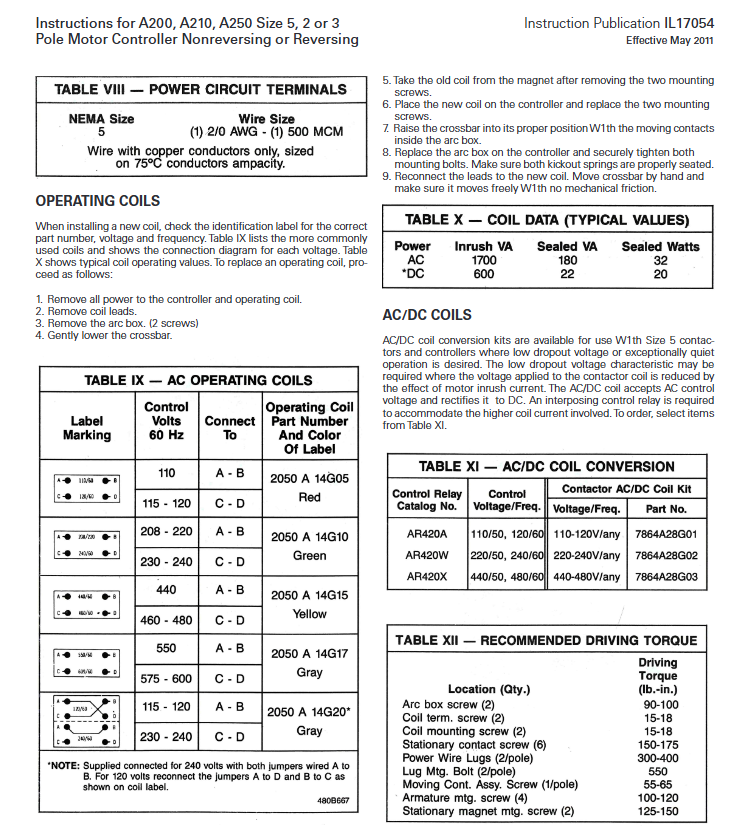
Type A overload relay is divided into temperature compensation (gray reset lever, marked as "ambient compensated") and non compensation (red reset lever, not marked); Support manual/automatic reset; With ± 15% setting adjustment; Normally closed control contact control circuit contact rating: AC 120-600V, connect 30A/3600VA, disconnect 3A/360VA
B-type overload relay is divided into temperature compensation (gray reset lever) and non compensation (red reset lever); When triggered, the yellow indicator pops up and hides after resetting; Normally closed control contact, optional normally open contact control circuit contact rating: AC 120-600V, connect 20A/2400VA, disconnect 2A/240VA
The heater needs to be ordered separately and selected based on the rated current of the motor and the service factor; The tripping current at 40 ℃ is 125% of the minimum rated current of the motor; Under 600% tripping current, the tripping adaptation current range is 100-300A within 20 seconds, corresponding to models FH23-FH34
Core Accessories and Functions
Operating coil: AC voltage adaptation (120V/240V/460-480V, etc.), some models support AC/DC conversion (requires matching control relays); The maximum suction power is 1700VA, and the holding power is 20-32VA; when replacing, the model, voltage, and frequency need to be checked.
Arc hood: Built in De ion ® Arc extinguishing barrier, providing mechanical limit and arc extinguishing functions for contacts; Must be securely installed, otherwise operation is prohibited; Regularly check whether the grid is damaged due to malfunction.
J-shaped auxiliary contacts: up to 2 units can be installed, providing up to 4 auxiliary circuits; Supports configurations such as 2 normally closed, 1 normally open, and 1 normally closed (delayed disconnection); During installation, adjust the operating arm to ensure that the push rod can be pressed an additional 1/16 inch when the controller is fully closed.
GCO current transformer: 300/5 ratio, black casing with nameplate; The primary winding is implemented by a load connection strip, and the secondary winding (black and white wires) is connected to an overload relay; Prohibit secondary winding open circuit (to avoid overvoltage damage); Install a maximum of 3 and a minimum of 2 (on both sides).
Mechanical interlocking: Suitable for multi controller combination installation to prevent simultaneous closure; Vertical installation uses M47/M49 type, horizontal installation uses M48/M50 type.
Installation and wiring specifications
Installation Requirements
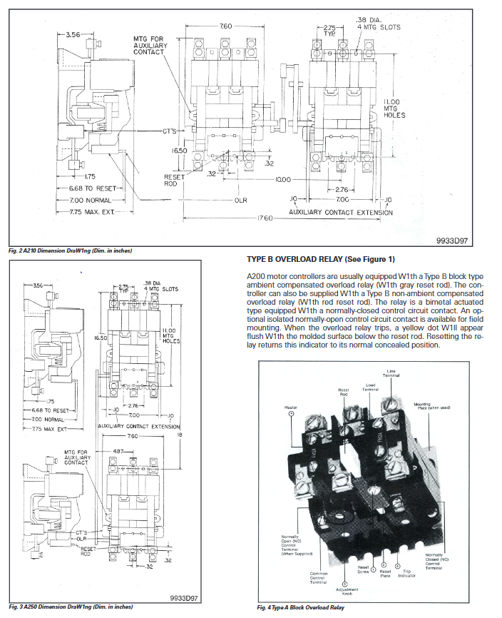
Installation posture: Vertical installation, with the incoming terminal located above the load terminal; The overload relay needs to be installed vertically with the reset rod facing downwards.
Fixed requirement: Tighten with designated bolts, with the following torque for key parts:
Component torque range (pounds inches)
Arc cover screws 15-18
Fixed contact bolt 150-175
Terminal bolt 55-65
Screw 125-150 for moving contact assembly
Environmental requirements: Avoid harsh environments such as dust and humidity, and ensure that the mechanism operates without any jamming.
Wiring specifications
Main circuit wiring: Inlet/outlet terminal aperture 17/32 inches, compatible with 1/2 inch hardware; The pressure type terminal is installed on the inlet side behind the copper terminal strip, and the load side is installed on the front side.
Control circuit wiring: The normally closed contacts of the overload relay are connected in series in the control circuit, and the coil power is cut off when triggered; Auxiliary contacts are wired according to control logic (such as self-locking and interlocking).
Transformer wiring: The black and white wires of the GCO secondary winding are connected to the corresponding terminals of the overload relay, and the same group of wires should be connected to the same overload relay pole; When wiring, avoid cables obstructing the movement of the crossbar.
Maintenance and replacement of accessories
Key points of daily maintenance
Contact inspection: The new contact overtravel is 13/64-17/64 inches. When worn to 1/16 inch, all poles need to be replaced simultaneously; Measure the contact pressure (initial 6-7 pounds, final 7.5-8.5 pounds), if the pressure is insufficient, replace the contact or spring.
Institutional inspection: The horizontal bar and spring move flexibly without any jamming; Electrical and mechanical interlocking installation and adjustment in place; The arc cover is undamaged and the arc extinguishing grid is intact.
Overload relay inspection: Regularly test the reset function, and confirm the environmental adaptability for temperature compensation type; The heater is firmly connected and the surface is clean without oxidation.
Key component replacement process
Operation coil replacement: Power off → Remove coil leads → Remove arc cover → Lower crossbar → Remove old coil fixing screws → Install new coil → Reset crossbar and arc cover → Reconnect wires → Manually test crossbar movement flexibility.
Contact replacement: Power off → Remove the arc cover → Lower the crossbar → Remove the moving contact assembly → Replace the moving and stationary contacts → Reset the spring and assembly → Tighten the fixing bolts (150-175 pound inches) → Install the arc cover.
Overload relay replacement: Power off → Remove wiring → Use 7/16 inch 8-32 screws to remove old relay → Install new relay (reset lever facing down) → Reconnect wiring → Test trigger and reset function.
Critical Safety and Taboos
Only trained personnel are allowed to operate. Before installation and maintenance, power must be turned off and no voltage must be confirmed;
Do not operate without an arc cover, otherwise it may cause arc danger;
GCO current transformer secondary winding must never be open circuited to avoid overvoltage damage to equipment;
2-pole controller cannot be used for three-phase motor control;
The automatic reset function cannot be used for 2-wire control circuits (to avoid accidental motor start-up);
When the heater burns out, the complete overload relay needs to be replaced, and the heater cannot be replaced separately.
- YOKOGAWA
- Reliance
- ADVANCED
- SEW
- ProSoft
- WATLOW
- Kongsberg
- FANUC
- VSD
- DCS
- PLC
- man-machine
- Covid-19
- Energy and Gender
- Energy Access
- Renewable Integration
- Energy Subsidies
- Energy and Water
- Net zero emission
- Energy Security
- Critical Minerals
- A-B
- petroleum
- Mine scale
- Sewage treatment
- cement
- architecture
- Industrial information
- New energy
- Automobile market
- electricity
- Construction site
- HIMA
- ABB
- Rockwell
- Schneider Modicon
- Siemens
- xYCOM
- Yaskawa
- Woodward
- BOSCH Rexroth
- MOOG
- General Electric
- American NI
- Rolls-Royce
- CTI
- Honeywell
- EMERSON
- MAN
- GE
- TRICONEX
- Control Wave
- ALSTOM
- AMAT
- STUDER
- KONGSBERG
- MOTOROLA
- DANAHER MOTION
- Bentley
- Galil
- EATON
- MOLEX
- Triconex
- DEIF
- B&W
- ZYGO
- Aerotech
- DANFOSS
- KOLLMORGEN
- Beijer
- Endress+Hauser
- schneider
- Foxboro
- KB
- REXROTH
- YAMAHA
- Johnson
- Westinghouse
- WAGO
- TOSHIBA
- TEKTRONIX
- BENDER
- BMCM
- SMC
- HITACHI
- HIRSCHMANN
- XP POWER
- Baldor
- Meggitt
- SHINKAWA
- Other Brands
- UniOP
- KUKA
- IBA
- Beckhoff
- ADLINK
-
Beckhoff CX1100-0910 - Power Supply Module
-
Beckhoff C5210-0010 - Communication Module C5210
-
BECKHOFF KL1352 - Bus Terminal SET OF 2 FREE FAST SHIP
-
Beckhoff EL3058 - 8 x analog input single ended 4...20mA 85惟 shunt 12bit
-
Beckoff CX1100-0920 - UPS Module 24VDC (US SELLER) * *
-
BECKHOFF C6920-0000 - C69200000 PLC Moudule
-
Beckhoff CX5120-0115 - CPU controller module CX5120-0115
-
Unknown 15F5C1E-Y50A - Of Frequency Converters
-
Beckhoff AX5118-0000-0200 - Servo Drive HTP0
-
BECKHOFF AX5106-0000-0200 - Servo Drive
-
Beckhoff CX5240-0175 - Module (free) #U2327D YG
-
Beckhoff CP6607-0001-0000 - Compact PC Panel Economy Installation Operator 5,7 "
-
Beckhoff EP3744-0041 - 2022 EP37440041 Module
-
Beckhoff CP6209-0001-0020 - 6.5" PC Touch Screen Control Panel 24VDC
-
Beckhoff CX9020-0111 - /U900 +8x+2xEL3121+1x EL9410+3xEL1008+1x EL2008 Set
-
Beckhoff C6525-1030-0050 - Industrial PC
-
Beckoff CX1100-0920 - UPS Module 24VDC (US SELLER)
-
Beckhoff CX5010-0120 - CX5010 Processor Intel Atom Z510 B24
-
Siemens 6FC5203-0AF04-1BA1 - Operation Panel
-
Beckhoff CX5230-0175 - / 000029724 Embedded PC / Industrial PC on Rail
-
Beckhoff CP3916-0000 - industrielles Anzeige- und Bedienterminal
-
BECKHOFF CX1500-M310 - CX1000-N000 CX1000-0011 CX1000-C00L CX1100-0002 PLC Module
-
Beckhoff EL1872 - 16-channel digital input terminal
-
BECKHOFF EP2318-0001 - module
-
Beckhoff CX9020-0110 - Basic CPU Module
-
Beckhoff EL2564 - EtherCAT Terminal, 4-channel LED output, 5鈥?8VDC, 4A, RGBW
-
Beckhoff CX5130-0155 - /000105637 Automation Embedded PC
-
B&R 400 - Power Control Panel Rev D0 24 VDC
-
Beckhoff CX2020-0155 - module
-
Beckhoff CX9020-0115 - PLC Module
-
BECKHOFF EL6695 - PLC EL 6695
-
BECKHOFF EL7047 - PLC Modules
-
Beckhoff CX1000-0012 - Control HW 2.2 + CX1500-M310 + CX1000-C00L + CX1100-0002+
-
Beckhoff C6920-1039-0030 - control cabinet industrial PC CPU Celeron 1.90 GHz, 2 cores
-
BECKHOFF CX1100-0910 - PLC Module#
-
Beckhoff IL2301-B318-0000 - Coupler Box 4 Channel Digital Input |
-
Beckhoff CX7080 - Module
-
Beckhoff C6930-0060 - Industrial PC
-
Beckhoff CP7902-1060-0000 - Touchscreen 15 " CP7902
-
beckhoff CX9020-0111 - Controller module or UPS
-
Beckhoff CX8091 - PLC Module CX8091
-
Beckhoff C6640-1008-0030 - Control Cabinet Industrial PC
-
BECKHOFF CX1100-0920 - module
-
Beckhoff C9900-M921 - see pictures
-
BECKHOFF CP6829-0001-0000 - Touch Panel
-
BECKHOFF C6930-0060 - Industrial Computer
-
BECKHOFF CX8050 - PLC module
-
Beckhoff CP6202-0021-0020 - Touch Screen #
-
BECKHOFF AM3031-0C20-0000 - SERVO MOTOR
-
Unknown BCH1302N11A1C - Servo motor
-
Beckhoff EL2502 - 2-channel pulse width output terminal
-
Beckhoff EL6731 - Profibus Master / *Rev: 0025
-
Beckhoff CP3918-0010 - Control Panel
-
BECKHOFF CP2915-0010 - [24 MONTH WARRANTY] Control Panel
-
Beckhoff AX5203-0000-0202 - Servo Drive
-
Schneider TSXDSY64T2K - PLC OUTPUT MODULE
-
Beckhoff EP4174-0002 - Module-
-
Beckhoff IL2302-B318-0000 - Profibus Box
-
Beckhoff CP6709-0001-0000 - Touchpanel
-
BECKHOFF CX2030-0123 - Controller
-
Beckhoff CX9020-0111 - Processor Module
-
Beckhoff CX1020-0000 - CX Basic CPU Module
-
Beckhoff AX2003-AS - Servo Drive HTP0
-
Beckhoff C6240-1052-0040 - 4-086-06-3073 Industrial Computer CB1052-0003
-
Beckhoff EL1918 - 8 xTwinSAFE Input
-
Beckhoff AM8072-0R20-0000 - Servomotor
-
BECKHOFF AM8021-1B21-0000 - servo motor #T882 YS
-
Beckhoff EL6224 - 4 X Terminal IO-LINK
-
Beckhoff CX5140-0135 - embedded PC with Intel Atom processor 4 GB HW 3.6
-
Beckhoff CP7201-1000-0000 - Panel PC #
-
Beckhoff CX5130-0121 - Embedded-PC 4GB CPU Module HW 2.5 Industrial PC
-
Beckhoff AM8022-0D41-1002 - Servomotor
-
BECKHOFF CX2030-0130 - Module
-
BECKHOFF EL1872 - 16-channel digital input terminal
-
Unknown GXMMW.A203P33 - 1pc encoder
-
Beckhoff EL6631-0000 - EtherCAT Terminal 2-Port EL 6631
-
BECKHOFF C6925-0030 - Industrial Computer
-
Beckhoff CX8190 - A Module
-
BECKHOFF CX2040-0135 - CX2040-0135/000000927 CPU BASE MODULE i7 2715QE 2.1GHz --
-
BECKHOFF KL6023-0000 - Wireless adapter
-
Saia Burgess PCD7.F700 - PCD7F700 Communication Module
-
Beckhoff CX5130-0112 - CPU Module
-
BECKHOFF CX1020-N010 - CX1020-N000 CX1020-0111 CX1100-0004 EL2008 EL3064 EL4004
-
Beckhoff EP1819-0021 - A Module
-
Beckhoff CX2030-0120 - / 4gb with CX2100 0004
-
B&R X20-XC-0292 - Automation Powerlink Ethernet Bus Controller Module
-
Beckhoff BK3110 - One PLC Module
-
BECKHOFF KL3222 - PLC Module
-
BECKHOFF CX1500-M310 - CX1000-N000 CX1000-0011 CX1000-C00L CX1100-0002 PLC MODULE
-
Beckhoff CP3918-0010 - Control Panel
-
Beckhoff CX2030-0100-1002 - /4GB + CX2100 + CX2550 + CX2500-0060 + SSD
-
Beckhoff EP1816-0008 - PLC Module
-
Beckhoff CX5130-0112 - Module
-
Beckhoff Cx1500-m750 - CPU Hw: 1.4
-
BECKHOFF AX5112-0000-0200 - AX511200000200 Servo Driver
-
Beckhoff EL3751 - EtherCAT Terminal 1 Channel Analog Input Multifunction 24 Bit
-
Beckhoff CX1100-0002 - Power Supply Module
-
Beckhoff CP3916-1016-0010 - Control Panel
-
BECKHOFF CX9001-1101 - #NAME?
-
Beckhoff EP3174-0002 - EtherCAT Box Module
-
Beckhoff C6030-0070 - servo drive
-
Beckhoff CX2020-0120 - /4GB CPU, CX2100-0904, 3x EL6900, EL1904, 16GB Memory
-
BECKHOFF C6110 - BOX-PC 113608
-
BECKHOFF EK1914 - module #P
-
Beckhoff C6140 - Ipox IP-4GVI63 + CH7009A_DVI_TV + SIEMENS A5E00369843 + WD800AAJB
-
Beckhoff CX5020-0111 - controller Good quality
-
BECKHOFF C6015-0010 - / 6559380 ULTRA-COMPACT INDUSTRIAL PC ()
-
Beckhoff AX5203-0000-0200 - PLC module
-
Beckhoff EL2872 - 16-channel digital output terminal
-
BECKHOFF C3640-0000 - Panel Industrial PC 100/240VAC 128MB E0122L
-
Beckhoff CX8031 - Module
-
Beckhoff CX5020-0120-1002 - PLC module#
-
Beckhoff C6140 - M845B + SIEMENS A5E00369843 + C9900_A159_1 + AUTOMATA CAN PCI 1N
-
BECKHOFF AX5112-0000-0200 - Servo Drive*ie
-
B&R ECPA42-01 - Analog Output Module 4-Channel, +/- 10V Output Signal, 20mA Max
-
Beckhoff EL6631-0010 - PLC Module
-
BECKHOFF C6930-0070 - CONTROL CABINET INDUSTRIAL PC
-
BECKHOFF AX5112-0000-0200 - AX511200000200 Servo Driver
-
BECKHOFF EK9000 - Programmable Logic Controller Module EK9000 EK9000
-
BECKHOFF C6920-1028-0000 - Industrial computer
-
Beckhoff CX2030-0120 - controller Module
-
Beckhoff BX8000-0000 - Bus Terminal Controller HW 4.4
-
B&R 3NC154.60-2 - Positioning Module#
-
BECKHOFF CX1020-0122 - PLC module
-
Beckhoff AM3032-0D40-0000 - Servo Motor
-
BECKHOFF CX5020-0111 - CPU Module CX5020-0111
-
Beckhoff CB1051 - G5 Motherboard
-
BECKHOFF KL2641 - 1-channel relay output terminal

K-JIANG

Add: Jimei North Road, Jimei District, Xiamen, Fujian, China
Tell:+86-15305925923