
K-WANG


KUKA KR C2 edition2005 Robot Controller Operation Manual
KUKA KR C2 edition2005 Robot Controller Operation Manual
The KUKA KR C2 edition 2005 Robot Controller Operation Manual covers core content such as product description, technical data, safety specifications, planning, transportation, startup and debugging, operation, maintenance, repair, troubleshooting, and KUKA services. It clarifies that the target users of the controller are personnel with advanced knowledge of electrical and electronic systems, robot controllers, and Windows systems. The core function is to operate KUKA industrial robots, linear units, and locators, emphasizing the need to strictly follow safety specifications and operating procedures to avoid personal injury and equipment damage. At the same time, it provides detailed component information, operating steps, and fault handling solutions.
Product Core Information
composition structure
Industrial robot: composed of manipulator (mechanical arm and electrical device), robot controller, teaching pendant (KCP), connecting cable, software, and optional accessories
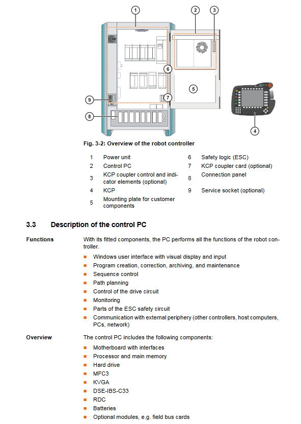
Robot controller: including control PC, power unit, KCP, ESC safety logic, KCP coupler (optional), service interface (optional), connection panel
Key component description
Control PC: The core functions include program creation, path planning, driver control, etc., including motherboard, hard disk, MFC3, KVGA and other components, supporting multiple interfaces (USB, Ethernet, serial port, etc.)
Power supply unit: including KPS600 power supply, KPS-27 low-voltage power supply, KSD servo driver, fuse, fan, etc., providing 24V and other voltage outputs
ESC safety logic: dual circuit computer safety system, monitoring emergency stop, enabling devices, etc., including CI3 series cards (Standard/Extended/Bus/Tech)
KCP (Teaching pendant): including mode selection switch, emergency stop button, enable switch, etc., protection level IP54 (top)/IP23 (bottom), weight 1.4kg
Technical data
Category key parameters
Maximum number of axes for basic parameters: 8 axes; Protection level: IP54; Average sound level: 67 dB (A)
Power supply requirements rated voltage: AC 3x400V-3x415V (tolerance ± 10%); Frequency: 49-61Hz; Rated power: Standard 7.3kVA, Heavy load 13.5kVA
Environmental operating temperature:+5~+45 ℃ (without cooling unit)/+5~+55 ℃ (with cooling unit); Storage temperature: -25~+70 ℃ (without battery); Humidity: 3k3 level (no condensation)
Size and gap installation gap: The minimum gap requirement must be followed (see document diagram for details); Cabinet door opening angle: about 180 ° for independent cabinets and about 155 ° for parallel cabinets
Cable length: Motor cable: standard 7m, optional 15/25/35/50m; KCP cable: standard 10m, expandable up to 60m
Safety regulations
core principle
Only allowed for intended use (such as operating KUKA industrial robots), and misuse of personnel/animal transportation, climbing, and hyperparameter operation is prohibited
Compliance with standards such as the EC Machinery Directive (2006/42/EC) and the EMC Directive (2004/108/EC) is required
Personnel Requirements
Operators need to have advanced knowledge of electrical and electronic systems, robot controllers, and Windows systems. It is recommended to attend KUKA College training
The system integrator is responsible for installation, risk assessment, and compliance declaration; Maintenance needs to be carried out by professionally trained personnel
Key safety functions
Operation modes: T1 (manual low speed ≤ 250mm/s), T2 (manual high speed), AUT (automatic), AUT EXT (external automatic)
Safety devices: local/external emergency stop button, dual circuit enable switch, safety door interlock, software limit switch, mechanical terminal block
Stop category: STOP 0 (immediate stop), STOP 1 (path keeping stop), STOP 2 (normal deceleration stop)
Scene security measures
Transportation: The controller needs to be transported upright to avoid vibration and impact; The manipulator needs to be placed in the designated transportation location according to regulations
Startup: Wiring, safety devices, and temperature adaptation need to be checked. The new program needs to be tested in T1 mode first
Maintenance/Repair: Power off and lock, post warning labels, wait for 5 minutes to discharge after power off (some components have residual voltage of 50-600V)
Operation and maintenance
Startup and Debugging
Core steps: Install controller → Connect cables → Connect KCP → Equipotential connection → Connect power supply → Configure X11 interface → Power on → Check fan direction → Safety equipment testing → Software configuration
Key requirements: Ensure no condensation, correct wiring, and avoid errors caused by cable swapping
routine operations
KCP coupler: supports connection/disconnection during operation, which needs to be operated by pressing the request button. After disconnection, KCP needs to be removed to avoid misuse
Startup method: Supports booting from KUKA USB stick, press F10 to select the startup option
Maintenance cycle and tasks
| Maintenance cycle | Task content |
| Maximum 2 years | Clean internal and external fans, heat exchangers, and heat sinks; Check the tightness of the components |
| 2 years | Replace the battery |
| 5 years | Replace the motherboard battery; 3 shift operation requires replacement of PC fan |
| 5 years | replacement of internal and external fans |
| replacement of filter element when color changes | replacement of pressure relief plug filter element|
Maintenance and troubleshooting
Common maintenance tasks
Component replacement: Supports the replacement of control PCs, fans, motherboards, memory, hard drives, CI3 boards, RDC/SafeRDC boards, batteries, etc., and must comply with ESD specifications
Software installation: KUKA System Software (KSS) can be reinstalled
fault diagnosis
Tools: DSE-RDW diagnostic tool (monitoring DSE-RDC communication, drive bus), ESC diagnostic tool (monitoring safety circuit)
Common errors: Control PC startup failure, MFC3 initialization failure, bus communication error, KCP no display, etc. Provide error causes and solutions
Error code: Meaning and handling plan of error codes containing KPS600, KSD and other components (e.g. Pr1 Trip is a checksum error for parameter set 1)
- YOKOGAWA
- Reliance
- ADVANCED
- SEW
- ProSoft
- WATLOW
- Kongsberg
- FANUC
- VSD
- DCS
- PLC
- man-machine
- Covid-19
- Energy and Gender
- Energy Access
- Renewable Integration
- Energy Subsidies
- Energy and Water
- Net zero emission
- Energy Security
- Critical Minerals
- A-B
- petroleum
- Mine scale
- Sewage treatment
- cement
- architecture
- Industrial information
- New energy
- Automobile market
- electricity
- Construction site
- HIMA
- ABB
- Rockwell
- Schneider Modicon
- Siemens
- xYCOM
- Yaskawa
- Woodward
- BOSCH Rexroth
- MOOG
- General Electric
- American NI
- Rolls-Royce
- CTI
- Honeywell
- EMERSON
- MAN
- GE
- TRICONEX
- Control Wave
- ALSTOM
- AMAT
- STUDER
- KONGSBERG
- MOTOROLA
- DANAHER MOTION
- Bentley
- Galil
- EATON
- MOLEX
- Triconex
- DEIF
- B&W
- ZYGO
- Aerotech
- DANFOSS
- KOLLMORGEN
- Beijer
- Endress+Hauser
- schneider
- Foxboro
- KB
- REXROTH
- YAMAHA
- Johnson
- Westinghouse
- WAGO
- TOSHIBA
- TEKTRONIX
- BENDER
- BMCM
- SMC
- HITACHI
- HIRSCHMANN
- XP POWER
- Baldor
- Meggitt
- SHINKAWA
- Other Brands
- UniOP
- KUKA
- IBA
- Beckhoff
- ADLINK
-
Beckhoff CX1100-0910 - Power Supply Module
-
Beckhoff C5210-0010 - Communication Module C5210
-
BECKHOFF KL1352 - Bus Terminal SET OF 2 FREE FAST SHIP
-
Beckhoff EL3058 - 8 x analog input single ended 4...20mA 85惟 shunt 12bit
-
Beckoff CX1100-0920 - UPS Module 24VDC (US SELLER) * *
-
BECKHOFF C6920-0000 - C69200000 PLC Moudule
-
Beckhoff CX5120-0115 - CPU controller module CX5120-0115
-
Unknown 15F5C1E-Y50A - Of Frequency Converters
-
Beckhoff AX5118-0000-0200 - Servo Drive HTP0
-
BECKHOFF AX5106-0000-0200 - Servo Drive
-
Beckhoff CX5240-0175 - Module (free) #U2327D YG
-
Beckhoff CP6607-0001-0000 - Compact PC Panel Economy Installation Operator 5,7 "
-
Beckhoff EP3744-0041 - 2022 EP37440041 Module
-
Beckhoff CP6209-0001-0020 - 6.5" PC Touch Screen Control Panel 24VDC
-
Beckhoff CX9020-0111 - /U900 +8x+2xEL3121+1x EL9410+3xEL1008+1x EL2008 Set
-
Beckhoff C6525-1030-0050 - Industrial PC
-
Beckoff CX1100-0920 - UPS Module 24VDC (US SELLER)
-
Beckhoff CX5010-0120 - CX5010 Processor Intel Atom Z510 B24
-
Siemens 6FC5203-0AF04-1BA1 - Operation Panel
-
Beckhoff CX5230-0175 - / 000029724 Embedded PC / Industrial PC on Rail
-
Beckhoff CP3916-0000 - industrielles Anzeige- und Bedienterminal
-
BECKHOFF CX1500-M310 - CX1000-N000 CX1000-0011 CX1000-C00L CX1100-0002 PLC Module
-
Beckhoff EL1872 - 16-channel digital input terminal
-
BECKHOFF EP2318-0001 - module
-
Beckhoff CX9020-0110 - Basic CPU Module
-
Beckhoff EL2564 - EtherCAT Terminal, 4-channel LED output, 5鈥?8VDC, 4A, RGBW
-
Beckhoff CX5130-0155 - /000105637 Automation Embedded PC
-
B&R 400 - Power Control Panel Rev D0 24 VDC
-
Beckhoff CX2020-0155 - module
-
Beckhoff CX9020-0115 - PLC Module
-
BECKHOFF EL6695 - PLC EL 6695
-
BECKHOFF EL7047 - PLC Modules
-
Beckhoff CX1000-0012 - Control HW 2.2 + CX1500-M310 + CX1000-C00L + CX1100-0002+
-
Beckhoff C6920-1039-0030 - control cabinet industrial PC CPU Celeron 1.90 GHz, 2 cores
-
BECKHOFF CX1100-0910 - PLC Module#
-
Beckhoff IL2301-B318-0000 - Coupler Box 4 Channel Digital Input |
-
Beckhoff CX7080 - Module
-
Beckhoff C6930-0060 - Industrial PC
-
Beckhoff CP7902-1060-0000 - Touchscreen 15 " CP7902
-
beckhoff CX9020-0111 - Controller module or UPS
-
Beckhoff CX8091 - PLC Module CX8091
-
Beckhoff C6640-1008-0030 - Control Cabinet Industrial PC
-
BECKHOFF CX1100-0920 - module
-
Beckhoff C9900-M921 - see pictures
-
BECKHOFF CP6829-0001-0000 - Touch Panel
-
BECKHOFF C6930-0060 - Industrial Computer
-
BECKHOFF CX8050 - PLC module
-
Beckhoff CP6202-0021-0020 - Touch Screen #
-
BECKHOFF AM3031-0C20-0000 - SERVO MOTOR
-
Unknown BCH1302N11A1C - Servo motor
-
Beckhoff EL2502 - 2-channel pulse width output terminal
-
Beckhoff EL6731 - Profibus Master / *Rev: 0025
-
Beckhoff CP3918-0010 - Control Panel
-
BECKHOFF CP2915-0010 - [24 MONTH WARRANTY] Control Panel
-
Beckhoff AX5203-0000-0202 - Servo Drive
-
Schneider TSXDSY64T2K - PLC OUTPUT MODULE
-
Beckhoff EP4174-0002 - Module-
-
Beckhoff IL2302-B318-0000 - Profibus Box
-
Beckhoff CP6709-0001-0000 - Touchpanel
-
BECKHOFF CX2030-0123 - Controller
-
Beckhoff CX9020-0111 - Processor Module
-
Beckhoff CX1020-0000 - CX Basic CPU Module
-
Beckhoff AX2003-AS - Servo Drive HTP0
-
Beckhoff C6240-1052-0040 - 4-086-06-3073 Industrial Computer CB1052-0003
-
Beckhoff EL1918 - 8 xTwinSAFE Input
-
Beckhoff AM8072-0R20-0000 - Servomotor
-
BECKHOFF AM8021-1B21-0000 - servo motor #T882 YS
-
Beckhoff EL6224 - 4 X Terminal IO-LINK
-
Beckhoff CX5140-0135 - embedded PC with Intel Atom processor 4 GB HW 3.6
-
Beckhoff CP7201-1000-0000 - Panel PC #
-
Beckhoff CX5130-0121 - Embedded-PC 4GB CPU Module HW 2.5 Industrial PC
-
Beckhoff AM8022-0D41-1002 - Servomotor
-
BECKHOFF CX2030-0130 - Module
-
BECKHOFF EL1872 - 16-channel digital input terminal
-
Unknown GXMMW.A203P33 - 1pc encoder
-
Beckhoff EL6631-0000 - EtherCAT Terminal 2-Port EL 6631
-
BECKHOFF C6925-0030 - Industrial Computer
-
Beckhoff CX8190 - A Module
-
BECKHOFF CX2040-0135 - CX2040-0135/000000927 CPU BASE MODULE i7 2715QE 2.1GHz --
-
BECKHOFF KL6023-0000 - Wireless adapter
-
Saia Burgess PCD7.F700 - PCD7F700 Communication Module
-
Beckhoff CX5130-0112 - CPU Module
-
BECKHOFF CX1020-N010 - CX1020-N000 CX1020-0111 CX1100-0004 EL2008 EL3064 EL4004
-
Beckhoff EP1819-0021 - A Module
-
Beckhoff CX2030-0120 - / 4gb with CX2100 0004
-
B&R X20-XC-0292 - Automation Powerlink Ethernet Bus Controller Module
-
Beckhoff BK3110 - One PLC Module
-
BECKHOFF KL3222 - PLC Module
-
BECKHOFF CX1500-M310 - CX1000-N000 CX1000-0011 CX1000-C00L CX1100-0002 PLC MODULE
-
Beckhoff CP3918-0010 - Control Panel
-
Beckhoff CX2030-0100-1002 - /4GB + CX2100 + CX2550 + CX2500-0060 + SSD
-
Beckhoff EP1816-0008 - PLC Module
-
Beckhoff CX5130-0112 - Module
-
Beckhoff Cx1500-m750 - CPU Hw: 1.4
-
BECKHOFF AX5112-0000-0200 - AX511200000200 Servo Driver
-
Beckhoff EL3751 - EtherCAT Terminal 1 Channel Analog Input Multifunction 24 Bit
-
Beckhoff CX1100-0002 - Power Supply Module
-
Beckhoff CP3916-1016-0010 - Control Panel
-
BECKHOFF CX9001-1101 - #NAME?
-
Beckhoff EP3174-0002 - EtherCAT Box Module
-
Beckhoff C6030-0070 - servo drive
-
Beckhoff CX2020-0120 - /4GB CPU, CX2100-0904, 3x EL6900, EL1904, 16GB Memory
-
BECKHOFF C6110 - BOX-PC 113608
-
BECKHOFF EK1914 - module #P
-
Beckhoff C6140 - Ipox IP-4GVI63 + CH7009A_DVI_TV + SIEMENS A5E00369843 + WD800AAJB
-
Beckhoff CX5020-0111 - controller Good quality
-
BECKHOFF C6015-0010 - / 6559380 ULTRA-COMPACT INDUSTRIAL PC ()
-
Beckhoff AX5203-0000-0200 - PLC module
-
Beckhoff EL2872 - 16-channel digital output terminal
-
BECKHOFF C3640-0000 - Panel Industrial PC 100/240VAC 128MB E0122L
-
Beckhoff CX8031 - Module
-
Beckhoff CX5020-0120-1002 - PLC module#
-
Beckhoff C6140 - M845B + SIEMENS A5E00369843 + C9900_A159_1 + AUTOMATA CAN PCI 1N
-
BECKHOFF AX5112-0000-0200 - Servo Drive*ie
-
B&R ECPA42-01 - Analog Output Module 4-Channel, +/- 10V Output Signal, 20mA Max
-
Beckhoff EL6631-0010 - PLC Module
-
BECKHOFF C6930-0070 - CONTROL CABINET INDUSTRIAL PC
-
BECKHOFF AX5112-0000-0200 - AX511200000200 Servo Driver
-
BECKHOFF EK9000 - Programmable Logic Controller Module EK9000 EK9000
-
BECKHOFF C6920-1028-0000 - Industrial computer
-
Beckhoff CX2030-0120 - controller Module
-
Beckhoff BX8000-0000 - Bus Terminal Controller HW 4.4
-
B&R 3NC154.60-2 - Positioning Module#
-
BECKHOFF CX1020-0122 - PLC module
-
Beckhoff AM3032-0D40-0000 - Servo Motor
-
BECKHOFF CX5020-0111 - CPU Module CX5020-0111
-
Beckhoff CB1051 - G5 Motherboard
-
BECKHOFF KL2641 - 1-channel relay output terminal

K-JIANG

Add: Jimei North Road, Jimei District, Xiamen, Fujian, China
Tell:+86-15305925923