
K-WANG


Eaton MICRO PANEL XV-152 Industrial Tablet Operating Manual
Eaton MICRO PANEL XV-152 Industrial Tablet Operating Manual
Equipment Core Description
Product positioning and core functions
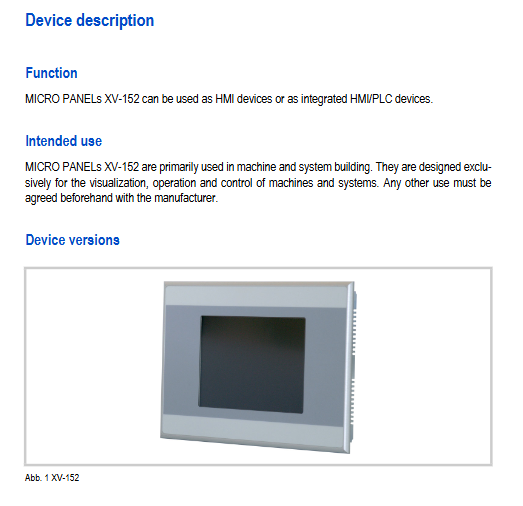
XV-152 is an industrial grade HMI/PLC integrated equipment, mainly used in the field of machine and system manufacturing. Its core functions include visual display of industrial equipment, manual operation control, data acquisition and communication. It supports independent use as HMI or integration of PLC functions, without built-in operating system description, and needs to be used in conjunction with Windows CE system and XSoft-CoDeSys-2 programming tool.
Core version and specifications
The device is divided into two versions, D and E, with screen sizes covering 5.7 "/8.4"/10.4 ". The core configuration is as follows:
Version core differences support interface adaptation to screen size
D-version basic communication versions RS232, RS485, CAN, Profibus (by sub model) 5.7 "/8.4"/10.4“
The E version has added SmartWire DT Master RS485, CAN/Profibus (depending on the sub model) SmartWire-DT 5.7"/8.4"/10.4"
Screen and System Configuration
Category specific parameters
Screen feature type: resistive touch screen; Resolution: VGA (640 × 480); Color: 64k colors; Brightness: 350 cd/m ²; Contrast ratio: 300:1; Backlight lifespan: 40000 hours (software adjustable brightness)
System configuration processor: 32-bit RISC, 400MHz; Memory: 64MB DRAM; Storage: 64MB NAND Flash, 2MB NOR Flash, 125KB NVRAM; External storage: 1 SD card slot (supports SDA 1.00 standard, does not support SDHC)
Real time clock battery model: CR2032 (3.0V, 220mAh); Backup time: 10 years (non replaceable, welded)
Packaging Content
The basic accessories include the host, fixed brackets (4/6/8 according to size), sealing strips, and power connectors. The E-version is equipped with an additional SmartWire DT Master power connector; Optional accessories include 5 sets of touch pens (model ACCESSORIES-TP-TEN-5, part number 171192), which need to be ordered separately.
Safety Regulations
Warning symbol grading: The document adopts a three-level warning, DANGER for fatal danger, Warning for serious danger, CAUTION for minor injury/equipment damage, and there is also a general information prompt symbol ().
Personnel requirements: Only qualified and trained personnel are allowed to install/operate/maintain the equipment. All operators must read and understand the instructions thoroughly, and the use of single page content for operation is prohibited.
General safety taboos
Prohibit the use of equipment for personnel/equipment protection safety functions;
The equipment is prohibited from opening the cover, as there are live parts inside that can easily cause electric shock;
Avoid electrostatic discharge: Before contacting the equipment, touch the grounded metal and do not touch static sensitive components;
Avoid equipment condensation: After sudden changes in temperature and humidity, it is necessary to let it stand at room temperature before turning it on to prevent short circuits;
Avoid UV exposure: To prevent plastic from becoming brittle, keep away from sunlight/UV lamps;
Cleaning taboos: Do not use sharp tools/corrosive cleaning agents to prevent liquids from entering the equipment.
Requirements for use in explosive environments
Can only be used in ATEX 94/9/EC Zone 22 area (II 3D Ex tc IIIC T70 ° C IP6x);
When using Zone 22, the grounding resistance of the metal parts that can be touched should be less than 10 ^ 9 Ω to avoid beam discharge and prevent equipment from being impacted. The device must be turned off before inserting or unplugging connectors;
Installation requires the use of 8 fixed brackets to ensure sealing integrity.
Installation specifications
Installation foundation requirements
Installation position: Can be installed in control cabinets, operation panels, or workstations, supporting horizontal/vertical installation, with a vertical installation tilt angle of ≤± 45 ° (when there is no forced ventilation);
Environmental requirements: Avoid direct sunlight, with a distance of ≥ 3cm around ventilation openings and ≥ 15cm around heat sources;
Installation surface requirements: The material thickness at the opening should be 2-5mm, the flatness should be ≤ 0.5mm, and the surface roughness Rz should be ≤ 120.
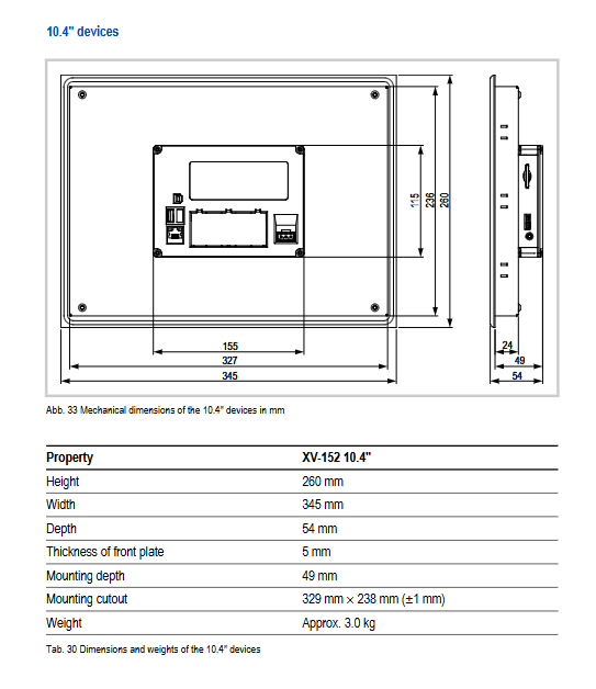
Installation opening size (± 1mm)
Screen size, hole size (length x width, mm), device size (length x width x depth, mm), weight (approximately)
5.7 inches 198 × 142 212 × 156 × 52.5 1.3kg
8.4 inches 261 × 194--
10.4 inches 329 × 238 345 × 260 × 54 3.0kg
Core interface parameters and wiring requirements
Requirements for the use of key parameters in interface names
Power supply interface 24VDC SELV, voltage range 19.2-30.0VDC (with ripple 18.0-31.2VDC); Connector: Phoenix MSTB 2.5/3-ST-5.08; Wiring cross-sectional area 0.75-2.5mm ²; Built in reverse protection and fuse with torque of 0.6-0.8Nm (only replaceable by the original factory); Functionally connected to the casing/0V, without electrical isolation
Ethernet 100Base TX/10Base-T, STP cable for RJ45 interface, crossover cable for devices, direct connection for switches, maximum length 100m
USB interface USB 2.0 (Host/Device), no electrical isolation USB Host maximum power consumption 2.5W, supports 1.5/12/480 MBit/s
SmartWire DT (E-version) POW/AUX power supply 24VDC, SWD interface supports 99 slave stations requiring external overcurrent protection (DIN standard 3A, UL standard 2A), bus rate 125/250 Kbit/s
CAN interface 9-pin D-Sub male, no electrical isolation, characteristic impedance of 120 Ω using shielded twisted pair, maximum length of 500m (0.75mm ²), supporting 32 stations
Profibus interface 9-pin D-Sub female head, no electrical isolation, characteristic impedance of 150 Ω using Profibus A-class shielded twisted pair, maximum length of 1200m, supporting 32 stations
Installation process and fixing requirements
Preparation for drilling: Process installation holes according to the corresponding dimensions to ensure that the installation surface meets the requirements;
Sealed installation: Insert the sealing strip into the groove of the front plate of the equipment (the joint should be at the bottom, without gaps/twists);
Fixed equipment: Insert the device into the installation hole from the front and fix it with a bracket from the back. For IP65/Zone 22 scenarios, 8 brackets are required with a screw torque of ≤ 0.2Nm;
Wiring debugging: Connect the cables according to the interface specifications (low impedance grounding of the shielding layer), and check the correctness of the wiring before powering on.
Operation and Maintenance
Basic Operations
Startup: The device does not have a power switch and automatically boots after being powered on. The first startup requires configuring system parameters and installing application programs;
Shutdown: Simply disconnect the power supply, and ensure that there are no SD card read or write operations before shutting down;
SD card operation: It can only be plugged in and unplugged when the device is powered off, to avoid power failure during reading and writing (software operation), and to prevent data loss or SD card damage.
Daily Maintenance
Touch screen maintenance: Clean with a clean, soft and damp cloth when contaminated. For stubborn stains, spray a small amount of cleaning agent on the cloth (corrosive agents are prohibited); Calibration is required when the touch response is abnormal (refer to the "Windows CE System Description");
Regular inspection: It is recommended to regularly check the wiring tightness, sealing integrity, and interface status according to NFPA 70B standard;
Battery maintenance: The built-in CR2032 battery is non replaceable and has a lifespan of approximately 10 years. If the battery fails, it needs to be returned to the factory for processing.
Troubleshooting (core faults)
Possible causes and solutions for the fault phenomenon
The device cannot start and the power interface is not powered. Check the connection between the power cable and the connector
Touch screen unresponsive/abnormal response uncalibrated, installation screws too tight, touch screen contamination calibrated touch screen; Loosen screws (torque ≤ 0.2Nm); Clean the touch screen
Display the backlight settings in the visualization software for black screen backlight off and backlight fault check; return to factory for repair
Prompt "Touch is dirty or defective" Touch screen contamination or uncalibrated Clean touch screen and recalibrate
Maintenance and scrapping
Maintenance restrictions: The equipment can only be opened and repaired by Eaton's original factory or authorized repair center. Unauthorized opening of the cover will result in loss of warranty;
Scrap disposal: Equipment containing lithium batteries (CR2032) must be disposed of in accordance with relevant national regulations or returned to Eaton's original factory/sales office. Unauthorized disposal is prohibited.
Summary of Core Technical Parameters
Category specific parameters
Power consumption 5.7 ": maximum 7W for base, maximum 2.5W for USB Host, total maximum 9.5W; 8.4"/10.4 ": maximum 12W for base, maximum 2.5W for USB Host, total maximum 14.5W; startup surge current: 1.5A/2s
Front protection level: IP65/Enclosure Type 4X (indoor only); Rear: IP20/Enclosure Type 1
Environmental parameters operating temperature: 0-50 ℃; Storage/transportation temperature: -20-60 ℃; Relative humidity: 10-95% (no condensation); Anti vibration: IEC/EN 60068-2-6 (5-9Hz displacement 3.5mm, 9-60Hz displacement 0.15mm, 60-150Hz acceleration 2g); Impact resistance: IEC/EN 60068-2-27 (15g/11ms)
Certification Standard EMC: 2004/108/EC; Safety: IEC/EN 60950, UL 508; Explosion protection: ATEX 94/9/EC Zone 22; Product standards: EN 50178, IEC/EN 61131-2
Materials and Packaging
Equipment material: The shell is made of galvanized steel plate, the front plate is made of anodized aluminum (Peraluman 101), the back plate is made of PC-GF, the touch back plate is made of glass+polyester film, and all shell materials are halogen-free;
Packaging material: The exterior is cardboard, and the interior is cardboard with PE foil and polyethylene (PE) plastic bags.
- YOKOGAWA
- Reliance
- ADVANCED
- SEW
- ProSoft
- WATLOW
- Kongsberg
- FANUC
- VSD
- DCS
- PLC
- man-machine
- Covid-19
- Energy and Gender
- Energy Access
- Renewable Integration
- Energy Subsidies
- Energy and Water
- Net zero emission
- Energy Security
- Critical Minerals
- A-B
- petroleum
- Mine scale
- Sewage treatment
- cement
- architecture
- Industrial information
- New energy
- Automobile market
- electricity
- Construction site
- HIMA
- ABB
- Rockwell
- Schneider Modicon
- Siemens
- xYCOM
- Yaskawa
- Woodward
- BOSCH Rexroth
- MOOG
- General Electric
- American NI
- Rolls-Royce
- CTI
- Honeywell
- EMERSON
- MAN
- GE
- TRICONEX
- Control Wave
- ALSTOM
- AMAT
- STUDER
- KONGSBERG
- MOTOROLA
- DANAHER MOTION
- Bentley
- Galil
- EATON
- MOLEX
- Triconex
- DEIF
- B&W
- ZYGO
- Aerotech
- DANFOSS
- KOLLMORGEN
- Beijer
- Endress+Hauser
- schneider
- Foxboro
- KB
- REXROTH
- YAMAHA
- Johnson
- Westinghouse
- WAGO
- TOSHIBA
- TEKTRONIX
- BENDER
- BMCM
- SMC
- HITACHI
- HIRSCHMANN
- XP POWER
- Baldor
- Meggitt
- SHINKAWA
- Other Brands
- UniOP
- KUKA
- IBA
- Beckhoff
- ADLINK
-
Beckhoff CX1100-0910 - Power Supply Module
-
Beckhoff C5210-0010 - Communication Module C5210
-
BECKHOFF KL1352 - Bus Terminal SET OF 2 FREE FAST SHIP
-
Beckhoff EL3058 - 8 x analog input single ended 4...20mA 85惟 shunt 12bit
-
Beckoff CX1100-0920 - UPS Module 24VDC (US SELLER) * *
-
BECKHOFF C6920-0000 - C69200000 PLC Moudule
-
Beckhoff CX5120-0115 - CPU controller module CX5120-0115
-
Unknown 15F5C1E-Y50A - Of Frequency Converters
-
Beckhoff AX5118-0000-0200 - Servo Drive HTP0
-
BECKHOFF AX5106-0000-0200 - Servo Drive
-
Beckhoff CX5240-0175 - Module (free) #U2327D YG
-
Beckhoff CP6607-0001-0000 - Compact PC Panel Economy Installation Operator 5,7 "
-
Beckhoff EP3744-0041 - 2022 EP37440041 Module
-
Beckhoff CP6209-0001-0020 - 6.5" PC Touch Screen Control Panel 24VDC
-
Beckhoff CX9020-0111 - /U900 +8x+2xEL3121+1x EL9410+3xEL1008+1x EL2008 Set
-
Beckhoff C6525-1030-0050 - Industrial PC
-
Beckoff CX1100-0920 - UPS Module 24VDC (US SELLER)
-
Beckhoff CX5010-0120 - CX5010 Processor Intel Atom Z510 B24
-
Siemens 6FC5203-0AF04-1BA1 - Operation Panel
-
Beckhoff CX5230-0175 - / 000029724 Embedded PC / Industrial PC on Rail
-
Beckhoff CP3916-0000 - industrielles Anzeige- und Bedienterminal
-
BECKHOFF CX1500-M310 - CX1000-N000 CX1000-0011 CX1000-C00L CX1100-0002 PLC Module
-
Beckhoff EL1872 - 16-channel digital input terminal
-
BECKHOFF EP2318-0001 - module
-
Beckhoff CX9020-0110 - Basic CPU Module
-
Beckhoff EL2564 - EtherCAT Terminal, 4-channel LED output, 5鈥?8VDC, 4A, RGBW
-
Beckhoff CX5130-0155 - /000105637 Automation Embedded PC
-
B&R 400 - Power Control Panel Rev D0 24 VDC
-
Beckhoff CX2020-0155 - module
-
Beckhoff CX9020-0115 - PLC Module
-
BECKHOFF EL6695 - PLC EL 6695
-
BECKHOFF EL7047 - PLC Modules
-
Beckhoff CX1000-0012 - Control HW 2.2 + CX1500-M310 + CX1000-C00L + CX1100-0002+
-
Beckhoff C6920-1039-0030 - control cabinet industrial PC CPU Celeron 1.90 GHz, 2 cores
-
BECKHOFF CX1100-0910 - PLC Module#
-
Beckhoff IL2301-B318-0000 - Coupler Box 4 Channel Digital Input |
-
Beckhoff CX7080 - Module
-
Beckhoff C6930-0060 - Industrial PC
-
Beckhoff CP7902-1060-0000 - Touchscreen 15 " CP7902
-
beckhoff CX9020-0111 - Controller module or UPS
-
Beckhoff CX8091 - PLC Module CX8091
-
Beckhoff C6640-1008-0030 - Control Cabinet Industrial PC
-
BECKHOFF CX1100-0920 - module
-
Beckhoff C9900-M921 - see pictures
-
BECKHOFF CP6829-0001-0000 - Touch Panel
-
BECKHOFF C6930-0060 - Industrial Computer
-
BECKHOFF CX8050 - PLC module
-
Beckhoff CP6202-0021-0020 - Touch Screen #
-
BECKHOFF AM3031-0C20-0000 - SERVO MOTOR
-
Unknown BCH1302N11A1C - Servo motor
-
Beckhoff EL2502 - 2-channel pulse width output terminal
-
Beckhoff EL6731 - Profibus Master / *Rev: 0025
-
Beckhoff CP3918-0010 - Control Panel
-
BECKHOFF CP2915-0010 - [24 MONTH WARRANTY] Control Panel
-
Beckhoff AX5203-0000-0202 - Servo Drive
-
Schneider TSXDSY64T2K - PLC OUTPUT MODULE
-
Beckhoff EP4174-0002 - Module-
-
Beckhoff IL2302-B318-0000 - Profibus Box
-
Beckhoff CP6709-0001-0000 - Touchpanel
-
BECKHOFF CX2030-0123 - Controller
-
Beckhoff CX9020-0111 - Processor Module
-
Beckhoff CX1020-0000 - CX Basic CPU Module
-
Beckhoff AX2003-AS - Servo Drive HTP0
-
Beckhoff C6240-1052-0040 - 4-086-06-3073 Industrial Computer CB1052-0003
-
Beckhoff EL1918 - 8 xTwinSAFE Input
-
Beckhoff AM8072-0R20-0000 - Servomotor
-
BECKHOFF AM8021-1B21-0000 - servo motor #T882 YS
-
Beckhoff EL6224 - 4 X Terminal IO-LINK
-
Beckhoff CX5140-0135 - embedded PC with Intel Atom processor 4 GB HW 3.6
-
Beckhoff CP7201-1000-0000 - Panel PC #
-
Beckhoff CX5130-0121 - Embedded-PC 4GB CPU Module HW 2.5 Industrial PC
-
Beckhoff AM8022-0D41-1002 - Servomotor
-
BECKHOFF CX2030-0130 - Module
-
BECKHOFF EL1872 - 16-channel digital input terminal
-
Unknown GXMMW.A203P33 - 1pc encoder
-
Beckhoff EL6631-0000 - EtherCAT Terminal 2-Port EL 6631
-
BECKHOFF C6925-0030 - Industrial Computer
-
Beckhoff CX8190 - A Module
-
BECKHOFF CX2040-0135 - CX2040-0135/000000927 CPU BASE MODULE i7 2715QE 2.1GHz --
-
BECKHOFF KL6023-0000 - Wireless adapter
-
Saia Burgess PCD7.F700 - PCD7F700 Communication Module
-
Beckhoff CX5130-0112 - CPU Module
-
BECKHOFF CX1020-N010 - CX1020-N000 CX1020-0111 CX1100-0004 EL2008 EL3064 EL4004
-
Beckhoff EP1819-0021 - A Module
-
Beckhoff CX2030-0120 - / 4gb with CX2100 0004
-
B&R X20-XC-0292 - Automation Powerlink Ethernet Bus Controller Module
-
Beckhoff BK3110 - One PLC Module
-
BECKHOFF KL3222 - PLC Module
-
BECKHOFF CX1500-M310 - CX1000-N000 CX1000-0011 CX1000-C00L CX1100-0002 PLC MODULE
-
Beckhoff CP3918-0010 - Control Panel
-
Beckhoff CX2030-0100-1002 - /4GB + CX2100 + CX2550 + CX2500-0060 + SSD
-
Beckhoff EP1816-0008 - PLC Module
-
Beckhoff CX5130-0112 - Module
-
Beckhoff Cx1500-m750 - CPU Hw: 1.4
-
BECKHOFF AX5112-0000-0200 - AX511200000200 Servo Driver
-
Beckhoff EL3751 - EtherCAT Terminal 1 Channel Analog Input Multifunction 24 Bit
-
Beckhoff CX1100-0002 - Power Supply Module
-
Beckhoff CP3916-1016-0010 - Control Panel
-
BECKHOFF CX9001-1101 - #NAME?
-
Beckhoff EP3174-0002 - EtherCAT Box Module
-
Beckhoff C6030-0070 - servo drive
-
Beckhoff CX2020-0120 - /4GB CPU, CX2100-0904, 3x EL6900, EL1904, 16GB Memory
-
BECKHOFF C6110 - BOX-PC 113608
-
BECKHOFF EK1914 - module #P
-
Beckhoff C6140 - Ipox IP-4GVI63 + CH7009A_DVI_TV + SIEMENS A5E00369843 + WD800AAJB
-
Beckhoff CX5020-0111 - controller Good quality
-
BECKHOFF C6015-0010 - / 6559380 ULTRA-COMPACT INDUSTRIAL PC ()
-
Beckhoff AX5203-0000-0200 - PLC module
-
Beckhoff EL2872 - 16-channel digital output terminal
-
BECKHOFF C3640-0000 - Panel Industrial PC 100/240VAC 128MB E0122L
-
Beckhoff CX8031 - Module
-
Beckhoff CX5020-0120-1002 - PLC module#
-
Beckhoff C6140 - M845B + SIEMENS A5E00369843 + C9900_A159_1 + AUTOMATA CAN PCI 1N
-
BECKHOFF AX5112-0000-0200 - Servo Drive*ie
-
B&R ECPA42-01 - Analog Output Module 4-Channel, +/- 10V Output Signal, 20mA Max
-
Beckhoff EL6631-0010 - PLC Module
-
BECKHOFF C6930-0070 - CONTROL CABINET INDUSTRIAL PC
-
BECKHOFF AX5112-0000-0200 - AX511200000200 Servo Driver
-
BECKHOFF EK9000 - Programmable Logic Controller Module EK9000 EK9000
-
BECKHOFF C6920-1028-0000 - Industrial computer
-
Beckhoff CX2030-0120 - controller Module
-
Beckhoff BX8000-0000 - Bus Terminal Controller HW 4.4
-
B&R 3NC154.60-2 - Positioning Module#
-
BECKHOFF CX1020-0122 - PLC module
-
Beckhoff AM3032-0D40-0000 - Servo Motor
-
BECKHOFF CX5020-0111 - CPU Module CX5020-0111
-
Beckhoff CB1051 - G5 Motherboard
-
BECKHOFF KL2641 - 1-channel relay output terminal

K-JIANG

Add: Jimei North Road, Jimei District, Xiamen, Fujian, China
Tell:+86-15305925923