
K-WANG


YOKOGAWA FIO System (compatible with Vnet/IP) Hardware Specification Manual
YOKOGAWA FIO System (compatible with Vnet/IP) Hardware Specification Manual
Positioning and core use
The "FIO (Fieldnetwork I/O) System General Specification Manual" (document number: GS 33K50F10-50E) released by Yokogawa Electric Corporation is the 8th edition updated in September 2014. Its core purpose is to guide the module selection, system deployment, installation, debugging, and compliance verification of the system in the CENTUM VP (Vnet/IP) integrated production control system. The FIO system, as a field I/O solution, focuses on the acquisition and control of industrial field signals. It is interconnected with field control units (FCUs) through multiple buses and is suitable for process control needs in industries such as petrochemicals, power, and pharmaceuticals.
System architecture and core components
(1) Overall architecture design
The FIO system adopts a layered architecture of "FCU+node unit+bus", which realizes reliable interconnection between on-site signals and control units, supports dual redundancy configuration (power module, bus interface module, I/O module), and ensures high availability operation of industrial sites. The system can achieve chain or star topology expansion through the optical ESB bus relay unit (ANT10U), adapting to centralized and distributed deployment scenarios.
(2) Classification and specifications of core components
1. On site Control Unit (FCU)
FCU is the system control core, responsible for receiving on-site signals from FIO node units and executing control logic. The specific model and characteristics are as follows:
Model series type installation method adaptation bus core characteristics
AFV30 (S/D) standard/dual redundant 19 inch rack mounted ESB bus and optical ESB bus support node expansion package, connecting up to 13 node units
AFV40 (S/D) standard/dual redundant integrated ESB bus with cabinet, optical ESB bus. A single cabinet can install up to 11 node units and relay units
AFV10 (S/D) standard/dual redundant 19 inch rack mounted ESB bus, ER bus miniaturization design, suitable for small and medium-sized control scenarios
2. Node unit
Node units are interface carriers for on-site I/O signals, integrating power modules, bus interface modules, and I/O modules. They are divided into three categories according to the adapted bus:
Node unit type, model series, redundancy support, adaptation to bus core usage
ESB bus node unit ANB10 (S/D) single/dual redundant ESB bus close range (≤ 10m) on-site signal acquisition and transmission
Optical ESB bus node unit ANB11 (S/D) single/dual redundant optical ESB bus long-distance (up to 50km) anti-interference signal transmission
ER bus node unit ANR10 (S/D) single/dual redundant ER bus medium short distance (≤ 185m) economical signal transmission
3. Relay unit
Model Name Core Function Adaptation Scenarios
ANT10U optical ESB bus relay unit optical ESB bus chain/star expansion, amplifying optical signals for cross plant and long-distance node interconnection
4. Bus interface module
Used to achieve bus interconnection between FCU and node units, the key models and characteristics are as follows:
Model name adaptation bus core parameter installation requirements
EC401 ESB bus coupler module ESB bus single module can connect up to 9 node units AFV30 /AFV40 /AFV10 , which need to be installed in slots 7/8
EC402 2-port ESB bus coupler module, with 9 node units connected to each of the upper and lower ports of the ESB bus, is only compatible with AFV30/AFV40
The EB401 ER bus interface main module ER bus supports dual redundant communication. The single module is installed in odd numbered slots, and the slot on the right side needs to be left blank
ANT401/ANT411 Optical ESB Bus Relay Main Module Optical ESB Bus Transmission Distance 5km/5-50km Only compatible with AFV30 /AFV40
ANT502/ANT512 optical ESB bus relay module cooperates with the main module to achieve long-distance expansion, pre installed in the ANB11 node unit
Detailed Explanation of Bus System Specifications
The FIO system supports three types of buses: ESB, optical ESB, and ER, adapting to different distance and bandwidth requirements. The core specifications are as follows:
(1) ESB bus (AFV full series FCU adaptation)
Application scenario: Close range interconnection between FCU and local node units;
Transmission parameters: speed of 128 Mbps, bus topology, dual redundancy support;
Transmission medium: dedicated cable (YCB301), maximum transmission distance of 10m;
Connection capacity: AFV30 /AFV40 (LFS1700 database) up to 3 node units, with a maximum of 13 after expansion; AFV10 (LFS1500 database) has a maximum of 3 node units, and can be expanded to a maximum of 9.
(2) Optical ESB bus (AFV30 /AFV40 adaptation)
Application scenario: Long distance, anti-interference node interconnection;
Transmission parameters: speed of 128 Mbps, chain/star topology, dual redundancy support;
Transmission medium: Quartz single-mode fiber (JIS C6835 SSMA-9.3/125), LC interface, 2-core;
Transmission distance: 10m without relay, up to 50km with ANT411 relay;
Connection capacity: Share node unit quota with ESB bus.
(3) ER bus (AFV10 adaptation)
Application scenario: Medium to short distance economic interconnection;
Transmission parameters: speed of 10 Mbps, bus topology, dual redundancy support;
Transmission medium: coaxial cable (YCB141/YCB311), which needs to be interconnected through YCB147/YCB149 bus adapters;
Transmission distance: YCB141 has a maximum length of 185m; when using mixed cables, it is necessary to meet the requirement of "YCB141 length+(185/500) × YCB311 length ≤ 185m";
Connection capacity: up to 3 node units for AFV10 (LFS1500 database), up to 14 after expansion, and up to 8 node units for a single bus.
I/O module classification and core parameters
The FIO system I/O modules cover four categories: analog, digital, communication, and turbine machinery. They support isolation switch type and built-in isolation grid type, and are compatible with various field signals. The core classifications and parameters are as follows:
(1) Analog I/O module
It includes three types: non isolated, isolated, and channel isolated, supporting current, voltage, TC/mV, and RTD/PAT signals. Representative models are as follows:
Model Name Channel Number Signal Type Isolation Characteristics Power Consumption (5V DC/24V DC) Explosion proof Support
AAI141 analog input module 16 4-20 mA non isolated 310 mA/450 mA CSA/FM spark free type
AAV141 analog input module 16 1-5 V non isolated 350 mA/- CSA/FM spark free type
AAI143 analog input module 16 4-20 mA isolated 230 mA/540 mA Type i (intrinsic safety type)
AAI543 analog output module 16 4-20 mA isolated 230 mA/540 mA Type i (intrinsic safety type)
AAT141 TC/mV input module 16 TC (J/K/E, etc.), -100-150 mV isolated 450 mA/- CSA/FM spark free type
AAR181 RTD input module 12 Pt100 Ω isolated 450 mA/- CSA/FM spark free type
ASI133 built-in isolation barrier analog input module 4-20 mA isolation 150 mA/450 mA Type i (intrinsic safety type)
AST143 built-in isolation barrier TC/mV input module 16 TC, -100-150 mV isolation 150 mA/80 mA Type i (intrinsic safety type)
(2) Digital I/O module
Supports DC, AC, and relay outputs, partially compatible with NAMUR standards. Representative models are as follows:
Model Name Channel Number Signal Type Isolation Characteristics Power Consumption (5V DC) Explosion proof Support
ADV151 digital input module 32 24 V DC isolated 500 mA CSA/FM spark free type
ADV551 digital output module 32 24 V DC isolated 700 mA CSA/FM spark free type
ADV141 digital input module 16 100-120 V AC isolated 500 mA CSA/FM spark free type
ADR541 relay output module 16 24-110 V DC/100-240 V AC isolated 780 mA CSA/FM spark free type
ASD143 built-in isolation barrier digital input module 16 NAMUR compatible isolation 150 mA Type i (intrinsic safety type)
ASD533 built-in isolation barrier digital output module 8 U>12 V (I=40 mA) isolation 150 mA Type i (intrinsic safety type)
(3) Communication module
Support multiple industrial communication protocols to achieve interconnection with third-party devices:
Model Name Port Number Communication Protocol Rate Power Consumption (5V DC)
ALR111 serial communication module 2 RS-232C 1200 bps-115.2 kbps 500 mA
ALR121 serial communication module 2 RS-422/RS-485 1200 bps-115.2 kbps 500 mA
ALE111 Ethernet Communication Module 1 Ethernet 10 Mbps 500 mA
ALF111 Foundation Fieldbus Module 4 FF-H1 31.25 kbps 500 mA
ALP111/ALP121 PROFIBUS-DP module 1 PROFIBUS-DP -700 mA
(4) Turbomachinery specialized module
Suitable for turbomachinery control scenarios, the core models are as follows:
Model Name Channel Number Function Power Consumption (5V DC) Environment Support
AGS813 servo module 12 servo control 500 mA G3 support
AGP813 high-speed protection module 26 device security protection 900 mA G3 support
(5) Compatible module
Designed for upgrading the CENTUM V, CENTUM-XL, and µ XL systems, it can reuse existing cables. Representative models include AAP149 (pulse input), AAP849 (pulse input/analog output), and ADV859-ADV569 (ST compatible digital I/O).
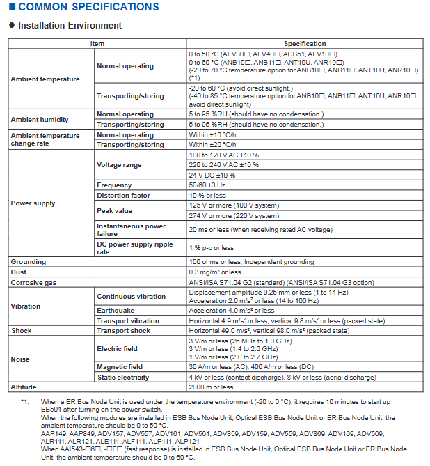
Environmental and power specifications
(1) Environmental requirements
Environmental parameters, working status, transportation/storage status, special instructions
Temperature standard: 0-50 ℃ (AFV series)/0-60 ℃ (node unit); Wide temperature options: -20-70 ℃ Wide temperature options: -40-85 ℃ ER node unit -20-0 ℃ Start up requires 10 minutes of preheating
Humidity 5-95% RH (no condensation) 5-95% RH (no condensation)-
Temperature change rate ± 10 ℃/h ± 20 ℃/h-
Vibration 1-14Hz: displacement ≤ 0.25mm; 14-100Hz: acceleration ≤ 2.0 m/s ² Earthquake: horizontal ≤ 4.9 m/s ²; Vertical ≤ 9.8 m/s ² in packaging state
Dust ≤ 0.3 mg/m ³ --
Corrosive gas standard: ANSI/ISA S71.04 G2; Option: G3--
Electromagnetic environment electric field ≤ 3 V/m (26MHz-2GHz); Magnetic field ≤ 30 A/m (AC)/400 A/m (DC) --
Static protection contact discharge ≤ 4 kV; air discharge ≤ 8 kV --
Altitude ≤ 2000 meters --
(2) Power specifications
Communication input: 100-120 V AC (± 10%) or 220-240 V AC (± 10%), frequency 50/60Hz (± 3Hz), distortion ≤ 10%, peak value ≥ 125 V (100V system)/274 V (220V system);
DC input: 24 V DC (± 10%), ripple rate ≤ 1% p-p;
Instantaneous power outage tolerance: ≤ 20ms (under rated AC voltage);
Grounding requirements: independent grounding, grounding resistance ≤ 100 Ω.
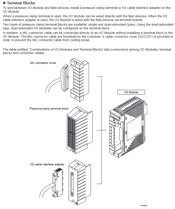
Connection method and terminal configuration
(1) Signal connection method
The module supports three connection methods to adapt to different on-site wiring requirements:
Pressure clamping terminal: directly connected to on-site equipment, supporting single/double redundant terminal blocks (such as ATA4S/ATA4D);
Special cable: Connect the terminal board through KS cable interface adapter, and some modules can be directly wired (such as YCB331/YCB337);
MIL connector cable: No terminal block required, directly connected to the module, equipped with anti loosening sheath (ACCC01).
(2) Compatibility of key module connections
Module type pressure clamping terminal dedicated cable MIL connector cable
Analog I/O (AAI141/AAI543) Support Support Support
Digital I/O (ADV151/ADV551) supports partial support
Communication module (ALF111/ALP111) partially supported but not supported
Built in isolation barrier module (ASI133/ASD143) is not supported
Compatibility module (AAP149/ADV859) is not supported
- YOKOGAWA
- Reliance
- ADVANCED
- SEW
- ProSoft
- WATLOW
- Kongsberg
- FANUC
- VSD
- DCS
- PLC
- man-machine
- Covid-19
- Energy and Gender
- Energy Access
- Renewable Integration
- Energy Subsidies
- Energy and Water
- Net zero emission
- Energy Security
- Critical Minerals
- A-B
- petroleum
- Mine scale
- Sewage treatment
- cement
- architecture
- Industrial information
- New energy
- Automobile market
- electricity
- Construction site
- HIMA
- ABB
- Rockwell
- Schneider Modicon
- Siemens
- xYCOM
- Yaskawa
- Woodward
- BOSCH Rexroth
- MOOG
- General Electric
- American NI
- Rolls-Royce
- CTI
- Honeywell
- EMERSON
- MAN
- GE
- TRICONEX
- Control Wave
- ALSTOM
- AMAT
- STUDER
- KONGSBERG
- MOTOROLA
- DANAHER MOTION
- Bentley
- Galil
- EATON
- MOLEX
- Triconex
- DEIF
- B&W
- ZYGO
- Aerotech
- DANFOSS
- KOLLMORGEN
- Beijer
- Endress+Hauser
- schneider
- Foxboro
- KB
- REXROTH
- YAMAHA
- Johnson
- Westinghouse
- WAGO
- TOSHIBA
- TEKTRONIX
- BENDER
- BMCM
- SMC
- HITACHI
- HIRSCHMANN
- XP POWER
- Baldor
- Meggitt
- SHINKAWA
- Other Brands
- UniOP
- KUKA
- IBA
- Beckhoff
- ADLINK
-
Beckhoff CX1100-0910 - Power Supply Module
-
Beckhoff C5210-0010 - Communication Module C5210
-
BECKHOFF KL1352 - Bus Terminal SET OF 2 FREE FAST SHIP
-
Beckhoff EL3058 - 8 x analog input single ended 4...20mA 85惟 shunt 12bit
-
Beckoff CX1100-0920 - UPS Module 24VDC (US SELLER) * *
-
BECKHOFF C6920-0000 - C69200000 PLC Moudule
-
Beckhoff CX5120-0115 - CPU controller module CX5120-0115
-
Unknown 15F5C1E-Y50A - Of Frequency Converters
-
Beckhoff AX5118-0000-0200 - Servo Drive HTP0
-
BECKHOFF AX5106-0000-0200 - Servo Drive
-
Beckhoff CX5240-0175 - Module (free) #U2327D YG
-
Beckhoff CP6607-0001-0000 - Compact PC Panel Economy Installation Operator 5,7 "
-
Beckhoff EP3744-0041 - 2022 EP37440041 Module
-
Beckhoff CP6209-0001-0020 - 6.5" PC Touch Screen Control Panel 24VDC
-
Beckhoff CX9020-0111 - /U900 +8x+2xEL3121+1x EL9410+3xEL1008+1x EL2008 Set
-
Beckhoff C6525-1030-0050 - Industrial PC
-
Beckoff CX1100-0920 - UPS Module 24VDC (US SELLER)
-
Beckhoff CX5010-0120 - CX5010 Processor Intel Atom Z510 B24
-
Siemens 6FC5203-0AF04-1BA1 - Operation Panel
-
Beckhoff CX5230-0175 - / 000029724 Embedded PC / Industrial PC on Rail
-
Beckhoff CP3916-0000 - industrielles Anzeige- und Bedienterminal
-
BECKHOFF CX1500-M310 - CX1000-N000 CX1000-0011 CX1000-C00L CX1100-0002 PLC Module
-
Beckhoff EL1872 - 16-channel digital input terminal
-
BECKHOFF EP2318-0001 - module
-
Beckhoff CX9020-0110 - Basic CPU Module
-
Beckhoff EL2564 - EtherCAT Terminal, 4-channel LED output, 5鈥?8VDC, 4A, RGBW
-
Beckhoff CX5130-0155 - /000105637 Automation Embedded PC
-
B&R 400 - Power Control Panel Rev D0 24 VDC
-
Beckhoff CX2020-0155 - module
-
Beckhoff CX9020-0115 - PLC Module
-
BECKHOFF EL6695 - PLC EL 6695
-
BECKHOFF EL7047 - PLC Modules
-
Beckhoff CX1000-0012 - Control HW 2.2 + CX1500-M310 + CX1000-C00L + CX1100-0002+
-
Beckhoff C6920-1039-0030 - control cabinet industrial PC CPU Celeron 1.90 GHz, 2 cores
-
BECKHOFF CX1100-0910 - PLC Module#
-
Beckhoff IL2301-B318-0000 - Coupler Box 4 Channel Digital Input |
-
Beckhoff CX7080 - Module
-
Beckhoff C6930-0060 - Industrial PC
-
Beckhoff CP7902-1060-0000 - Touchscreen 15 " CP7902
-
beckhoff CX9020-0111 - Controller module or UPS
-
Beckhoff CX8091 - PLC Module CX8091
-
Beckhoff C6640-1008-0030 - Control Cabinet Industrial PC
-
BECKHOFF CX1100-0920 - module
-
Beckhoff C9900-M921 - see pictures
-
BECKHOFF CP6829-0001-0000 - Touch Panel
-
BECKHOFF C6930-0060 - Industrial Computer
-
BECKHOFF CX8050 - PLC module
-
Beckhoff CP6202-0021-0020 - Touch Screen #
-
BECKHOFF AM3031-0C20-0000 - SERVO MOTOR
-
Unknown BCH1302N11A1C - Servo motor
-
Beckhoff EL2502 - 2-channel pulse width output terminal
-
Beckhoff EL6731 - Profibus Master / *Rev: 0025
-
Beckhoff CP3918-0010 - Control Panel
-
BECKHOFF CP2915-0010 - [24 MONTH WARRANTY] Control Panel
-
Beckhoff AX5203-0000-0202 - Servo Drive
-
Schneider TSXDSY64T2K - PLC OUTPUT MODULE
-
Beckhoff EP4174-0002 - Module-
-
Beckhoff IL2302-B318-0000 - Profibus Box
-
Beckhoff CP6709-0001-0000 - Touchpanel
-
BECKHOFF CX2030-0123 - Controller
-
Beckhoff CX9020-0111 - Processor Module
-
Beckhoff CX1020-0000 - CX Basic CPU Module
-
Beckhoff AX2003-AS - Servo Drive HTP0
-
Beckhoff C6240-1052-0040 - 4-086-06-3073 Industrial Computer CB1052-0003
-
Beckhoff EL1918 - 8 xTwinSAFE Input
-
Beckhoff AM8072-0R20-0000 - Servomotor
-
BECKHOFF AM8021-1B21-0000 - servo motor #T882 YS
-
Beckhoff EL6224 - 4 X Terminal IO-LINK
-
Beckhoff CX5140-0135 - embedded PC with Intel Atom processor 4 GB HW 3.6
-
Beckhoff CP7201-1000-0000 - Panel PC #
-
Beckhoff CX5130-0121 - Embedded-PC 4GB CPU Module HW 2.5 Industrial PC
-
Beckhoff AM8022-0D41-1002 - Servomotor
-
BECKHOFF CX2030-0130 - Module
-
BECKHOFF EL1872 - 16-channel digital input terminal
-
Unknown GXMMW.A203P33 - 1pc encoder
-
Beckhoff EL6631-0000 - EtherCAT Terminal 2-Port EL 6631
-
BECKHOFF C6925-0030 - Industrial Computer
-
Beckhoff CX8190 - A Module
-
BECKHOFF CX2040-0135 - CX2040-0135/000000927 CPU BASE MODULE i7 2715QE 2.1GHz --
-
BECKHOFF KL6023-0000 - Wireless adapter
-
Saia Burgess PCD7.F700 - PCD7F700 Communication Module
-
Beckhoff CX5130-0112 - CPU Module
-
BECKHOFF CX1020-N010 - CX1020-N000 CX1020-0111 CX1100-0004 EL2008 EL3064 EL4004
-
Beckhoff EP1819-0021 - A Module
-
Beckhoff CX2030-0120 - / 4gb with CX2100 0004
-
B&R X20-XC-0292 - Automation Powerlink Ethernet Bus Controller Module
-
Beckhoff BK3110 - One PLC Module
-
BECKHOFF KL3222 - PLC Module
-
BECKHOFF CX1500-M310 - CX1000-N000 CX1000-0011 CX1000-C00L CX1100-0002 PLC MODULE
-
Beckhoff CP3918-0010 - Control Panel
-
Beckhoff CX2030-0100-1002 - /4GB + CX2100 + CX2550 + CX2500-0060 + SSD
-
Beckhoff EP1816-0008 - PLC Module
-
Beckhoff CX5130-0112 - Module
-
Beckhoff Cx1500-m750 - CPU Hw: 1.4
-
BECKHOFF AX5112-0000-0200 - AX511200000200 Servo Driver
-
Beckhoff EL3751 - EtherCAT Terminal 1 Channel Analog Input Multifunction 24 Bit
-
Beckhoff CX1100-0002 - Power Supply Module
-
Beckhoff CP3916-1016-0010 - Control Panel
-
BECKHOFF CX9001-1101 - #NAME?
-
Beckhoff EP3174-0002 - EtherCAT Box Module
-
Beckhoff C6030-0070 - servo drive
-
Beckhoff CX2020-0120 - /4GB CPU, CX2100-0904, 3x EL6900, EL1904, 16GB Memory
-
BECKHOFF C6110 - BOX-PC 113608
-
BECKHOFF EK1914 - module #P
-
Beckhoff C6140 - Ipox IP-4GVI63 + CH7009A_DVI_TV + SIEMENS A5E00369843 + WD800AAJB
-
Beckhoff CX5020-0111 - controller Good quality
-
BECKHOFF C6015-0010 - / 6559380 ULTRA-COMPACT INDUSTRIAL PC ()
-
Beckhoff AX5203-0000-0200 - PLC module
-
Beckhoff EL2872 - 16-channel digital output terminal
-
BECKHOFF C3640-0000 - Panel Industrial PC 100/240VAC 128MB E0122L
-
Beckhoff CX8031 - Module
-
Beckhoff CX5020-0120-1002 - PLC module#
-
Beckhoff C6140 - M845B + SIEMENS A5E00369843 + C9900_A159_1 + AUTOMATA CAN PCI 1N
-
BECKHOFF AX5112-0000-0200 - Servo Drive*ie
-
B&R ECPA42-01 - Analog Output Module 4-Channel, +/- 10V Output Signal, 20mA Max
-
Beckhoff EL6631-0010 - PLC Module
-
BECKHOFF C6930-0070 - CONTROL CABINET INDUSTRIAL PC
-
BECKHOFF AX5112-0000-0200 - AX511200000200 Servo Driver
-
BECKHOFF EK9000 - Programmable Logic Controller Module EK9000 EK9000
-
BECKHOFF C6920-1028-0000 - Industrial computer
-
Beckhoff CX2030-0120 - controller Module
-
Beckhoff BX8000-0000 - Bus Terminal Controller HW 4.4
-
B&R 3NC154.60-2 - Positioning Module#
-
BECKHOFF CX1020-0122 - PLC module
-
Beckhoff AM3032-0D40-0000 - Servo Motor
-
BECKHOFF CX5020-0111 - CPU Module CX5020-0111
-
Beckhoff CB1051 - G5 Motherboard
-
BECKHOFF KL2641 - 1-channel relay output terminal

K-JIANG

Add: Jimei North Road, Jimei District, Xiamen, Fujian, China
Tell:+86-15305925923