
K-WANG


SIEMENS SIMATIC S7 300/400 operates MICROMASTER 4 (MM4) frequency converter through Profibus DP
Set value transmission: Loop the speed set value in the form of percentages from * * -100% to+100% * *, and any changes will take effect in real-time.
Status feedback: Output signals such as motor rotation direction (O-Right/O-Left), actual frequency (O-Actual_frequency, range -100% to+100%), and shutdown status (O-STOP).
SIEMENS SIMATIC S7 300/400 operates MICROMASTER 4 (MM4) frequency converter through Profibus DP
Core purpose and value of functional blocks
inverter control
Implement motor start stop: supports regular start stop (dependent on P1120 ramp up time, P1121 ramp down time) and quick stop (dependent on P1135 OFF3 ramp down time).
Set value transmission: Loop the speed set value in the form of percentages from * * -100% to+100% * *, and any changes will take effect in real-time.
Status feedback: Output signals such as motor rotation direction (O-Right/O-Left), actual frequency (O-Actual_frequency, range -100% to+100%), and shutdown status (O-STOP).
Automatic debugging
Batch/Replacement Scenario Adaptation: When debugging multiple MM4 units in bulk or replacing a single faulty unit, there is no need for PG/PC or professional debugging software. The PLC can automatically complete the parameter configuration of the new MM4.
Simplified debugging process: including quick debugging (P0010=1), motor recognition (requires motor cold state), and saturation characteristic recognition (only supported by MM440).
parameter management
Full parameter read and write: Read and write all parameters of MM4 through PKW communication, and the OP (operation panel) only supports parameter reading.
Parameter backup: Store the debugged parameters in the PLC's parameter DB (data block) for easy recovery in the future.
Diagnostic function
Multi dimensional error monitoring: covering MM4 faults/alarms, Profibus DP errors, parameter transmission errors, and automatic debugging errors.
Historical data recording: stores the latest and historical fault/alarm information (such as the fault codes and values of the last 3 faults), supports fault reset (I_RESET_Corr).
Scope and Limitations of Application
3.1 Applicable Equipment
Equipment type, specific model/specification
MM4 frequency converter MM411 V1.10, MM420 V1.17, MM430 V2.00, MM440 V2.05
Controller SIMATIC S7 300 (CPU 313-2DP and above) S7 400、C7、SINUMERIK
3.2 Not Applicable Devices and Limitations
Not applicable to controllers: SIMATIC S7 200, SIMATIC S5.
Function limitation: The system does not monitor whether the startup signal (I_Enable) meets safety conditions, and users need to provide additional protection in the program.
Installation and configuration process
4.1 Scenario without Drive ES Basic and Starter
Hardware configuration: Set the Profibus DP address of MM4 (no need to reset to factory settings).
HW Config operation:
Start HW Config in Step 7 and configure PLC hardware.
Select "MICROMASTER 4" in the "PROFIBUS-DP/SIMOVERT Catalog" and specify the DP address.
Select slot 1 and configure PPO type as PPO1 (4 PKW+2 PZD).
Program loading:
Save and compile HW Config, download to PLC module.
Copy the program blocks and symbol table from the functional block example to the user program, adapt them, load them into the PLC, and start them.
Debugging startup: Call the MM4 diagnostic interface of OP to troubleshoot DP errors, enter the debugging interface to enter motor data, start automatic debugging (set I2 Enable=0, I2 Enable QC=1, IOU_ Parameters=1), and execute motor recognition after completion.
4.2 Scenarios with Drive ES Basic and Starter
Hardware configuration: Follow step 1 of section 4.1 to set the DP address of MM4.
HW Config operation:
Configure PLC and MM4, select the corresponding MM4 version (refer to the equipment nameplate, such as "A01/2.05" corresponding to version 2.0x).
Pre allocate PPO type as PPO1 (PKW+PZD-2/2), fill in the I/O address of MM4 (PKW starting address, PZD address is PKW address+8).
Program and OP adaptation:
Load the program block and symbol table in step 3 of section 4.1.
Install OP project and adapt to "MM4" and "ParameterDB" text lists.
Debugging startup: The first debugging can be completed through Starter, and the parameters can be entered into the parameter DB; or the OP debugging interface can be directly called, and the subsequent process is the same as step 4 in 4.1.
Detailed explanation of key functions
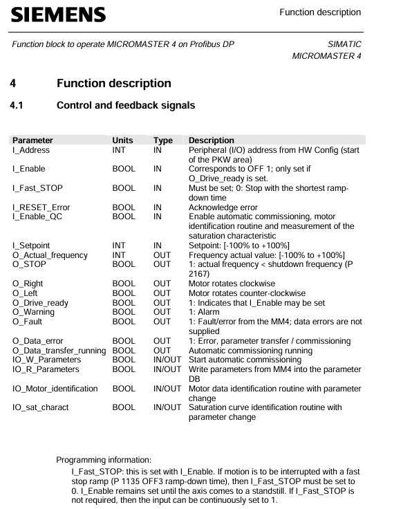
5.1 Definition of Control and Feedback Signals
Parameter Name Type Direction Unit/Range Description
The starting I/O address of the PKW area configured in the I-Address INT IN - HW Config
I-Enable BOOL IN - Variable frequency drive enable signal, can only be set when O-Drive-ready=1
I-Fast-STOP BOOL IN - Fast Shutdown Signal: 0=Fast Shutdown (using P1135), 1=Normal Shutdown (default can be set to 1)
Setpoint INT IN -100~+100 speed setting value (percentage)
Actual operating frequency INT OUT -100~+100 (percentage)
O-Drive-ready BOOL OUT - Inverter ready signal: must meet the requirements of "shutdown, I-Fast-STOP=1, no faults, no debugging in progress"
O-Fault BOOL OUT - MM4 fault signal (excluding data transmission errors)
O-Data_ error BOOL OUT - Parameter transmission/automatic debugging error signal
IOU_ Parameters BOOL IN/OUT - Start automatic debugging signal (user set 1 to start, clear 0 after FB is completed)
5.2 Automatic Debugging Process
5.2.1 Parameter DB adaptation
Motor data area: Enter the required parameters for quick debugging (P0010=1), using motor dataset 0 by default; Multiple parameter DBs need to be created for multiple datasets, which can be specified through Z_Sotor_data_SBNr.
Technical data area: Enter other parameters that are not quick debugging, support sub parameters (sub parameter 0 is the first, such as data [2] indicating the presence of sub parameters 0 and 1), and match the data type of the parameters.
5.2.2 Parameter input method
Operation steps for input method
Method 1: The frequency converter has been debugged and set to I2 Enable=0 and I2 Enable QC=1;
2. Set IOUR_Parameters=1 to start data reading;
3. O-Data_transfer_running=1 indicates that the transfer is in progress, and after completion, IOUR_Parameters will automatically clear 0.
Method 2: 1. Enter parameters directly on the OP interface (only display the parameters that need to be changed);
2. Use initial values for other parameters and support leaving the DB list empty (for easy OP indirect addressing).
5.2.3 Automatic Debugging Steps
Restore MM4 to factory settings.
Perform quick debugging (transfer motor data area parameters).
Transmission technology data area parameters.
Save the parameters to the EEPROM of MM4.
After debugging is completed, perform motor identification (ensuring that there are no errors during debugging and the motor is in a cold state).
5.3 Parameter transmission mechanism
Communication method: Based on PKW communication, it supports three parallel parameter read/write requests (Job_1~Job_3), which are executed in the order of Job_1 → Job_2 → Job_3.
Request block structure (taking Job_1 as an example):
|Parameter Name | Type | Initial Value | Description|
|Job_1. Parameter-N | INT | 0 | Target parameter number (e.g. 1002 represents fixed frequency 2)|
|Job_1. Index | INT | 0 | Sub parameter number (set 0 when there is no sub parameter, set the last sub parameter number when there are multiple sub parameters)|
|Job_1. Identifier | Byte | B # 16 # 0 | Operation type: 1=Read single parameter, 2=Write RAM, 3=Write EEPROM, 11=Read multiple sub parameters, etc|
|Job_1. Value_2~2 | DINT | L # 0 | Transferred parameter values (used as needed, such as using only Value_0 for a single parameter)|
Control signal: Job.RWRequest_1~3 are request trigger signals (user set 1 to start, clear 0 after FB is completed); Data_fault.Job.RWRequest_1~3 are error signals corresponding to the requests.
5.4 Diagnostic mechanism
5.4.1 Classification of Error Sources
Malfunctions/alarms of MM4 (such as overcurrent and overvoltage).
Fault of standard FC (SFC14/SFC15).
The functional block itself is malfunctioning.
Parameter transmission and automatic debugging errors.
5.4.2 Key diagnostic signals and displays
Parameter Name Type Direction Description
When there is an alarm for O-Warning BOOL OUT, it is 1
O-Fault BOOL OUT MM4 fault is 1 (excluding data errors)
Resetting signal: clearing MM4 fault and data error display, interrupting debugging process (without interrupting parameter transmission)
Data_fault.Nr. INT STAT error number (e.g. 0=illegal parameter number, 17=request execution not allowed in running state)
Data_fault.DP_Add_info HEX STAT DP error details (e.g. 8090=no module specified address, corresponding to SFC14/SFC15 error)
Error code description
6.1 Data_fault.Nr. (Parameter transmission and debugging errors)
Error Number Meaning Remarks
0 Illegal Parameter Number (PNU) parameter does not exist in MM4
The parameter value cannot be modified. This parameter is a monitoring type parameter and can only be read
17. Due to operational status, the task cannot be executed. The current MM4 status does not support this request (such as changing motor data during operation)
25 DP error needs to be viewed in conjunction with Data_fault.DP_Add_info for details
Parameter number 1001 is currently not activated and depends on the running status of MM4. It can be operated after activation
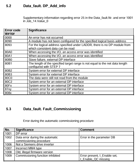
6.2 Data_fault.DP_Add_info (DP Error Supplement)
Meaning of Error Code (W # 16 #)
8090 specifies logical address without configuration module
80A0 recognized access error while accessing I/O
The target range length of 80B0 does not match the network data length configured in Step 7
6.3 Data_fault.Fault_Commission
Error Number Meaning Remarks
1001 DP error needs to be investigated for Profibus DP connection and address configuration
1002 automatic debugging data error parameter DB has errors (such as parameter values exceeding the range)
1007 MM4 model incorrectly configured MM4 model does not match the actual connected device
Functional Block Technical Data
Project specifications
Block type FB
Block Name MM4
Generate language STL
Local data 36 bytes
MC7 code length 3166 bytes
Load memory requirement 4244 bytes
Working memory requirement 3202 bytes
- YOKOGAWA
- Reliance
- ADVANCED
- SEW
- ProSoft
- WATLOW
- Kongsberg
- FANUC
- VSD
- DCS
- PLC
- man-machine
- Covid-19
- Energy and Gender
- Energy Access
- Renewable Integration
- Energy Subsidies
- Energy and Water
- Net zero emission
- Energy Security
- Critical Minerals
- A-B
- petroleum
- Mine scale
- Sewage treatment
- cement
- architecture
- Industrial information
- New energy
- Automobile market
- electricity
- Construction site
- HIMA
- ABB
- Rockwell
- Schneider Modicon
- Siemens
- xYCOM
- Yaskawa
- Woodward
- BOSCH Rexroth
- MOOG
- General Electric
- American NI
- Rolls-Royce
- CTI
- Honeywell
- EMERSON
- MAN
- GE
- TRICONEX
- Control Wave
- ALSTOM
- AMAT
- STUDER
- KONGSBERG
- MOTOROLA
- DANAHER MOTION
- Bentley
- Galil
- EATON
- MOLEX
- Triconex
- DEIF
- B&W
- ZYGO
- Aerotech
- DANFOSS
- KOLLMORGEN
- Beijer
- Endress+Hauser
- schneider
- Foxboro
- KB
- REXROTH
- YAMAHA
- Johnson
- Westinghouse
- WAGO
- TOSHIBA
- TEKTRONIX
- BENDER
- BMCM
- SMC
- HITACHI
- HIRSCHMANN
- XP POWER
- Baldor
- Meggitt
- SHINKAWA
- Other Brands
- UniOP
- KUKA
- IBA
- Beckhoff
-
LTI SC52.0040.0012.0000.0 - Servo Drive
-
Lti SC52.0040.0012.0000.0 - Servo Drive
-
Milton Industries LTI Tool By Milton LT1240 - 1/2" Drive Lugnut Remover
-
LTi Drives SO84.200.P030.0000.0-W - Servo Spindle Drive
-
LTI DRIVES LSP08-035-320-30-B0R1PY170 - Servo Motor
-
LTI DRIVES SE84.200.SC00.0001.0-W - Servo Drive
-
Lust CDE34.005.W2.2 - Lti Drives Controller
-
LTi SO84.012.0030.0011.2 - ServoOne Servo Drive
-
LTi Drives SO CM-P.0010.11.00.0 - Servo Drive Controller
-
LTi CDE34.017.W3.0 - Servo Drive
-
LTI Drives CDB32.004, C2.0,SH - Positioning Controller
-
LUST CM-CAN1 - LTi DRIVES Communication Module
-
LTi SO84.012.1030.0000.2 - Servo Drive
-
LTI MOOG CDE54.044 - PITCHMASTER FREQUENCY CONVERTER 181-01019
-
MOOG LTI 181-01019 CDE54.044 - PITCHMASTER FREQUENCY CONVERTER
-
Lust LTi Drives CDE34.010,D2.0 - Servo Drive Controller
-
LTI SO84.032.0003.0101.2 - Servo Drive
-
Seagate 9CC132-302 Harris LTI-CS IRT-34-0021-01 - Hard Drive 160GB
-
LTI SO84.032.0003.0001.2 - Servo Drive
-
LTI SO24.007.0070.0000.1 - SERVO CONTROLLER
-
LTi drive CDA32.003.C3.0.H05-01.PC1 - Servo Drive
-
LTI SO84.016.0030.0000.2 - SERVO CONTROLLER
-
LUST LTI CD A34.008,W1.4, BR - SERVO DRIVE
-
MOOG LTI 181-01019 CDE54.044 - PITCHMASTER FREQUENCY CONVERTER
-
LTI MOOG 181-01019 - PITCH Master Servo Drive CDE54.044
-
LTI SERVO ONE SO84.045.0030.0001.2-W - Drive
-
LUST LTi SO84.032.0040.0000.2 - SERVO ONE DRIVE
-
LTi Drives LSH-074-2-30-3 20/T1,G6.1M - SERVO MOTOR
-
LTI SO84.016.0000.0101.2 - servo drive
-
LTI SA54.0550.0033.0000.0 - Servo Drive
-
LTI SA54.0550.0033.0000.0 - Servo Drive
-
LTI LT 4850 - 3/8" Drive 3-Pc Twist Socket Transmission Drain Plug Removal System
-
LTI Tools LT4400-30 Lock Technology - 3/4" Twist Socket 1/2" Drive Lugnut Remover
-
LTI Tools LT-1400C - 1/2 Drive Wheel Torque Extension Tool
-
LTI Tools LT1250 - 1/2" Drive Dual Sided Socket Lug Nut Remover Tool
-
LTI SO84.032.0003.0101.2 - Servo Drive
-
LTI MOOG 181-01019 - PITCH Master Servo Drive CDE54.044
-
MOOG LTI 181-01019 CDE54.044 - PITCHMASTER FREQUENCY CONVERTER
-
MOOG LTI 181-01019 CDE54.044 - PITCHMASTER FREQUENCY CONVERTER
-
MOOG LTI 181-01019 CDE54.044 - PITCHMASTER FREQUENCY CONVERTER
-
LTI SA54.0550.0033.0000.0 - Servo Drive
-
LTI Tools LT-4800 - 7 Piece Twist Socket 3/8" Drive Oil Drain Plug Removal Set
-
LTI SA54.0550.0033.0000.0 - Servo Drive
-
LTI Drive SO24.007.00300000.0 - Servo Drive
-
LTI TOOLS LTI 1400-I - Drive Wheel Torque Extension
-
LTI Tools LT4400-3 - 3/4" 19mm Twist Socket 1/2" Drive Lugnut
-
LTI TOOLS LTI 1400-BB - Drive Wheel Torque Extension
-
LTI SO84.032.0003.0101.2 - Servo Drive
-
LTI Tools LT-4512 - 3/8" Drive 12mm Twist Socket
-
LTI MOTION Luster SO84.032.0003.0001.2 - Servo Drive
-
LTI Tool By Milton LT1600P - 1" Drive Torx Stick
-
LTI Lust VF1424L,HF,OP2,S56 - Variable Frequency Drive
-
LUST CDA32.004,C1.4,H08,B0 - SERVO DFRIVE CM-CAN1 Module
-
LTI SO84.045.0002.0001.2-W - Drive
-
LTI Lust VF1404M,C9,PT1,BR1 - Inverter Type VF1404M
-
LTI SA54.0550.0033.0000.0 - Servo Drive
-
LTI Tools LT-1400C - 1/2" Drive Wheel Torque Extension
-
Lust LTI DRiVES CDA32.006, C3.0, H09 - Variateur De Fr茅quence Frequency Inverter
-
LTI MOOG CDE54.044 - PITCH master SERVO DRIVE
-
LTI MOOG CDE54.044 - PITCH master SERVO DRIVE
-
LTI SO84.143.0020.0101.2-W - servo drive
-
LTI MOTION SC34.0200.0011.0000.0 - Servo drives
-
LTI SO84.032.0003.0001.2 - Servo Drive
-
LTI DRIVES GmbH MS100 - Assembly Set Mounting Kit
-
LTI SO84.032.0003.0001.2 - Servo Drive
-
LTI SO84.032.0003.0001.2 - Servo Drive
-
LTI MOTION SO84.032.0003.0101.2 - servo drive
-
LTI SO84.032.0003.0101.2 - Servo Drive
-
LTI MOOG CDE54.044 - PITCH master SERVO DRIVE
-
LTI MOTION CDE32.004.C2.4 - Servo drives
-
LTI CDD34.032锛學x.x锛孊R锛孭C1 - Servo Drive
-
Lust LTI DRiVES CDA32.006, C3.0, H09 - Inversor De Frecuencia Frequency Inverter
-
Lust SO84.008.0030.1000.0 - Servo One LTi Drive
-
LTI MOTION SO84.032.0003.0101.2 - Servo drives
-
LUST LTi CDA32.004,C1.4 - SERVO DRIVE
-
LTI MOOG CDE54.044 - PITCH Master SERVO DRIVE
-
LTI KEBA CDB32.004 C2.7, SH - PN: 08673530 Frequency Inverter
-
LTI Tools LT-1400C - 1/2" Drive Wheel Torque Extension
-
LTI LT1400-E - 1/2" Drive Wheel Torque Extension
-
LTI MOOG 181-01019 - PITCH master SERVO DRIVE CDE54.044
-
LTI LSN-097-0510-30-560/T1 - Actuator Motor
-
LTI Tools LT 4800 - 7 Piece 3/8" Drive Twist Socket Oil Drain Plug Removal System
-
LTI DRIVES GmbH MS100 - MONTAGESET Assembly Set Mounting Kit
-
Lti SC52.0040.0012.0000.0 - Servo Drive
-
LTI DRIVES GmbH MS100 - Juego De Montaje Assembly Set Mounting Kit
-
LTi DSM4-14.2-21R83-200 - Drives servomoteur Servo Motor
-
MOOG CDE 54.044.GDA - Pitch Master Industrielle Turbine Lti Drive
-
LTI SO24.004.0030.1000.0 - Servo Drive Controller
-
Lti MOOG CDE54.044 - Pitch Master Servo Drive
-
Lust LTI DRiVES CDA32.006, C3.0, H09 - Inverter
-
LTI MOTION GMBH CDB34.006,W3.0,PC1,H39 - Frequency inverter
-
LTI SO84.032.0003.0001.2 - Servo Drive
-
MOOG CDE 54.044.D - Pitch Master Industrielle Turbine Lti Drive
-
LTI TOOLS LT-1460 - 1/2" DRIVE WHEEL TORQUE EXTENSION KIT 5 PIECE SET
-
Lust Cdb32.003, C2.4 - Lti Drives Servoregulador Frecuencia Servo Controller Inverter
-
Lust LTI DRIVES CDA32.006, C3.0, H09 - Frequency Inverter
-
Lust Lti SO82.004.0030.0000.2 - Servo Drive
-
LTI MOTION SC34.0200.0011.0000.0-SL - Servo drives
-
LTI MOTION SA54.0075.0033.0000.0 - Servo drives
-
LTI MOTION SC32.0075.1011.0000.0 - Servo drives
-
LTI Servo-One Junior SO22.006.0080.1000.0 - Servo Controller Servoregler
-
LUST CDA32.004, C1.4, H08, B0 - Servo Drive & LTI CM-CAN1 Module
-
LTI DRIVES LSP08-035-320-30-B0R1PY170 - Servo Motor
-
LUST LTI CDA32.004,C1.4.H08.B0 - SERVO CONTROLLER DRIVES
-
LUST LTi DRiVES CDS44.072LC1.2 - Servo Drive
-
Lti Servo-One Junior SO22.006.0082.1000.0 - Servo Controller Servoregler
-
LUST CDA32.008,C2.0,HF - Lti DRIVES Spindle Drive Inverter
-
LTI SO22.003.0082.0000.0 - Servo Drives One junior Servo Controller Servoregler
-
Lust Lti Drives CM-CAN1 - Communication Module
-
LUST Lti Drives Vf1202s, G8, I6 - Frequency Inverter Drive
-
LTI DRIVES BR-090.03.540.UR.H38 - Bremswiderstand Brake Resistor
-
LTi DRIVES PM-E40.2DRA054P - Wind Turbine Pitch Control Inverter
-
LTi Drives GmbH br-110.01.540-UR - Brake Resistor
-
LTI Drives LSN-097-0960-30-0560/T1,S4,B - Servo Motor
-
LUST CDA34.006.C2.0 - LTI Drives Servoregler
-
LUST LTI DRIVES SERVO ONE JUNIOR SO24.002.0020.0000.1 - Servo Drive Controller
-
LTI MOTION SO84.032.0003.0001.2 - Servo drives
-
LTI DDTD750V2-120 - IBOP ACTUATOR CYLINDER FOR TOP DRIVE
-
LTI CDE32.004, C2.4 - SERVO DRIVE
-
LUST LTI DRIVES CDD34.017 W3.4PC1 - Servo Drive Controller
-
LTI CDA3208,C3,0,HF - AC SERVO DRIVE
-
LUST LTI DRIVES LSH-074-3-30-560/T1,G6.1S - SERVO MOTOR
-
LUST Lti CDB32.004.C2.4.SH - AC Servo Drive
-
LTi CDA32.006, C3.0, H09 - Servo Drive
-
LTI SO22.003.0010.0000.0 - Servo Drive Servo one junior Servoregler Controller
-
LTi Drives DSM4-14.2-21R83-200 - Servo Motor
-
LUST Lti Drives Lsh-097-1-30-560/T1, 1R - Servomotor
-
LTI 1237 - 7 Piece 1/2" Drive Flip Socket Set

K-JIANG

Add: Jimei North Road, Jimei District, Xiamen, Fujian, China
Tell:+86-15305925923