
K-WANG


KOLLMORGEN digifas ™ 7200 series digital servo amplifier
KOLLMORGEN digifas ™ 7200 series digital servo amplifier
KOLLMORGEN digifas ™ The installation and operation guide for the 7200 series digital servo amplifier (including models 7201/7204/7206, etc.) is designed to adapt to three-phase 400V industrial power supply and provide speed/torque control for 6SM series brushless synchronous servo motors. It supports ± 10V analog setpoint input, incremental encoder/SSI interface feedback, peak output current up to 12A, working temperature * * -25 ° C to+55 ° C * * (power derating required), protection level IP20, EMC compliant design, energy feedback braking (ballast circuit), and complete fault protection. It is equipped with BS7200 software to achieve parameter configuration and monitoring. The manual covers the entire process of installation, wiring, debugging, fault troubleshooting, etc., and is suitable for multi axis industrial motion control scenarios.
Product basic information
Product positioning and series differentiation
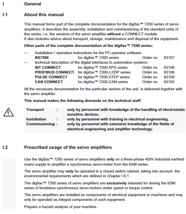
Core attribute: Digital servo amplifier, designed specifically for 6SM series brushless synchronous servo motors, only suitable for three-phase 400V industrial grounding power supply, providing speed/torque control, no built-in position control (needs to be extended through CONNECT module)
Model difference: Classified by output current, key parameters are shown in the following table:
|Model | Continuous output (S1 mode) | Peak output current | Power of ballast resistor | Applicable motor power|
|7201 | 0.9kVA | 3.0A | 75W | Low Power 6SM Series|
|7204 | 1.7kVA | 8.4A | 75W | Medium Power 6SM Series|
|7206 | 2.5kVA | 12A | 140W (requires BV forced cooling) | High power 6SM series|
Extended version: Supports BIT/CAN/PROFIBUS/PULSE CONNECT modules to achieve functions such as PLC, bus communication, pulse commands, etc; Optional - IL module achieves controllable torque limitation
Core hardware and environmental specifications | Specification categories | Key parameters|
|Power supply and output | Voltage: three-phase 400VAC (± 10%), frequency 47-60Hz; intermediate circuit voltage 560VDC, overvoltage threshold 750VDC|
|Control signal | Analog set value: ± 10V (14 bit resolution, input impedance 20k Ω); Digital I/O: 24V (PLC compatible)|
|Feedback Interface | Incremental Encoder (ROD): 500/512/1000/1024 pulses per revolution; SSI interface: maximum 1.5MHz clock|
|Physical dimensions | Standard model: 275 × 71 × 235mm; with BV cooling: 310 × 73 × 236mm|
|Environmental adaptability | Operating temperature: -25 ° C~+55 ° C (power reduction of 2.5% for every 1K increase above 45 ° C); Humidity 5% -85%, no condensation|
|Protection and insulation | Protection level IP20, compliant with VDE 0160 insulation standard, creepage distance meets EN 50178|
Installation and wiring specifications
Installation requirements
Installation location: It must be installed inside a closed switchgear to avoid conductive/corrosive environments, and installed vertically to ensure natural heat dissipation
Cooling distance: Adequate space should be reserved above and below the amplifier (refer to installation diagram V.7). If the ballast power of 7206 model is greater than 75W, BV forced cooling should be configured
Grounding requirements: The installation board needs to be grounded, and the amplifier is grounded in a single point star shape through a grounding bolt (M6). The cross-section of the grounding wire should be ≥ 10mm ²
Core wiring specifications
Cable separation: The distance between the power line (power supply, motor line) and the signal line (set value, feedback line) is ≥ 20cm, and they intersect at a 90 ° angle
Cable specifications:
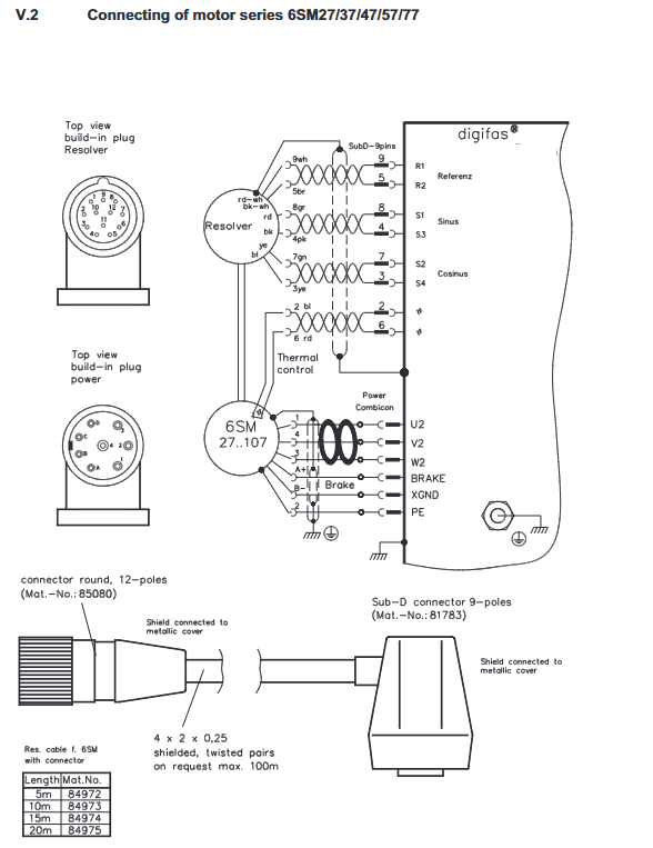
Motor wire: Use 1.5-2.5mm ² shielded wire for ≤ 25m; 25m with 4 × 1mm ² shielded wire and 3YL-06 choke box
Feedback line: Resolver/ROD/SSI wire with twisted pair shielded wire (0.25mm ²), up to 100m in length
Shielding treatment: All shielded cables must be grounded at both ends and connected with low impedance through shielding clips or metal joints
Key interfaces:
Power interface (L1/L2/L3): 3EFxx series filters need to be configured, and the user needs to provide a circuit breaker with phase loss monitoring
Auxiliary power supply: 25VDC (compatible with 18-36V), requires 1EF06 filter, maximum output current 2A (with brake)
Motor interface (U2/V2/W2): including brake wiring (BRAKE), brake voltage 24VDC ± 10%
EMC Compliance Configuration
Specific filters must be configured: 1EF06 for auxiliary power supply and 3EFxx series for main power supply
When the motor cable is greater than 25m, it is mandatory to use 3YL-06 choke box to suppress capacitive reactive current
All control signals must use shielded wires, and the shielding layer should be well grounded to the switchgear
Software configuration and debugging
BS7200 software functions
Operating environment: MS-DOS 3.3+, CPU above 80386, 1MB memory, VGA graphics card
Core functions: parameter configuration, real-time monitoring (current/speed/temperature), fault diagnosis, service mode (constant speed/constant current/reverse)
Connection method: Connect the PC parallel port or serial port (requires a power adapter) through a 9-core dedicated cable
Key parameter configuration
Motor parameters: number of motor poles (2-12 poles), number of resolver poles (2/4/6), to be matched with 6SM motor
Current control: Irms (continuous current, maximum motor rated current), Ipeak (peak current, maximum 4 × Irms), Kp (proportional gain 0.1-8), Tn (integration time 0.1-10ms)
Speed control: Kp (proportional gain 1-61), Tn (integration time 0.1-9999ms), SW ramp (set value ramp 2-8000ms), speed limit (800-6000rpm)
Interface parameters: ROD/SSI selection, resolution setting, NI offset (zero pulse position)
debugging process
Power off inspection: wiring correctness, grounding continuity, motor and amplifier parameter matching
Power on preparation: First, turn on the 25VDC auxiliary power supply, and the green LED will light up (initialization takes about 0.5 seconds)
Software connection: Start BS7200, read and verify parameters (motor pole number, current limit, speed limit)
Enable test: Set the value to 0V, enable the amplifier (X3/16 terminal 24V), and the motor is in the braking state
Run test: Input 0.5V simulated set value (or start service mode), observe motor operation status, optimize gain parameters
Multi axis debugging: Multi axis systems require separate debugging of each amplifier, and when sharing intermediate circuits, unified ballast parameters are required
System functions and protection
Core control function
Double loop control: current loop (update rate 8.33kHz), speed loop (including PID regulation), supporting phase compensation (0-45 ° electrical angle)
Set value processing: Supports ± 10V differential input, built-in offset compensation, slope adjustment (2-8000ms)
Energy feedback: The braking energy is converted into heat through the ballast resistor, and multiple axes can be connected in parallel to share the ballast capacity with the intermediate circuit
Monitoring output: Analog output (X3/23) can choose between current (IDC, 8-bit resolution) or speed (VTA, 10 bit resolution) monitoring
protection function
Fault types: including undervoltage (65VDC threshold), overvoltage (750VDC threshold), overcurrent, output stage fault, overheating (heat sink 80 ° C/internal 70 ° C), motor overheating (145 ° C), braking fault, resolver fault, grounding fault, etc
Fault response: All faults trigger the red LED to light up, BTB relay to disconnect, output stage to shut down, requiring reset enable or power-off restart
Other protections: I ² t current monitoring (to prevent overload), limit switch protection (PSTOP/NSTOP, can set stop/disable direction)
Troubleshooting and Maintenance
Common fault handling | Fault signal | Possible causes | Troubleshooting measures|
|Overvoltage | Excessive braking energy, insufficient ballast power | Increase ballast power parameters, shorten braking ramp, parallel intermediate circuit|
|Output level fault | Motor line short circuit/grounding, output level overheating | Check motor cable, improve heat dissipation, return to factory for repair|
|Resolver malfunction | Loose wiring, cable breakage, model mismatch | Check the Resolver cable and confirm 2/4/6 pole pairs match|
|Motor not turning | not enabled, set value circuit broken, motor phase missing | Check ENABLE signal, set value cable, motor phase wiring|
|Motor oscillation | High speed loop gain, poor shielding | Reduce Kp parameter, replace shielding cable, ensure AGND grounding|
Maintenance and Storage
Daily maintenance: Maintenance free design, the outer shell can be wiped clean with isopropanol if it is dirty, and immersion or spraying of cleaning agents is prohibited
Storage requirements: temperature -25~+55 ° C, humidity ≤ 95%, no condensation, stacking height ≤ 10 boxes; Storage for over 1 year requires capacitor reconfiguration (single-phase 230VAC power supply for 30 minutes)
- YOKOGAWA
- Reliance
- ADVANCED
- SEW
- ProSoft
- WATLOW
- Kongsberg
- FANUC
- VSD
- DCS
- PLC
- man-machine
- Covid-19
- Energy and Gender
- Energy Access
- Renewable Integration
- Energy Subsidies
- Energy and Water
- Net zero emission
- Energy Security
- Critical Minerals
- A-B
- petroleum
- Mine scale
- Sewage treatment
- cement
- architecture
- Industrial information
- New energy
- Automobile market
- electricity
- Construction site
- HIMA
- ABB
- Rockwell
- Schneider Modicon
- Siemens
- xYCOM
- Yaskawa
- Woodward
- BOSCH Rexroth
- MOOG
- General Electric
- American NI
- Rolls-Royce
- CTI
- Honeywell
- EMERSON
- MAN
- GE
- TRICONEX
- Control Wave
- ALSTOM
- AMAT
- STUDER
- KONGSBERG
- MOTOROLA
- DANAHER MOTION
- Bentley
- Galil
- EATON
- MOLEX
- Triconex
- DEIF
- B&W
- ZYGO
- Aerotech
- DANFOSS
- KOLLMORGEN
- Beijer
- Endress+Hauser
- schneider
- Foxboro
- KB
- REXROTH
- YAMAHA
- Johnson
- Westinghouse
- WAGO
- TOSHIBA
- TEKTRONIX
- BENDER
- BMCM
- SMC
- HITACHI
- HIRSCHMANN
- XP POWER
- Baldor
- Meggitt
- SHINKAWA
- Other Brands
- UniOP
- KUKA
- IBA
- Beckhoff
-
Woodward 8272-796 - Real Power Sensor Module 115/230v-ac
-
Woodward 5463-873 - NetCon Output Module
-
Woodward 8271-567 - Load Sensor Module 120/208v-ac
-
Woodward Type UG-8 P/N 8522-300 EG - Governor R.P.M 1075-1650 With Motor Groschopp
-
WOODWARD 9905-971 REV J - LINKNET 16 CHANNEL DISCRETE INPUT MODULE
-
WOODWARD 8280-3014 - 723 PLUS DIGITAL CONTROL REV NEW
-
Woodward 505DE - Digital Control System
-
Woodward 5453-750 - Ethernet Interface FTM
-
Woodward 9907-018 Rev H - 2301A Load Sharing & Speed Control
-
WOODWARD 5420-1080 V4.3 - BOARD-PPA WITHBOX
-
Woodward b 8271-347SP - 2301 speed control
-
Woodward 9905-795 Rev B - Digital Synchronizer and Load Control
-
Woodward 9905-377 Rev. A - 2301A Load Sharing and Speed Control
-
WOODWARD 8272-582 - Generator speed control module
-
WOODWARD 9907-247 REV K - 828 DIGITAL CONTROL UNIT
-
WOODWARD 5466-353 REV C - NETCON MAIN CHASSIS TRANSCEIVER
-
Woodward Type UG-8 P/N 8524-708 - Governor 760-1560 Governor R.P.M
-
WOODWARD 9907-247 REV K - 828 DIGITAL CONTROL UNIT
-
WOODWARD 8440-1831 REV. H - EASYGEN3000 3200-5 - WITHOUT ACCESSORIES
-
WOODWARD 8444-1002 REV G - UMT1 MEASURING TRANSDUCERS
-
Woodward 5410-312C - Digital Marine Control Printed Circuit Board
-
Woodward 9905-799 REV F - Digital Synchronizer & Load Control , V#456
-
Woodward 9907-014 - 2301A for controller
-
Woodward Type UG-8 P/N B522-446 - Governor R.P.M 500-1200
-
WOODWARD 8272-221 REV.B - DIGITAL REFERENCE UNIT
-
Woodward 8901-037 - Booster Servomotor Single
-
WOODWARD 8444-1019 REV G - UMT 1 MEASURING TRANSDUCER
-
WOODWARD 1767-367 Z21 WK 0920702 - GOVERNOR MOTOR 2700 RPM KM 58-20 K 230V
-
WOODWARD 9905-972 Rev:G - LINKNET 6 CHANNEL 4-20mA OutPut
-
Woodward E8250-501 - Actuator Governor
-
WOODWARD 5466-258 REV M - SIMPLEX DISCRETE I/O MODULE
-
WOODWARD 5501-470 REV E - NETCON CPU MODULE
-
Woodward 8406-120 rev H - egcp-2 digital control
-
Woodward 8440-1799 - Easygen-350 Rev B
-
Woodward 8440-1878 - DSLC-2 Digital Synchronizer Load Control
-
Woodward 5464-843 - Cpu Processor Module
-
WOODWARD 8440-1409 Rev. J - MFR2 MDE Synchronization & Protection MSP
-
Woodward 9907-014 - controller
-
WOODWARD 9907-173 - LOAD SHARING MODULE 120V
-
WOODWARD 8440-1831 REV. K - EASYGEN 3200-5 - WITHOUT ACCESSORIES
-
Woodward 9905-969 - LinkNet Module LinkNet 6C 4-20ma in w/24v
-
Woodward 8520-498 - Governor Type UG-8 Governor R.P.M 850-1650
-
WOODWARD 5466-257 REV.-C - NETCON 5000 MODEL REMOTE TRANSCEIVER I/O MODULE
-
WOODWARD 8800 - 1001 REV-C - DSS-2, 2 CHANNEL DIGITAL SPEED SWITCH
-
WOODWARD 5501-467 REV. C - MICRONET SIMPLEX POWER SUPPLY
-
Woodward 8273-584 - Atlas-ii Digital Control
-
Woodward 8440-1019 b - spm-d10 synchronizing system
-
Woodward CSC3SUWA REV K - CSC3SUWA Controller
-
Woodward 5441-693 Rev B - Digital I/O Module
-
WOODWARD DPG-2201-002 REV.D - Governor Onan DIGITAL SPEED CONTROLLER
-
Woodward 9905-377 Rev. A - 2301A Load Sharing and Speed Control
-
WOODWARD 8440-1884K - GENERATOR CONTROLLER EASYGEN-2500-5 REV,K
-
WOODWARD 8404-1006 - Industrial Component
-
WOODWARD 5437-1118 - PROTECHTPS MODULE Relay Bulkhead Panel
-
Woodward 8440 1801 Rev C - Easygen-350-50B/X Genset Control Engine Generator 24VDC
-
WOODWARD 5466-348 - MODULE
-
Woodward 9905-799 REV F - Digital Synchronizer & Load Control , V#456
-
Woodward 9907-018 - 2301A Load Sharing & Speed Control Rev H
-
Woodward GM9412H918-R2 1766-039 REV E - Cruise Control Motor
-
5466-258 WoodWard - 48 Input 24 Output Discrete I/O, (UPP)
-
WOODWARD 5484-877 - PM MOTOR 24VDC 15RPM
-
Woodward 8272-221 B - Digital Reference Unit
-
Woodward 9905-796 - Digital Synchronizer And Load Control (Rev. H)
-
WOODWARD 5441-645 REV.G - 10AMP RELAY INTERFACE 11459968
-
Woodward 9907-207 - 721 Digital Control 88-132VAC
-
WOODWARD 8272-582 - APM MOTOR CONTROL AC/DC 100~220V
-
Woodward 5464-843 - Cpu Processor Module
-
Woodward 9905-001 L - SPM-A Synchronizer 115/230V 50/60Hz 10W
-
Seg Power Protection PCK4 P/N 8445 1006 A / PCKR-MW - Protection Relay 24VDC
-
Woodward 8405-062 - Actuator
-
Woodward 5464-738 - Industrial Control System
-
Woodward CSC3HUWB - controller
-
Woodward 8272-517 - PM Motor Control 220vac
-
Woodward 8272-582 - APM Motor Control
-
Woodward LR20025 MFR1375M MFR 1 - Controlling
-
Woodward 9905-392 - Proact Driver Model III
-
WOODWARD 8250-774 - ACTUATOR/GOVERNOR
-
Woodward 505DE - Digital Control System
-
Woodward 8280-303 D - 721 Digital Control Rev.G 2.0 AMP 28 VDC
-
WOODWARD DPG-2201-002 REV NEW - DIGITAL CONTROLLER
-
WOODWARD 8272-286 - 2301A LOAD SHARING & SPEED CONTROL MODULE
-
WOODWARD 8440-1884 REV M - GENSET CONTROLLER EASYGEN-2500-5/P1
-
Woodward 9905-797 Rev. M - Digital Sync And Charge Control
-
W0ODWARD ART-01681 - IDS Communicator Control Box
-
Woodward 8273-584 - Digital Control Unit ATLAS-II REV: A 18-32VDC, 60W
-
WOODWARD 5501-470 REV E - NETCON CPU MODULE
-
Woodward 1752 1752-227 - Revision D FireFly Current Load input Engine Control
-
Woodward 8440-1877 - MSLC-2-5 Control
-
Woodward 8271468 - Generator Loading Control (Rev. D)
-
Woodward 9905-387 - Pro Act Driver Model lll (Rev. F)
-
Woodward 9905-363 - Sincronizzatore Digitale E Controllo Carico
-
WOODWARD 8272-583 - APM MOTOR CONTROL
-
WOODWARD EGCP-2 - Digital Generator Control Panel 4-20MA 5V 500HZ
-
Woodward 9905-392 - Proact Driver Model III
-
Woodward 9905-392 - Proact Driver Model III
-
Woodward 8270-007 - Load Signal Control
-
Woodward 8271-651 - Digital Speed Reference
-
WOODWARD 8440-2219 - EASYGEN-2500-5-P1-K49 GENSET CONTROLLER
-
Woodward D8271-394 - 2301 Load Sharing And Speed Control Module 20-40v-dc
-
Woodward 8200-1504 Rev:E - Peak200 Steam Turbine Control Front Panel Mount HVAC
-
WOODWARD 8444-1022 REV F - UMT 1 MEASURING TRANSDUCER
-
WOODWARD 8440-1923 A - EASYGEN-3200-5 CONTROLLER
-
WOODWARD 9907-014 - 2301A controller
-
Woodward 8272-583 - Amp Motor Control DC24V
-
Woodward 9907-147 REV N - ProTech 203 Overspeed Protection System
-
Woodward 8270-417 - 2301 speed sensor
-
Woodward 8272-583 - Amp Motor Control DC24V
-
Woodward 8934-658 - Repair Kit UG8D Governor
-
Woodward 5437-281 - analog module
-
Woodward 8440-2177 A - SPM-D2-10 Digital Synchronising Controller
-
SA-4478 EPS1000 - Speed Switch
-
Woodward 9907-014 Rev: J - 2301A Speed Control
-
Woodward 9907-026 Rev C - Load Sharing Module
-
Woodward B8271-464 H B8271464 - 2301 Speed Control
-
WOODWARD 8440-1667 REV C - SPM-D10 SYNCRONIZING UNIT
-
Woodward 8440-2082 - EASYGEN-3200XT-P1 Engine Generator Control
-
Woodward 8406-120 rev H - egcp-2 digital control
-
WOODWARD SPM-D - SYNCHRONIZING SYSTEM
-
Woodward 8271-651 - Digital Speed Reference
-
WOODWARD 8444-1074 A - MODULE
-
WOODWARD 8440-2050 Rev B - EASYGEN-3200-5 CONTROLLER
-
Woodward 8440-1613 REV E - GCP30 Genset Control Package
-
Woodward 9907-018 - Load Sharing & Speed Controller Rev H 90-240VAC
-
Woodward 5466-315 - module
-
Woodward 9905-204 Rev N - SPM-A synchronizer
-
Woodward XG2 - Protection relay
-
WOODWARD 9907-175 LOAD SHARING MODULE REV A - Load Sharing Module
-
Woodward 9907-166 REV: N - 505E Turbine Control 110V AC/DC

K-JIANG

Add: Jimei North Road, Jimei District, Xiamen, Fujian, China
Tell:+86-15305925923